This paper was first presented at GPD 2023.
Link to the full GPD 2023 conference book: https://www.gpd.fi/GPD2023_proceedings_book/

Authors:
- Austin Bensend, Enclos
- Marco Zaccaria, AGC
Introduction
With the advent of heat-treated glass, stiffness rather than strength often governs the design of architectural flat glass. Traditionally, fixed glazing supported by a perimeter frame utilizes the following strategies to improve stiffness when otherwise deemed inadequate for the applied loads: increased thickness, reduced span, or both. Now, a novel approach to generate a flat plate with enhanced stiffness has been identified. This approach is scalable, offering the potential for improved stiffness for both large-format glass and thin, chemically tempered glass such as AGC’s Falcon Glass. It is this latter application that formed the inspiration for the study presented here, a collaboration between AGC and Enclos, demonstrating Enclos’ novel pre-stressed plate structure technology.
Background
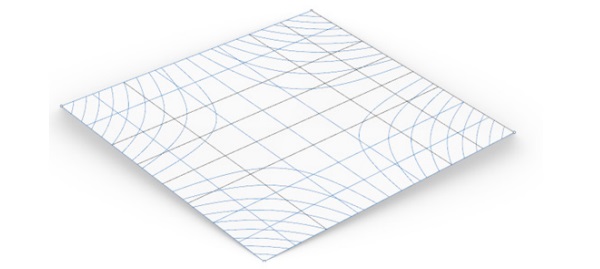
The concept of using pre-stress to stiffen glass has its inspiration in recent studies at Enclos into cold-warped glass behavior. Coldwarped glass is commonly generated by elastic deformation of flat glass in uniform torsion by means of its perimeter framing. This operation transforms the flat glass into a hyperbolic paraboloid shape (Figure 1) when it is twisted out of plane (Timoshenko and WoinowskyKrieger, Eekhout et al, Galuppi et al). In this deformed state, it was observed that the glass exhibits a loss of stiffness for a given applied face load (Bensend, 2018).
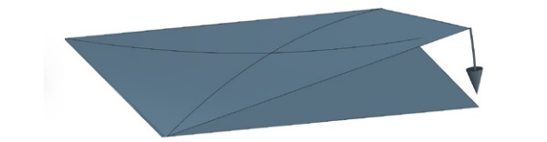
Since cold-warping planar glass into a hyperbolic paraboloid results in loss of transverse stiffness, curiosity led to ask what would happen if a shape that was initially a hyperbolic paraboloid was cold-warped by forcing perimeter supports to a planar shape (Figure 2). The hypothesis was that the entire sheet would become planar, and transverse stiffness would increase.
Exploratory finite element models aligned with this hypothesis; a formed hyperbolic paraboloid elastically held flat at its perimeter resulted in a planar, pre-stressed element. As predicted, these models indicated that the resulting glass exhibited improved stiffness compared to conventional flat glass. The presence of membrane stresses resulting from the elastic deformation was identified within these models. This consists of a net membrane tension region near the mid-span of the glass, which is balanced by regions of compression stresses near the edge of the glass (Bensend, 2021).
Unlike the earlier cold-warping study by Bensend in 2018, where compressive stresses were the culprit for a loss of stiffness, the glass in these models exhibits a tension region that increased stiffness, specifically when in the range of large deflection behavior.
For conventional architectural flat glass, large deflection behavior is common; deflections are often many multiples of the thickness of each lite, which is well into the realm of large deflection behavior (Hakim and Abramovich). Large deflection behavior occurs when the mid-depth of a plate is strained during application of transverse load (Timoshenko and Woinowsky-Krieger). The resulting membrane stresses increase the plate stiffness as load increases. In other words, uniform incremental increases in load result in decreasing incremental increases in deflection.
For the pre-stress approach, the initial pattern of net tension membrane pre-stress essentially emulates the membrane forces that develop within a plate loaded to a large deflection. However, because these stresses are generated as the glass is deformed into a planar element, they exist without the corresponding transverse deflection that otherwise would accompany them. The result is a measurable reduction to the transverse deflection when face loads are applied, compared to a conventional plate of the same thickness.
Analysis
Analysis and testing were commenced to create and validate comparison plots of load versus deflection for both conventional and pre-stressed glass specimens. The primary objective was to demonstrate that the prestressing approach served to stiffen the glass as predicted numerically. Finite element analysis of the specimens was required at the outset to identify the appropriate degree of curvature in the initial formed shape and confirm appropriate load steps. Conventional and pre-stressed glass alike were to be tested as monolithic panes held in a frame, and with net deflection measured at each load step.
For the study presented here, glass dimensions of 800mm x 800mm were considered. This size selection was primarily for ease of handling, chemical tempering, and testing, while still allowing for the necessary large deflection behavior in two-way bending. Based on recommendations from the vendor executing the hot-forming, minimum glass thickness of 5mm was selected for the study. Preliminary study indicated that total warpage of roughly 100mm out of plane seemed appropriate for these dimensions.
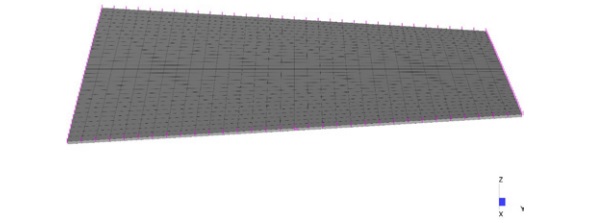
Rhinoceros 6 geometry models were generated with Grasshopper scripts to create the required surface. The surface geometry was then imported into Strand7 R3.1.1 finite element software and meshed into a gridwork of 32 x 32 Quad4 plate elements, sized 25mm x 25mm each (Figure 3), with thickness of 4.8mm based on the minimum thickness tolerance. The origin of the model was located at the center of the warped plate model, and the X-Y plane interesected the plate at the origin. Two lines coincident with the X and Y axes at Z = 0mm, running through the origin also lie on the warped surface. At the four corners, alternating values of Z = +25mm and Z = -25mm occur for the initial undeformed state. Care was taken to not overconstrain the supports.
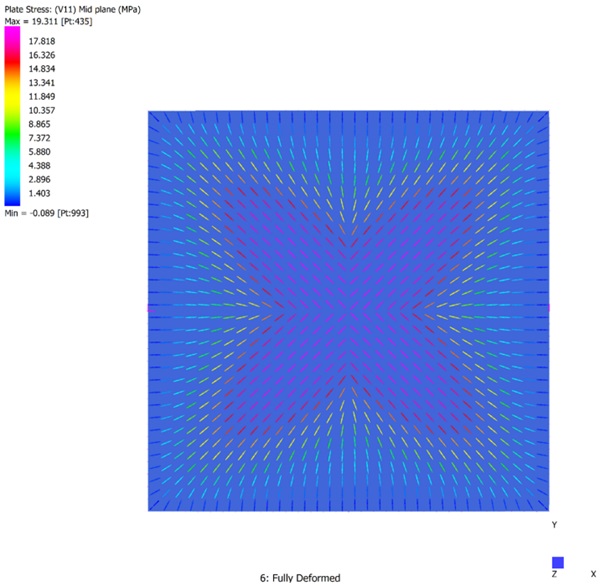
Pre-stressing was introduced into the model by imposing Z direction displacement at the perimeter nodes in the opposite value of the initial Z coordinate in a series of five deformation load steps. After perimeter nodes were enforced to Z=0mm, the entire surface became planar in the model. A pattern of pre-stress resulted, shown by the principal 11 tensile stress at mid depth of each plate element in Figure 4.
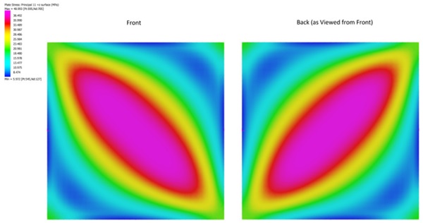
Surface stresses that resulted were higher, up to 41MPa, as seen in Figure 5. These stresses are below the anticipated residual compressive surface stresses available from either chemical or thermal tempering, indicating capacity remains to resist further imposed loads. Surface stresses are maximum in diagonal regions; on the front face, the diagonal pattern appears from upper left to lower right, and on the back face from upper right to lower left. The orientation of stress pattern varies depending on which face the results are presented.
Following the deformation steps, loading was applied to the stressed model up to 2kPa in increments of 0.2kPa. At 2kPa face pressure, surface stresses increased marginally on the face opposite the load to a value of 44.7MPa, but principal tension stresses remained below the residual compressive surface stresses.
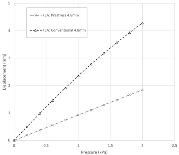
The same load steps, supports, and element sizes (excluding pre-stressing deformations) were conducted for a conventional, flat 800mm x 800mm x 4.8mm glass specimen. A plot of deformation versus applied pressure was constructed for both cases to show center of glass deflection relative to the Z=0 plane (Figure 6). What becomes apparent is that while both specimens deflect from the applied pressure, the pre-stressed version exhibits much less deflection and less nonlinearity.
In the case presented here, the pre-stressed glass at the 2kPa load step deflects less than half the magnitude of that for the conventional glass at the same load. This represents an opportunity for meaningful lightweighting or performance improvement as it relates to the deflection during a pressure loading event.
Testing
Validation testing and modeling was conducted next. A set of 800mm x 800mm specimens were procured, hot-formed and warped 100mm out of plane. These warped specimens were then chemically tempered to provide adequate strength for the pre-stressing operation. An additional set of 800mm x 800mm flat annealed specimens were also procured as the reference specimens. Both the flat and curved specimens measured 4.85mm actual thickness.
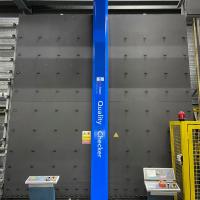
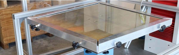
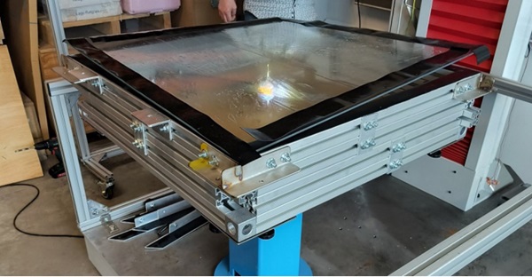
As an initial step prior to testing, a piece of pre-stressed glass was placed and captured flat in a frame to assess visual quality. It appeared to take on a planar shape with surface flatness closely matching what was anticipated, as seen in Figure 7.
The next step was to install one specimen in a frame more suitable for testing. 45mm Bosch profiles were adapted to create a framework to support and hold the warped specimens. These profiles were fixed to a flat piece of 20mm plywood supported only at the center. To net out the stiffness of the plywood, a deflection gage was supported from a profile spanning between frame sections that the underside of the glass. It took multiple stacked profiles to gain enough clearance for the deflection gage to be situated beneath the point load. A protective film was placed on the glass prior to testing. The stacked profiles, protective film, and the deflection gage are visible in Figure 8, as is the shape of the unstressed glass prior to the application of the pre-stressing deformation.
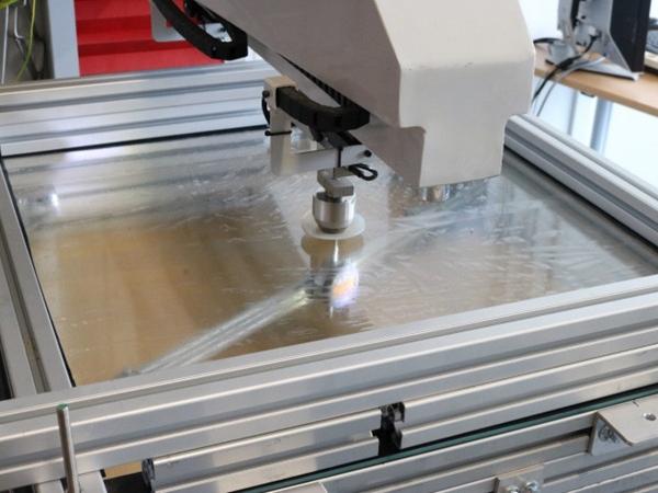
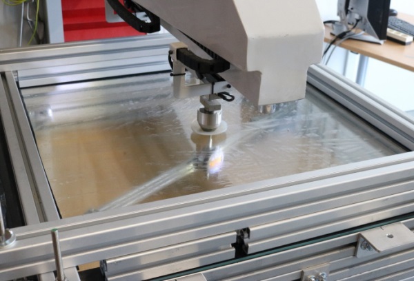
The specimen was then clamped flat into a planar frame and tested with a concentrated load on a universal testing machine with a 10000 N load cell by Easydur at AGC’s Technovation Center, as seen in Figure 9. Finite element modeling was conducted to the matching thickness, gravity loads, support and deformation steps as the testing. Following the pre-stressed specimen, the same testing and modeling steps (other than pre-stressing) were then completed for the annealed, flat specimen.
A comparison plot for the finite element results and test specimen results showing the load versus deflection curves is provided in Figure 10. It is clear from this figure that the predicted improvement to stiffness from the finite element modeling appears in good agreement with the test results for both the conventional and pre-stressed glass specimens.
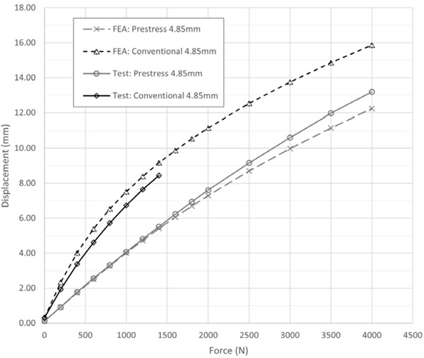
Note that the last data point for the conventional case was the 1400N concentrated load step, after which it broke due to its limited annealed capacity. It’s also worth noting that EPDM material was placed between the glass and the frame, which may be a source of added displacement relative to the finite element results at the higher load steps. Stresses were not analyzed for this test case due to the challenging nature of predicting stresses at the point of load. Regardless, the capability of the technology to enhance stiffness is clearly seen.
Conclusion
Following these promising results, the opportunity to reduce glass deflection using such a membrane pre-stressing approach is shown to be valid. Furthermore, the initial starting shape of hyperbolic paraboloid demonstrates benefit in that the pre-stressing can be applied in a predictable and controlled manner. Much work remains to fully realize the extents and limitations of this approach. Regardless, it is exciting to consider how glass may be enhanced by this pre-stressing technology to further elevate the performance of glass in architecture and beyond.
References
Bensend, A. 2018. ‘The Effects of Cold Warping on Glass Stiffness’. Challenging Glass 6 Conference on Architectural and Structural Applications of Glass. Belis, Bos, Louter, Veer, and Nijsse (eds.), May 2018: pp. 85-96. Delft University of Technology, Netherlands. https://doi.org/10.7480/cgc.6.2119
Bensend, A. 2021. ‘Pre-stressed Plate or Shell Structures’. U.S. Patent 10,913,243.
Eekhout, M., Staaks, D., and Van Herwijnen, F. 2004. ‘Cold Bent Glass Sheets in Façade Structures’. Structural Engineering International (SEI), 14(2): pp. 98-101.
Hakim G., Abramovich H. 2022. ‘Large Deflections of Thin-Walled Plates under Transverse Loading— Investigation of the Generated In-Plane Stresses’. Materials, 15(4): 1577. https://doi.org/10.3390/ ma15041577
Galuppi, L., Massimiani, S., Royer-Carfagni, G. 2014. ‘Buckling Phenomena in Double Curved Coldbent Glass’. International Journal of Non-Linear Mechanics. 64: pp. 70-84. https://doi.org/10.1016/j. ijnonlinmec.2014.03.015
Timoshenko, S., Woinowsky-Krieger, S. 1987. ‘Theory of Plates and Shells’, 2nd ed. New York, NY, McGrawHill: pp. 43-44, 47-48, 396.