
This paper was first presented at GPD 2023.
Link to the full GPD 2023 conference book: https://www.gpd.fi/GPD2023_proceedings_book/

Authors:
- Valérie Hayez - Dow Silicones Belgium
- Simona Bianchi - Delft University of Technology, Delft, Netherlands
- Guido Lori - Permasteelisa S.p.A., Vittorio Veneto, Italy
- Jie Feng - Dow Silicones Corporation, USA
- Jon Kimberlain - Dow Silicones Corporation, USA
Some of the world’s largest metropolitan areas are located within highly active seismic regions. Earthquakes can lead to major architectural and human impact, especially when glazed curtain walls are involved. Silicone structurally glazed façades are a durable assembly system, known to optimize the envelope’s weatherproofing performance and aesthetics, which can also potentially contribute to a better seismic resistance of the building’s façade. This paper presents the initial results of a seismic study of silicone bonded glass curtain wall systems, combining both finite element analysis and experimental validation.
Applying finite element analysis to silicone requires appropriate material models which suitably mimic the typical loading undergone during specific events. Material models were validated using test results of the experimental campaign carried out at the laboratory of Permasteelisa Group on full-scale unitized curtain walls. These tests evaluated variation of joint dimensions (width and thickness or aspect ratio), pane dimensions, frame flexibility and influence of loading mode. The focus of the study was on the damage mechanisms of the curtain walls.
1. Introduction
Unitized curtain walls are widely used in modern architecture, due to their benefits in terms of lightness, quality control, ease of construction and quick installation. However, recent earthquake surveys have shown slightto-extensive damages to these non-structural elements [Baird et al. 2011, Bârnaure 2013]. There is a limited amount of studies about the seismic performance of the overall façade system when compared to the information available about main structural elements and other façade typologies such as infill walls. This is due to the need of expensive and timeconsuming tests to simulate seismic loads acting over this type of elements [Huang 2017]. Moreover, the information available does not provide clear indications about curtain wall (CW) modelling, including its connections.
Therefore, there is a need to increase substantial research regarding the seismic performance of CW by analyzing samples experimentally and by creating a finite element model to replicate the behavior of a tested sample [Lalas 2022], validate the model and allow further parametric analysis.
In the realm of structural silicone glazed (SSG) systems, recent research [Kimberlain 2022] successfully used a Mooney Rivlin hyperelastic material model of DOWSIL™ 983 Structural Glazing Sealant in seismic modeling. This study explored the structural sealant joint performance modeling for seismic drift test through finite element analysis (FEA) simulation. By calibrating the maximum principal strain limit for the sealant material from tension-adhesion (TA) joint test, it was found that the selected sealant material can reach a peak strain of 118% at failure. This calibrated strain limit was used to assess the performance of the structural sealant joint in a previously performed seismic test. The simulation and testing of a full window system consisting of multiple insulating glass units (IGU) showed that the maximum principal strain in the sealant joint varies according to the location and the dimension of the bonded glass unit.
This confirms the importance to evaluate the SSG joint seismic performance and demand (drift level) based on the actual window system layout and bonding configuration. Moreover, from the modeling of the TA test pieces and seismic drift test, it appeared that a similar peak strain limit can be used as design criteria in the seismic test simulation to predict if the sealant joint will develop tear failure under a given drift level. As the predicted peak strain in the sealant joint reaches a peak value, due to the distortion of the sealant joint, an out of plane direction tension stress will occur, contributing eventually to the glass fall out. With good match between FEA simulation and full-scale seismic test, this study confirmed that simulation based calculation can be an effective approach to predict sealant performance in seismic performance testing even if the sealant joint has a non-traditional design, and this can enable a more effective assessment of window system seismic performance before performing the validation test.
To further support these learnings in the field of seismic performance of SSG systems, Dow participates to an EU-funded research project, SAFE-FACE, led by Delft University of Technology and Permasteelisa Group. This project aims at investigating the seismic behaviour of full-scale unitized curtain walls from a holistic and multi-performance perspective [Bianchi 2022], looking at serviceability performance and ultimate limit state of alternative facade designs through an extensive research program. The tests involve various facade configurations consisting of dry (gasket) vs. wet (SSG) glazing systems with different construction details. In the first experimental phase, specimens were tested according to the Japanese regulation (quasi-static cyclic testing) [Bianchi 2022, Nuñez Enriquez 2022].
These experimental test results allowed improving the modelling strategies through the calibration and validation of numerical models [Nuñez Enriquez 2022] using Diana Software [Diana 2023]. The approach of this research is focused on the individual evaluation of specific connections in the façade, the transom, mullion, top and bottom brackets, as well as the silicone, for their further implementation in a model simulating a full-size CW subjected to seismic displacements. Similar to Dow’s approach for DOWSIL™ 983 Structural Glazing Sealant in seismic testing, the silicone behaviour was captured successfully using a hyper-elastic Mooney-Rivlin material model for DOWSIL™ 993 Structural Glazing Sealant.
The next phase of this research program evaluates a global CW façade through quasistatic (monotonic) and dynamic testing (sinusoidal, real earthquake signals). The ultimate resistance and the different mode of failures of the façade are investigated in detail as there is little information available on this aspect. Indeed, the intent of a seismic testing protocol required for a specific building project, is mainly to prove that the facades comply with the project requirements and failure is typically omitted. This paper documents specifically the preliminary results of the silicone study, looking at the influence on the silicone behaviour of the frame movement accommodation capability, the silicone aspect ratios or the type of loading. Finally, the sequence of damage mechanisms under increasing levels of shaking is identified. The collected experimental data will be used in a next phase to validate the model and failure mechanism, and perform subsequently a parametric study to derive dimensioning guidelines.
2. Initial FEA and Experimental testing
2.1. Samples description
Several façade units are available for the full CW seismic testing as illustrated in Fig. 1a. The specimens mainly differ in the height, whereas the width is identical. Two units of each type are available for testing. A detail of the joint and frame used for the experimental testing is provided in Fig. 1b.
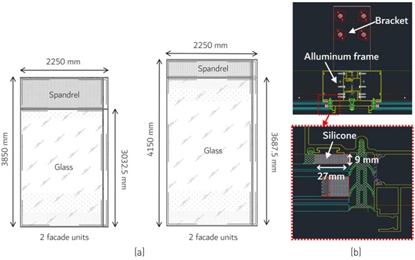
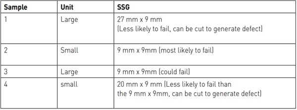
The original joint dimensions for the tested units was 27mm x 9mm. It was possible to reglaze the units to achieve variation in joint design and increase the probability of failure during the seismic testing. The bite could be decreased while the thickness could only be increased. Four joint dimensions were identified for evaluation: 9mm x 9mm, 20mm x 9mm, 27mm x 9mm (original dimension). FEA was used to model the samples before the seismic test was performed, to determine which units would be most susceptible to fail, as a function of seismic test type, joint and panel dimension, and frame movement capability (rigid versus flexible). The FEA results drove the specimen installation and test sequence. Furthermore the use of the failure criterion based on peak strain allowed to get an estimate of the location with the highest probability of failure and to ensure accurate measurements would be planned in those area through strain gauges, accelerometers and video cameras. The collected experimental data will allow the final validation of the model.
2.2. FEA analysis
The numerical simulations were performed using a commercial FEA software ABAQUS. The silicone structural sealant was assumed to be incompressible and fully integrated Hybrid hexahedral elements (C3D8H) were used to prevent element locking, i.e. exhibiting an unphysically stiff response to deformation.
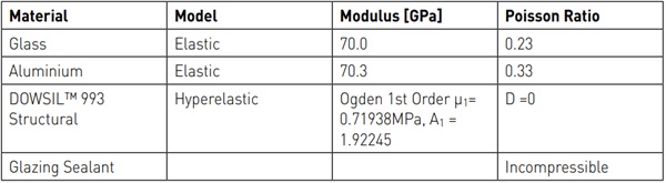
When relevant, glass, aluminum and structural sealant were modeled in the simulation based on their typical material behaviour, as summarized in Table 1. The hyperelastic material model of DOWSIL™ 993 Structural Glazing Sealant was fully characterized through uniaxial tension, biaxial tension and planar tension testing [Sitte 2021]
The approach used in Kimberlain (2022) for DOWSIL™ 983 Structural Glazing Sealant was applied in this seismic study with DOWSIL™ 993 Structural Glazing Sealant. Sitte (2021) validated the hyperelastic material model using experimental results of a small scale TA joint and identified the maximum principal strain as a good indicator of material failure in tension mode. This 102% peak could be used as a design criterion for sealant joints in computer assisted engineering based design iteration.
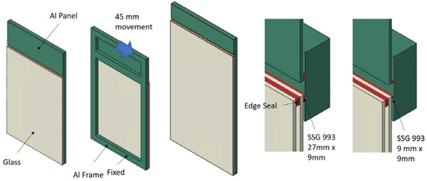
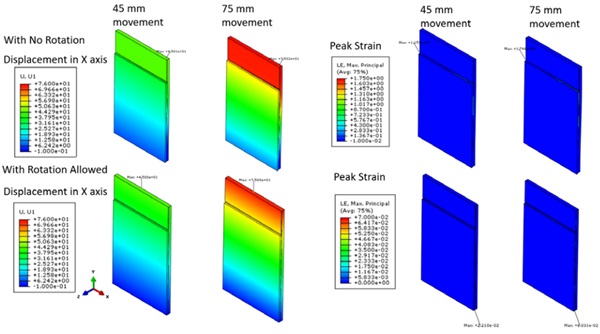
For the modeling of the curtain wall (Figure 2), a number of simplifications were performed. In a first step a fully rigid solid frame was used, as illustration of a worst case scenario as all deformations due to the seismic event are imposed on the joint. Next, the solid frame was allowed a rotation capability to reproduce a CW with improved frame design for seismic events. The edge of the insulating glass unit was only modeled using silicone and without spacer. The presence of air in the cavity was neglected. The top panel (spandrel) was modeled as aluminum plate. Not knowing about exact clearance between spandrel and glass, 45mm was used. The potential influence on the silicone behaviour of the strain rate of the tests (dynamic versus monotonic quasi static) was not considered. The movement imposed reached 45mm and 75mm.
As an illustration, Figure 3 shows the displacements and peak principal strain in the 9x9mm² joint, reached for the fully rigid and the flexible frame at 45mm and 75mm movement. When the frame is prevented from accommodating the seismic movement, the resulting strain levels in the silicone reach relatively high values, up to 175% at 75mm deformation. On the other hand, as soon as the frame is given some flexibility, the peak strain in the silicone is significantly reduced, as low as 7% for the highest deformation.
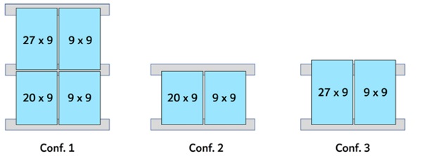
Repeating the FEA for the different joint dimensions, the failure risk appeared to be highest for the above illustrated smallest joint dimension (9x9mm²). The spandrel area is a smaller pane for which no risk of failure was identified. For the vision area, panes having a smaller height (3m) are more rigid than the larger panes (3.6m height) and therefore show and increased risk of failure. When increasing the deformation from 45mm to 75mm, the 27x9mm² joint slightly increases in strain but probably not enough to generate failure. Based on these preliminary and simplified FEA models, it was decided to bond both one small (3m) and one large (3.6m) unit with a 9x9mm² joint, as both are likely to fail and it will give us some insight in the influence of glass aspect ratio.
It was also decided to keep one small unit in 20x9mm²: this unit would be less likely to fail than 9x9mm², but more likely than 27x9mm² and having it in small format puts more probability of failure. The last large unit should be 27x9mm². This joint is in any case unlikely to fail, so it represents the other extreme of the “small unit with 9x9mm²”. Table 2 and Fig. 4 present an overview of the design choices and specimen configurations utilized in the study. The evaluation of the silicone damage specifically involved the configurations with two units (configuration 2 and configuration 3 in Figure 4).
The choice of joint dimensions should give the possibility of evidencing a potential influence of the joint aspect ratio as it is known that lower aspect ratios increase the movement capability [Descamps 2017, Descamps 2018] which is needed to accommodate extreme deformations occurring during seismic events. Moreover, the variation of the joint aspect ratio enables to assess the utilization factor and hierarchy of damage of the different components in the façade system (glass, frame, silicone). In case testing would not generate failure for any of the units, it was considered to induce a cut simulating a crack in the silicone due to the seismic event.
The goal being to understand if a CW showing damaged silicone should be secured to avoid any risk of fall down during a potential aftershock. Structural silicones need to be evaluated for resistance to tearing according to [EOTA 2012] but behaviour under seismic deformations and loading may be different. The potential propagation of the crack was monitored visually, measuring any increase with rulers. Whereas it would be ideal to apply the cut at the area of highest strain, which should be located at the top transom and corners of the glazed area for each sample, this was not possible due to limited accessibility.
Therefore cuts of increasing importance were applied on the free edge and subsequently around the perimeter. Finally, the influence of the frame will be evaluated. In a first step all the units will be tested with a frame designed to accommodate the seismic movements by means of combination of frame rotation and distortion (described as flexible frame in the following chapter). As will be seen in the preliminary observations, this type of frame prevented to reach any damage in the silicone. Therefore, the testing plan was adapted and the frames were restrained at the bottom transom, preventing them to accommodate the seismic movement by partial rotation (described as rigid frame in further chapters).
2.3. Experimental Testing
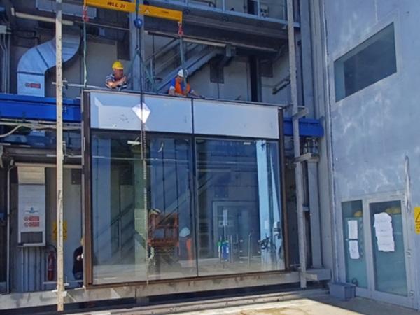
The experimental testing took place at the Permasteelisa laboratory in Vittorio Veneto, Italy, which offers the capability to test full-scale facades with dimensions of approximately 10m in width and height. The specimens were secured to a steel support structure comprising of an intermediate movable "blue" beam, capable of movement in both the X horizontal and Y vertical directions within the plane (as depicted in Fig. 5a).
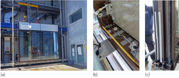
An instrumentation layout was designed to capture the in-plane and out-of-plane facade movements under quasi-static and dynamic loading. The monitoring system included a total of 31 displacement sensors: potentiometers and linear transducers, with 50mm, 100mm and 200mm stroke, to record the vertical and horizontal displacements of glass panels and framing system, including the hook/bracket connections to the seismic beam; draw wires, with 50mm measurement range, to monitor the diagonal and corner elongations of the frame. Laser sensors (200mm or 500mm detection) were used for monitoring the movement of the seismic beam. In addition, accelerometers were used to measure the accelerations, while strain gauges were employed to record strains. These measurements were taken on the glass, specifically in the vicinity of the setting blocks, as well as on one bottom corner of the frame system.
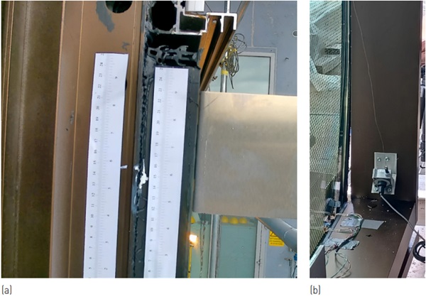
As only the external mullions could be monitored visually, five cameras (GoPro, digital cameras) were positioned to cover the length of the silicone of the 9x9mm² unit. The cameras were moved to the mullion of the other unit (27x9mm² or 20x9mm²) once the silicone failure was reached. Adhesive rulers were attached along the perimeter zone to monitor the relative movement of the silicone. This was done by analyzing the recorded videos. Additionally, laser sensors were employed in the bottom corner to monitor the relative displacements between the glass and frame in both the horizontal and vertical directions. Finally, the potential propagation of the crack in the silicone was monitored visually, measuring any increase with rulers. Besides the visual monitoring of the edge, an additional camera was placed in the front of the test set up to record the behaviour of the overall unit.
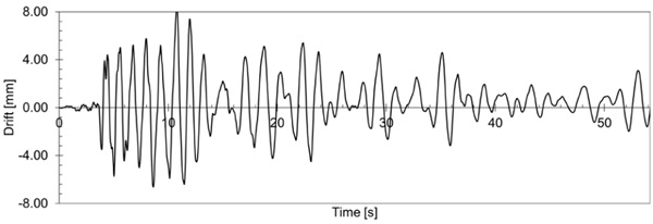
The testing process consisted of multiple phases for the four units, with the goal of inducing failure in the silicone joints through dynamic or monotonic seismic loading. The dynamic testing encompassed two main approaches. (1) Crescendo tests based on the AAMA 501.6 [2001] standard. These tests involved gradually increasing the amplitude of loading up to a maximum of 72mm. (2) Simulation of earthquake records, both far field and near fault, through inter-storey drift time series. These time series were generated through non-linear numerical analysis of a multi-story building subjected to seismic events such as Friuli 1976, Umbria-Marche 1997, and Christchurch 2011. An example of such a time series can be seen in Fig. 6.
To achieve higher drift values, quasi-static monotonic testing (horizontal in-plane) were performed until 250mm. Testing was interrupted after each loading case to allow for visual inspection of the free mullion. Each specimen was also subjected to lowintensity dynamic tests (both time-history and crescendo) for modelling calibration purposes. After testing the units, a full deglaze is planned to determine the exact initial joint dimension, the depth of failure (if any) and their location.
3. Preliminary observations
The first tested units (configuration 2, frames with seismic detailing at 9mmx9mm and 20mmx9mm) underwent several tests (dynamic and quasi static) without noticing any damage. Therefore it was decided to induce an artificial damage to the 9mmx9mm and monitor its potential propagation upon further exposure to seismic events. As the importance of the damage was gradually increased, it appeared that the silicone was resisting very well and that generating different failure mechanisms with the frames having seismic detailing would be impossible with the planned testing. Therefore, the remaining 3 units were restrained to avoid their relative rotation with respect to the slab and to amplify the frame distortion. Table 3 presents a summary of the testing sequence implemented for each unit, along with the observed damage.
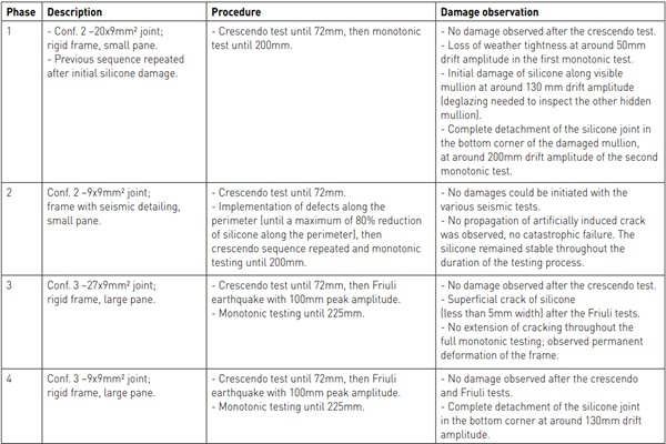
The initial observations from the experimental testing allow for drawing preliminary conclusions. As expected, the design of the frame system significantly influenced the mechanisms occurring during seismic events. It was observed that in the case of a rigid frame system, the failure of the silicone joints may occur first. While, as observed during Phase 4 of the testing (see previous table), when a more flexible frame system was adopted with appropriate detailing to accommodate higher displacements during earthquakes, the behavior of the frame system governed the failure mechanism. This involved detachment of the unit from the brackets, which might have occurred at displacements greater than the maximum allowable limit set by the beam (> 225mm).
It is important to highlight that the formation of initial cracking along the mullion and the complete detachment of the silicone in the corner (shown in Fig. 7) occurred at drift values of approximately 3.3% and 5.2%, respectively. These drift values are considerably higher when compared to the code-compliant drift values for assessing the safety level of facades, which range around 1% according to the experimental procedure defined in the Japanese code [JASS14 1996]. Furthermore, it is worth noting that the observed failure of the silicone joints did not result in a catastrophic failure of the unit, indicating that the overall safety was not compromised.
4. Discussion and next steps
At the time of writing of this paper, the post processing of data is still under development, which does not allow to draw full conclusions yet. First observations seem to indicate that a frame with seismic detailing may be beneficial to reduce the strain on the sealant. On the other hand, rigid frames evidenced a different failure behaviour for the various tested units. At this stage it is however not possible to confirm and understand a potential influence of the joint aspect ratio, the glass pane dimensions nor the strain rate. Initial results evaluating (induced) crack propagation were encouraging as no crack propagation was observed during subsequent testing of the damaged unit, however further study of the crack formation during the seismic event is needed to confirm identified failure criterium. Following these observations, deglazing and additional FEA introducing more accuracy in the model is planned to be able to reproduce the experimental observations and eventually be able to derive criteria for failure prediction and suitable design strength values as well as joint dimensioning guidelines optimizing a response to seismic events. More results will be shared during the presentation.
5. Acknowledgements
The authors wish to thank Permasteelisa’s experts: Giampiero Manara, Innovation & Technology Manager and Chief of Structural Calculations, Matteo Dazzan, Test & Lab specialist, Gianluca Casagrande, I&T specialist of the experimental measurement acquisition system and all the Test&Lab employees, for the fruitful and creative discussions. Enabling the victory over the silicone.
6. Disclaimers
THIS INFORMATION IS OFFERED IN GOOD FAITH FOR YOUR CONSIDERATION, BUT WITHOUT GUARANTEE OR WARRANTY (EXPRESS OR IMPLIED), AS ANALYTICAL CONDITIONS AND METHODS OF USE OF THE INFORMATION AND MATERIALS DESCRIBED HEREIN MAY VARY AND ARE OUT OF DOW'S CONTROL. ALTHOUGH THIS INFORMATION IS BASED ON DATA DOW BELIEVES TO BE RELIABLE AND ACCURATE, WE DO NOT INTEND FOR YOU TO USE, AND YOU THEREFORE SHOULD NOT CONSTRUE, THE CONTENTS OF THIS DOCUMENT AS BUSINESS, TECHNICAL OR ANY OTHER FORM OF ADVICE. WE RECOMMEND YOU DETERMINE THE SUITABILITY OF THE INFORMATION AND MATERIALS DESCRIBED HEREIN BEFORE ADOPTING OR USING THEM ON A COMMERCIAL SCALE. DOW ASSUMES NO LIABILITY IN CONNECTION WITH THE USE OF THIS INFORMATION ® ™ Trademark of The Dow Chemical Company ("Dow") or an affiliated company of Dow
7. References
AAMA 501.6, Recommended Dynamic Test Method for Determining the Seismic Drift Causing Glass Fallout from a Wall System. Publication No. AAMA 501.6-99, American Architectural Manufacturers Association, Schaumburg, Illinois, 2001
Baird A, Palermo A, Pampanin S, “Facade damage assessment of multi-storey building in the 2011 Christchurch earthquake, ” Bulletin of New Zealand Society and Earthquake Engineering, vol. 44, no. 4, pp. 368–376, 2011
Bârnaure M, Voiculescu M, “The seismic behaviour of curtain walls: An analysis based on numerical modelling,” Math. Model. Civ. Eng., vol. 9, no. 4, pp. 1–8, 2013
Bianchi S, Lori G, Hayez V, Schipper R, Pampanin S, Overend M, Manara G, Klein T, Seismic testing and multi-performance evaluation of full-scale unitized curtain walls: research overview and preliminary results, Fifth International Workshop on the Seismic Performance of Non-Structural Elements (SPONSE), 2022
Diana FEA, www.dianafea.com 2023
Dow, DOWSIL™ 993 Structural Glazing Sealant Simulation Data Sheet, www.dow.com, accessed 21st April 2023
Dow, DOWSIL™ 983 Structural Glazing Sealant Simulation Data Sheet, www.dow.com, accessed 21st April 2023
Huang B, Chen S, Lu W, and Mosalam KM, “Seismic demand and experimental evaluation of the nonstructural building curtain wall: A review,” Soil Dyn. Earthq. Eng., vol. 100, pp. 16–33, 2017
Kimberlain J, Hayez V, Feng J, Mirgon M, SSG and Seismic Design Boundaries in Advanced Modeling, Façade Tectonics, 2022
Lalas P., “Curtainwalls’ resistance of building movements, including seismic effects,” Current Trends in Civil & Structural Engineering, pp. 1–6, 2022.
Nuñez Enriquez DA, Seismic Performance of Glazed Curtain Walls Connections: Experimental Testing and Finite Element Modelling, Master of Science Civil Engineering, Delft University of Technology, 2022
Sitte S, Hayez V, Kimberlain J et al, Structural silicone joint behaviour study for cold bent glass. Glass Struct Eng 6, 39–63 (2021). https://doi.org/10.1007/s40940-020-00125-7JASS14, “Japanese Architectural Standard Specification Curtain Wall,” Architectural Institute of Japan, 1996


Comments
As the anticipated maximum strain in the sealant joint is reached, resulting from the deformation of the sealant joint, tension stress in an out-of-plane direction will arise, ultimately leading to the detachment of the glass.
Really insightful paper — I appreciate how it combines finite element analysis with real experimental validation. The detailed breakdown of joint dimensions and frame flexibility provides a clearer picture of how curtain wall systems behave under seismic stress. Research like this is crucial, especially for urban areas in seismic zones, where safety and durability must go hand in hand with aesthetics. It’s interesting to see how different industries focus on structural resilience — whether in architecture or even infrastructure maintenance, like what companies such as miami shores plumbing handle on a local scale. Both fields show how essential strong foundations are for protecting communities.