

AUTHORS: Jörg Leicher, Anne Giese
Gaswärme-Institut e.V, Essen, Germany, leicher@gwi-essen.de
PROCEEDINGS OF ECOS 2012 - THE 25TH INTERNATIONAL CONFERENCE ON EFFICIENCY, COST, OPTIMIZATION, SIMULATION AND ENVIRONMENTAL IMPACT OF ENERGY SYSTEMS
(JUNE 26-29, 2012, PERUGIA, ITALY)
Abstract:
Melting glass is a very energy intensive process, with process temperatures of more than 1600°C required to melt the raw materials in the furnace. Such high temperatures are usually achieved by intensive air preheating and near stoichiometric conditions. This leads to a significant production of nitrous oxides (NOX).
As the emissions of nitrous oxides are regulated be increasingly stringent environmental legislation, the glass industry is very interested in combustion techniques which reduce NOX emissions without resorting to expensive flue gas treatment while maintaining the glass quality.
In the steel industry, the so-called flameless oxidation (FLOX) combustion concept is firmly established as a state-of-the-art primary technique to reduce NOX formation in furnaces. This technology uses high momentum jets of fuel and oxidizer to generate an intense recirculation of hot, but chemically inert flue gas into the reaction zone. By mixing flue gas into the reaction zone, its shape changes from a quasi-twodimensional flame front into a three-dimensional reaction volume.
A much more homogeneous temperature distribution is obtained while the formation of hot spots can be avoided, thus significantly reducing thermal NOX emissions. The name “Flameless Oxidation” derives from the fact that no visible flame can be observed with the naked eye since the local OH concentrations are very low due to the large amounts of recirculated flue gas. Experience from the steel industry shows great promise for the introduction of this technology into other industrial sectors as a means to reduce nitrous oxide emissions.
In the course of a German research project, the Gaswärme-Institut e.V. Essen (GWI) in cooperation with several industrial partners investigated how to best introduce the flameless oxidation technique to glass melting furnaces equipped with recuperative burners, so-called unit melters. A furnace of a project partner, producing glass for compact fluorescent lamps, was chosen for conversion to FLOX burners.
Initially, there was some skepticism with regards to the applicability of a combustion process without a visible flame in a glass furnace, as normally, a slow, highly luminous flame is considered desirable in such furnaces. Also, the high gas velocities in the fuel and oxidizer jets carry the risk of blowing dust from the batch into the central recuperator. Thus, a careful design of both the new burner system as well as their positions in the furnace was necessary to avoid high gas velocities immediately above the glass bath.
In a first step, a FLOX burner system for recuperative glass melting furnaces was developed and optimized at GWI, using CFD simulations. This prototype was then tested at GWI’s semi-industrial test rig in order to verify that the new design was able to comply with the required NOX emissions limit. Compared to the burner originally mounted in the glass furnace, a reduction of almost 60 per cent was achieved.
In order to reduce the downtime of the furnace to a minimum, the exchange of the burners was planned using CFD simulations. Different configurations were simulated in order determine potential problems and an optimum burner set up was found, which was subsequently implemented on the site.
The retrofitted plant has been in operation for five years now still maintaining to produce the same glass quality as before the retrofit. The NOX emissions, on the other hand, were reduced by about 50 per cent. In addition the energy consumption of the process was reduced because an optimized burner positioning and more stable combustion allows for lower air ratios in the furnace, thus reducing fuel consumption.
Keywords:
Glass Melting Furnace, Flameless Oxidation, NOX Emissions
1. Introduction
The melting of glass on an industrial scale is a very energy-intensive process which, depending on the glass quality being manufactured, can easily require process temperatures of more than 1600 °C. These very high temperatures are usually achieved in glass melting furnaces by means of intensive pre-heating of the combustion air, either recuperatively (maximum air pre-heat temperatures around 800 °C) or regeneratively (maximum air pre-heat temperature 1400 °C).
These high temperatures, combined with a near-stoichiometric operation of the burners and long residence times due to the size of the furnaces and generally low flow velocities, often lead to a significant formation of nitrous oxides (NOX). As the emission of these pollutants is strictly regulated by emission laws, the glass industry is very interested in techniques to reduce NOX emissions without resorting to costly secondary flue gas treatment. Instead, techniques are preferred which reduce NOX formation in the furnace itself, of course without reducing the glass quality.
One such potential primary technique to reduce NOX emissions is the so-called flameless oxidation (FLOX) technology, which is already well-established in the steel industry. Other common names for this technology are mild or colorless combustion. This technology, first developed in the 1980s [1], uses high momentum jets of fuel and air to entrain large amounts of hot, but chemically inert flue gas and mix it with fuel and combustion air. In this manner, the shape of the reaction zone is changed: instead of an almost two-dimensional reaction front, a three-dimensional reaction volume is created in which the reactants are diluted by the hot exhaust gas.
The consequence of this change in the form of the reaction zone is that a much more homogeneous temperature distribution is obtained, without the temperature peaks usually found in conventional diffusion flames. As thermal NOX formation is highly dependent on local temperature, this much more homogeneous temperature distribution drastically reduces NOX emissions. Figure 1 shows a comparison between the standard and the FLOX modes of combustion while figure 2 shows flame images both in the visible and UV spectrum (using an OH chemoluminiscence method) of standard diffusion flames and FLOX combustion.
.jpg)
Click to enlarge.
Figure 1: Principles of standard combustion (top) and flameless oxidation (bottom). On the right hand side, the temperature evolution is shown [2].
The name Flameless Oxidation derives from the fact that due to the dilution of the reaction zone, there is no visible flame while operating in FLOX mode, as can be seen on the lower left hand side of figure 2. Nevertheless, complete consumption of the fuel gas is achieved, which can be shown by CO measurements in the exhaust gas.
The different shapes of the reaction zones are visualized by the OH* chemoluminiscence images shown on the right hand side of figure 2. While the standard combustion shows a zone of intense combustion near the burner outlet, the reaction zone in the flameless mode is lifted off the burner throat and shows a more even OH distribution.
.jpg)
Click to enlarge.
Figure 2 : Comparison of Standard (top) and FLOX (bottom) combustion modes in the visible and the UV spectrum
.jpg)
Click to enlarge.
Figure 3: FLOX mode as a function of the partial pressure of O2 [3]
As the intense mixing of the reactants with hot but chemically inert exhaust gas lifts local temperatures above the self-ignition limits, the local oxygen concentrations are reduced (cf. Fig. 3), leading to a unique form of combustion which is characterized by very homogeneous temperature and heat flux distributions, stable combustion behaviour and very low NOX emissions. Also, noise emissions are low compared to conventional burners.
While the FLOX combustion mode has successfully established itself as a method to reduce of NOX in many high temperature applications, the glass industry was hesitant to adopt this burner technology as flames in glass furnaces are traditionally highly luminous while the reaction zones in FLOX combustion are almost entirely invisible.
However, results from a previous research project called EURONITE [4] were promising enough that a glass manufacturer (OSRAM GmbH) and a burner manufacturer (Hotwork International) could be convinced to participate in a research project called GlasFLOX which investigated the applicability of FLOX technology for glass melting furnaces.
2. The GlasFLOX Project and Test Rig Experiments
One of the defining characteristics of flameless oxidation burners is the very high momentum of the fuel jets and combustion air. It is therefore obvious that FLOX burners can only be applied to glass furnaces with recuperative air preheating because only in this configuration the required high velocities jets for the combustion air can be achieved. A schematic of such a recuperative glass melting furnace is shown in Figure 4.
.jpg)
Click to enlarge.
Figure 4: Schematic of a recuperative glass melting furnace
The primary objectives of the GlasFLOX project were to design a FLOX burner for operation in glass melting furnaces which would produce less than 500 mg/Nm3 NOX and at the same time show good behavior at partial loads. Of course, maintaining the quality of the glass was of utmost importance.
In a first step, a 500 kW FLOX burner for application in glass furnaces was designed. CFD simulations were carried out to find the optimum geometry for the burner which was then manufactured and extensively tested at one of GWI’s semi-industrial test rigs in order to validate that the targeted NOX emission levels were achieved.
Figure 5 shows a comparison between the original (HWI) and the newly designed GlasFLOX burner systems. In the lower half of the figure, the CFD-calculated velocity distributions can be seen. As intended, the reduced section area leads to much higher air velocities which impart a very high momentum to the gas/air jet. The higher velocities cause higher pressure drops in the burner but these were found to be within acceptable limits.
.jpg)
Click to enlarge.
Figure 5: Comparison of the standard nozzle brick and the newly designed GlasFLOX nozzle brick with simulated velocity distributions
Numerical simulations of the original and the GlasFLOX burners showed that lower maximum temperatures were achieved in the case of the flameless oxidation burner while the temperatures of the flue gas remained almost the same. These findings were validated by measurements. The experimental investigations of both the original and new burner system in GWI’s test rig prove that the GlasFLOX system was able to comply with the target emission values for NOX (cf. Figure 6), which was already significantly below the legal emission limits of 800 mg/Nm3.
Due to these very promising results, the retrofit of an existing glass melting furnace with the new GlasFLOX burners was planned.
.jpg)
Click to enlarge.
Figure 6: Measured NOX emissions of the original (HWI) burner and the new GlasFLOX burner
3. Conversion of a Glass Melting Furnace
The glass melting furnace which was to be retrofitted with GlasFLOX burners is a side-fired furnace with ten burner positions, which are connected to a central recuperator to recover waste heat from the exhaust gas in order to preheat the combustion air. A sketch of the plant is shown in Figure7.
The process operators did not want prolonged downtimes of the plant and hence loss of production, which is why the retrofit campaign was planned in advance aided by CFD simulations of the furnace. Several configurations were simulated and evaluated.
In a first step, only four of the ten existing burners were substituted with GlasFLOX burners, those close to the batch inlet. However, simulations showed that this configuration led to increased gas velocities near the batch and the flue gas ducts. High velocities in this area are not desirable as this may lead to carry over from the dust-laden batch material into the recuperator which may cause increased wear and tear or even damage of the recuperator.
Therefore, a second configuration was investigated in which all but the two burners closest to the batch inlet were swapped with GlasFLOX burners. In this way, low velocities close to batch inlet and flue gas ducts can be maintained, minimizing the risk of dust carry over into the recuperator. Figure 8 shows the various steps of the retrofit, while Figure 9 shows the calculated velocity distributions immediately above the glass melt for the various configurations [5, 6].
Also, several different alignments and configurations of the burners were simulated numerically in order to avoid collisions of the jets which might cause increased turbulence and hence disturbance of the glass bath and potential dust-ups. This was not a problem before as the burner exit velocities of the original burners were relatively low, but became important when using the flameless oxidation burners with their much higher jet momentum. It was found that a burner alignment of 5 degrees off the burner axis was well-suited to avoid these issues.
.jpg)
Click to enlarge.
Figure 7: Schematic of a glass melting furnace
.jpg)
Click to enlarge.
Figure 8: Burner configurations for the various retrofit phases
In the next phase, the conversion of the furnace was carried out based on the findings of the CFD simulations. Eight standard burners were replaced with GlasFLOX burners with the two burners closest to the batch inlet remaining untouched in order to maintain low gas velocities near the batch. After the retrofit, pollution emission measurements were performed in order to evaluate the impact of the new burner system on NOX emissions.
Comparisons with NOX emission measurements taken prior the retrofit show a reduction of about 45% while maintaining constant fuel consumption and, most importantly, glass quality. Also, condensation in the flue gas ducts was found to be reduced by about 30%. Due to the increased combustion stability inherent in the FLOX technology, it was even possible to reduce the excess air ratio.
.jpg)
Click to enlarge.
Figure 9: Simulated velocity distributions near the glass bath for the various retrofit phases
After nearly five years in operation, the plant operators are very pleased with the new burner system. NOX emissions remain low, and there was hardly any corrosion to be found at neither the burner tips nor the nozzle bricks. The burners themselves require less maintenance than the original equipment.
While there were some reservations in the beginning to the use of high momentum burners in a glass furnace due to the fear of increased dust-ups, this was found not to be the case. In fact, the amount of dust in the flue gas decreased slightly.
4. Conclusion
In the course of a research project carried out by the Gaswärme-Institut in cooperation with several industrial partners, namely OSRAM GmbH and Hotwork International AG, introduced the flameless oxidation technique into the glass industry.
In the beginning, this combustion concept which has already been successfully implemented in various high temperature manufacturing processes, was regarded with some scepticism due to the lack of a visible flame and the requirement for high velocity gas flows in a glass melting furnace.
However, using both experimental and numerical techniques on a lab-scale, it could be shown that this combustion concept can be successfully adapted for use in glass melting furnaces.
The subsequent conversion of the furnace to flameless oxidation operation was prepared beforehand by extensive use of CFD simulations in order to minimize the downtime of the plant. The retrofitted furnace has been operating for about five years now, with an excellent operational track record.
NOX emissions are about 45% lower than before the conversion, while maintaining the same glass quality as before. While fuel consumption has not decreased, it is possible to reduce the excess air ratio in the furnace since FLOX combustion is much more stable than conventional combustion systems.
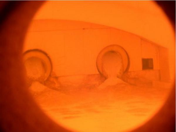
.jpg)
Click to enlarge.
Figure 10: View into the GlasFLOX glass melting furnace
5. References
[1] Wünning, J.G.: Flammlose Oxidation von Brennstoff, PhD Thesis, RWTH Aachen, Germany, 1996
[2] Wünning, J.G: FLOX-Flameless Combustion, Thermprocess Symposium Düsseldorf, Germany, 2003
[3] Milani, A.: “Mild Combustion” techniques applied to regenerative firing in industrial furnaces, 2nd International Seminar on High Temperature Combustion, Stockholm, Sweden, 2000
[4] Flamme, M.; Kösters, M.; Scherello, A.; Kremer, H. and Boß, M.: Experimental Study of Heat Transfer Intensification in Glass Melting Furnaces. Final report of task 2.2 of the EURONITE project (JOE3CT970083). Gaswärme-Institut e.V. Essen, Germany, 2000
[5] Giese, A., Konold, U., al-Halbouni, A. Görner, K., Schwarz, G., Köster, B.; Application of Flameless Oxidation in Glass Melting Furnaces, 7th International Symposium on High Temperature Air Combustion and Gasification, Phuket, Thailand, 2008
[6] Scherello, A.; Konold, U. and Görner, K.: Anwendung der flammenlosen Oxidation für Glasschmelzwannen mit rekuperativer Luftvorwärmung – GlasFLOX®, 23. Deutscher Flammentag, 12.-13. September 2007, Berlin, VDI-Bericht 1988


.jpg)
.jpg)
.jpg)
.jpg)
.jpg)
.jpg)
.jpg)
.jpg)
.jpg)
.jpg)