First presented at GPD 2017
Abstract
Following a short overview outlining key design objectives, the fabrication process of an opaque composite glass panel is described in detail. The assembly is formed of ceramic coated, heat treated glass and smaller backing panels laminar bonded using a silicone adhesive. The backing panels are segmented forming multiple connection points. Whilst mainly focusing on fabrication technologies and the QA-QC procedures utilized, this paper will also discuss material properties and structural considerations to provide the reader with a comprehensive overview.
Objectives
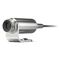
The composite panel was developed for a project specific requirement of cladding components to form a uniformly opaque and seamless glass surface. Mechanical fixings (Figure 1), protruding the glass surface or shining through a colored interlayer or ceramic print, have been agreed to be visually non-desirable. A further requirement is the necessity to utilize the composite in an overhead application. Consideration of the post-breakage behavior for glass in this configuration typically leads to laminated safety glass. In combination with mechanical fixings or supporting elements sufficient in size and or number, stability following damage needs to be ensured.
With the visual intent, project particulars and safety considerations in mind, the following design objectives have been formulated. They serve as a coarse road map for the product development process.
- The cladding system should provide a uniform opaque surface in sizes up to 15 m x 3.2 m.
- Visual continuity of the surface is paramount. The surface should not be disrupted by localized components (i.e. mechanical fixings).
- Any supporting structure should avoid or minimize local stress concentrations in the glass.
- As the glass is fully opaque, mirroring is expected. To ensure an unhasty visual experience, a small and/or uniform deflection of the glass is required. This is understood to be a mixed task, requiring structural (deflections due to loadings), fabrication (off site tolerances) and installation (on site tolerances) input.
- Any weight reduction will help to reduce seismic loadings and minimize the structural requirements for the supporting structure.
- In case of glass breakage sufficient system redundancy is needed.
- For cleaning and maintenance the glass may be accessible.
- Considering a quantity of approx. 30.000 m² fabrication ideally allow for an automated process.
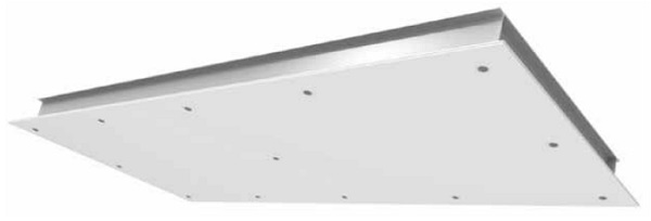
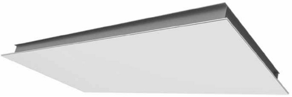
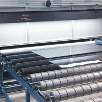
By substituting one glass ply with an aluminum backing panel, bonded using a silicone adhesive, a weight reduction of over. 30 % is possible. Silicone is selected as a suitable material to bond glass and aluminum backing panels. The laminar bonding provides redundancy in case of glass breakage and is able to transfer loadings safely. The system does not require additional mechanical fixings, providing a uniform surface (Figure 2). It is important to note that silicone in laminar application is outside current regulations (i.e. ETAG [1] or ASTM [2,3] or ASTM [2-4]).
The size of the backing panels is limited to manage thermal expansion between the individual bonding partners. This approach allows the design to be optimized for silicone thickness, however with decreased backing panel sizes the amount of connection points increases.
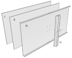
Every backing panel is attached to a supporting sub-structure via an adapter profile (iv.), mechanically fixed to the backing panel.
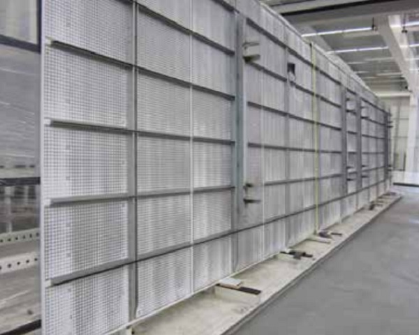
Figure 4 shows a 15 x 3 m tall composite unit. The unit has up to 80 individual backing panels bonded to the surface.
For the structural design of the glass panel, point loadings at the glass edge are identified as critical. The stress levels around the connection points are not critical for the glass.
Silicone adhesive – material properties
For the intended use, a self-leveling silicone adhesive was developed. Processing times in mind, a two-component silicone was chosen. The material has been optimized for a laminar application. A variety of tests have been conducted to verify mechanical performance, long term flexibility, adhesion, curing parameters as well as pre-treatment options. This led to a design concept and application limits for selected bonding substrates and materials in direct contact with the adhesive.
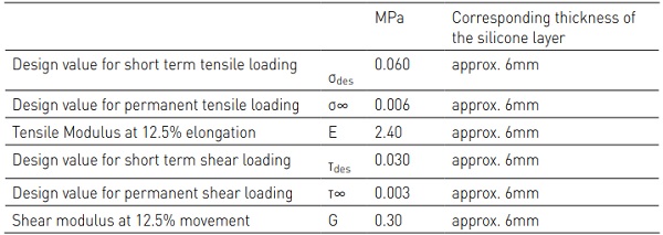
The silicone performance has been confirmed by independent laboratories on the basis of ETAG 002 [1], ASTM C 1184 [2] and ASTM C 920 [3]. These standards provided guidance when testing material behavior but require adaption to account for the intended laminar application. Lateral elongation is constrained, therefor the shear modulus is not equal a third of the Young’s modulus as assumed for linear applications. In Table 1 key material properties derived by testing are summarized.
Structural Design
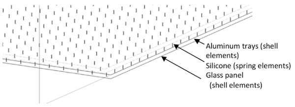
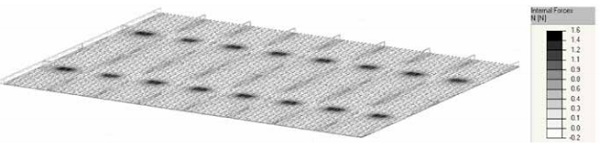
The silicone layer is depicted using spring elements (Figure 4). These elements are based on the parameters and design values summarized in Table 1 and its thickness. The glass and the aluminum panels are modeled using shell elements.
The spring forces are converted to stresses using the area substituted by a spring element. As apparent in Figure 5 the stresses in the silicone are not evenly distributed due to the varying stiffness of the backing elements. The verification concept accounts for the interaction of normal and shear stresses for short- and long-term loading. This approach allows for a detailed structural check of all components against dead, wind, seismic, temperature and maintenance loadings. More details on the structural assessment and design limitations can be found in [5].
Fabrication methods
The amount of backing panels provides the quantity of fixing points as every backing panel is required to transfer loadings back to the supporting structure in case of glass breakage. The fabrication process must allow for the positioning of the individual fixing points to tight tolerances. The maximum deviation of any point in the surface, measured from defined reference points was agreed to be within +/-2 mm.
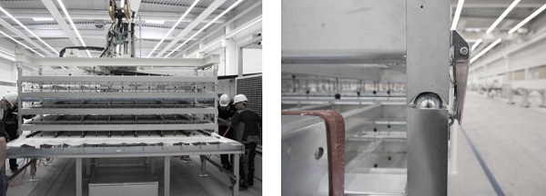
First concepts were trying to connect the panels via its folds to the supporting structure. Fabrication trials showed this approach to be hard to control. The selected design works on the basis of a connection pin, located in an adapter profile. The adapter profile is mechanically fixed to the aluminum tray. Using bespoke lifting frames, each holding a row of panels spanning over the short length of the glass it is possible to control the fixing point position within the required tolerances (Figure 7). Rotations of the aluminum panel do not influence the accuracy of the fixing point position.
The lifting frames require fabrication to tolerances smaller +/-2mm as all equipment and fabrication tolerances will sum up and eventually exceed the agreed tolerances. For the lifting and positioning frames fabrication tolerances below 1mm, measured from its setting out points are required.
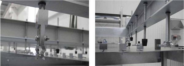
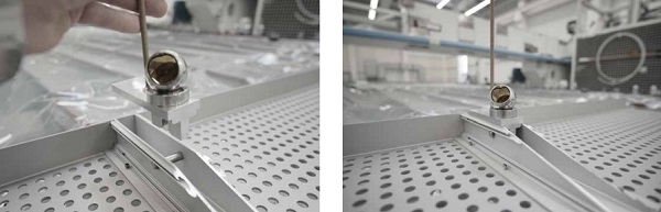
The frames are equipped with adapters tying into the actual connection bolts and with pressure elements pressing the panels into the silicone bed to ensure a defined distance between outer glass surface and connection bolt (Figure 8). The distance between glass and aluminum is maintained using silicone spacers, cast from the same silicone material used for the laminar application.
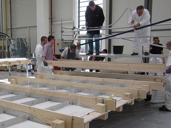
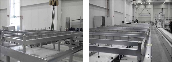
Whilst the lifting frame provides exact positioning for a row of panels, tolerances between adjacent frames require consideration as well. To ensure two neighboring frames are positioned within the agreed tolerances, processing tables are required (Figure 9). These tables are equipped with perimeter profiles receiving connector elements (Figure 10).
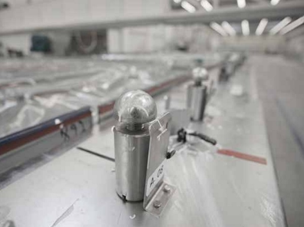
These connector elements can be positioned along the machine bed within a 1/10 mm. Following positioning of the adjustable connectors using a high precision measurement equipment the elements have been grout locked in position to eliminate the risk of position errors during mass production. The tables allow for exact positioning of the glass units, using setting out references. As glass in the sizes used for the process in itself is tolerance afflicted, a setting out edge has been agreed on. All glass tolerances have been pushed to defined joints. A flexible edge evacuation was designed, able to account for glass tolerances, minimizing any follow up works.
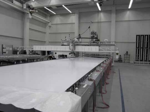
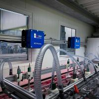
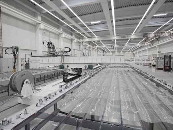
A bespoke silicone pump, designed for the processing of the laminar silicone was travelling along tracks to serve 16 processing tables (Figure 11). Following machine cleaning and positioning of the glass on the tables, the pump would apply the required amount of silicone. Once an area big enough for a positioning frame is applied, 2 operatives would place a frame on the machine bed and clamp it in position (Figure 12).
This process was repeated till the glass was fully clad. To reduce cycle time for the lifts, 5 lifting frames were combined to a process lift. The individual frames were connected with the same fast connectors used to secure the elements on the table. Once finished the composite panel was allowed to rest for 24 hours prior repositioning to allow the fabrication of a new unit.
The described fabrication equipment allowed for an accurate positioning of the components within the allowable silicone processing time of 20 minutes. It was possible to successfully fabricate 1750 façade units in sizes 10-15 m x 3 m on the described fabrication line with prototype character.
Quality Assurance / Quality Control
Fabrication on large scale when utilizing new methods and materials needs a strict quality assurance and control system. To mitigate human error all manual cleaning processes have been replaced by automated approaches. The glass was machine washed, the aluminum panels were delivered packed from the anodizing plant and plasma treated prior processing.
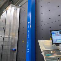
All system relevant parameters (e.g. surface treatment method, adhesion, mechanical strength) are trialed and tested prior implementation into the process and checked in parallel to fabrication to ensure consistent quality. Dimensional control is carried out on the composite element on the processing tables, measuring the actual bolt locations to identify deviations.
Summary
The fabrication process for a composite glass panel has been described in detail. Key aspects considered in the development process were outlined. It has been shown that it is possible to develop and implement new technologies and methods on a project basis. When approaching new technologies an open mindset for all parties involved is paramount.
References
(1) EOTA ETAG 002-1, Structural Sealant Glazing Systems Part 1. 2012.
(2) ASTM C 1184-13, Standard Specification for Structural Silicone Sealants. 2013.
(3) ASTM C 920-11, Standard Specification for Elastomeric Joint Sealants. 2011.
(4) ASTM C 1401-09a, Standard Guide for Structural Sealant Glazing. 2009.
(5) Doebbel, F.; Müller, U.; Teich, M.; Marinitsch, S.: Nobel laminar silicone application. In: Challenging Glass 4 & COST Action TU0905 Final Conference. Lausanne, 2014, pp 347-352.