This paper was first presented at GPD 2019 by Jon Kimberlain, Lawrence D. Carbary Pierre Descamps, Valerie Hayez Jie Feng from Dow Silicones.
The practice still holds challenges with a concern of how a permanent load due to bending can impact the durability of structural silicone sealants. To date, design practices used in cold bending relies on classical mechanical models based on purposely low average allowable stresses. However, when using finite element analysis (FEA), these average stresses can indicate stress distribution where regions of the sealant joint are well above the average allowable stress.
Different cold bent glass designs were investigated for their structural performance through FEA. A representative lab scale test was also developed to evaluate the structural silicone used in the cold bent glass. Long term tests were performed to monitor the change in the structural silicone joint to assess its durability by coupling the loading level to the rate of deformation over time. Testing included the use of a high speed camera to monitor the deformation of the sealant during rupture and crack propagation process. Ultimately, the analysis yields more insight to better predictive models for design criteria of structural glazing cold bent glass.
Introduction
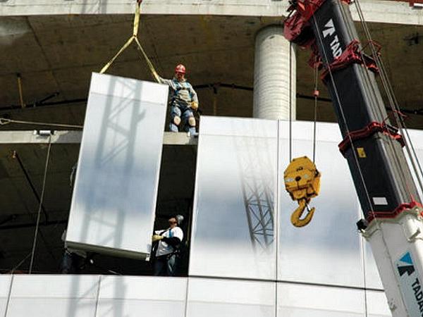
Cold bent glass in structural glazed facades have now been in service for over a decade without noted issues of leakage or structural failures. The façade on past projects used a cold bending technique to provide a curvilinear appearance as the tower section of the building twists along the vertical axis. The twisting appearance was achieved by introducing a bend into flat curtainwall units, pinning the bent corner to maintain the curvature while the remaining corners are installed in plane.
The post rationalization of the design was documented in a research paper done by façade industry collaborators [1] The research used mechanical means to determine the potential permanent load distributed to the sealant by the glass deformation followed by Finite Element Analysis of the potential for curvature in the frame and glass. The measurements were then incorporated into small scale IG units and tested to ASTM E2188 [2] for durability testing.
Initial criteria for designing the allowable cold bending stress on the structural silicone was based within the guidelines set by ASTM C1401[3] and ETAG 002[4]. A 24 mm thick insulating glass unit (6-12-6) measuring 1500 x 3000 mm was held by three corners and the unsupported corner was bent to the desired deflection. The force was measured.
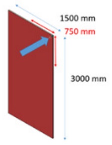
It was then assumed that the force would be uniformly distributed from the corner to the dimension of half of the short span, 750mm from the corner along the short and long span for a total of 1500 mm in length. Figure 1 provides an illustration. The dimension of the silicone in would then be calculated to meet design criteria to keep this plate in a long term cold bent deflection. Typical silicone stress is designed at 7000 Pa and this is an extremely simple and conservative approach.
Today, with parametric design, the use of Finite Element analysis is driving towards more comprehensive methodology in design for cold bending. An investigation was conducted to understand the impact of the extent of bending on durability of structural silicone joints above and beyond the original simplistic approach taken previously.
The investigation included building simple physical models with strains held at different levels and then measuring the resulting strain of sealant which was monitored for failure over time. Models of the physical assemblies indicated a relationship of not only the impact of load on the durability of the sealant but magnitudes of strain.
Methodology is presented as an improved process for cold bent design relative to sealant durability. The study focuses on the sealant durability based on long term strains.
Physical Mock Up
Test specimens were fabricated to replicate the spring effect of a glass lite adhered with structural silicone to a metal mullion under cold bending. The specimen consisted of a 508mm by 508mm aluminum panel with a square section cut out in the middle. A 304mm by 304mm aluminum panel was attached around the perimeter of the cutout using a two-part structural silicone sealant. The sealant was then allowed to cure for 21 days. Glass was not used in the mockup because the focus is evaluating the silicone at failure. Glass breakage would be likely at the high strains needed to cause silicone failure.
The test apparatus consists of a fixture that clamps the corners of the larger aluminum plate at three corners. On the fourth corner, a pressure device with indenter is placed underneath which can strain the corner upwards while the other three corners are held static. The inner plate is oriented towards the bottom so that action of the strain replicates the spring effect of cold bending of the glass assembly onto the structural sealant joint.
The test assembly allows for measuring creep over time using linear displacement gauges by capturing change to the dimension of the joint as a function of time. Video was also captured during the test duration to monitor for rupture of the sealant as well as crack propagation
The test specimen was modeled with FEA to understand how well behaved the theoretical movements could predict actual test results.
Discussion of FE Model on Stress Distribution
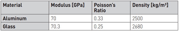
The Structural Silicone Glazing cold bent process is simulated in a lab scale test to assess its effect on the silicone, as shown in Figure 2. This test process is also modeled by FEA to understand the strain distribution in the silicone. In this test and simulation, a 6.35mmx304.8mmx304.8mm Aluminum plate (6061) is bonded by structural silicone (DC983) onto a flat 6.35mmx508mmx508mm Aluminum frame with a 233.75mmx233.75mm square cut out at center.
The bite of the SSG is therefore 26mm, and its thickness is set at 9.525 mm through 9.525mmx9.525mm polyurethane foam spacer. The Aluminum plate is used in this calculation, as it has very similar modulus and density as glass (see Table 1), but it will not break into small pieces as glass at excessive loading, which is much safer for carrying out the long term durability test.
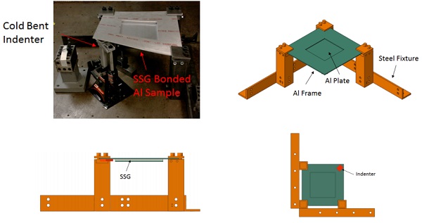
The bonded Al plates are then clamped onto a steel fixture at three selected corners, and the fourth corner is lifted by a hydraulic indenter. This lifting process is simulated in FEA model by assuming the hydraulic indenter is a rigid body.
It is important to note that the FEA of the silicone used elements that measured 1 x 1 x 1mm and the hyperelastic properties of this material are noted in table 2. Elements that are modeled as different sizes will have different results.

Physical Experiments
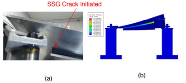
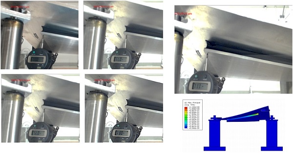
The bonded Aluminum sample was first bent to instant failure, as shown in Figure 3, and this bending process is also simulated by the FEA model. A Peak max principal strain of 123% was found to occur around the same location when SSG failure initiated, and this suggests that max principal strain can be used to estimate when SSG will fail in the cold bent test.
Results and Discussion
SSG Relaxion with Initial Peak Strain at 104.6%
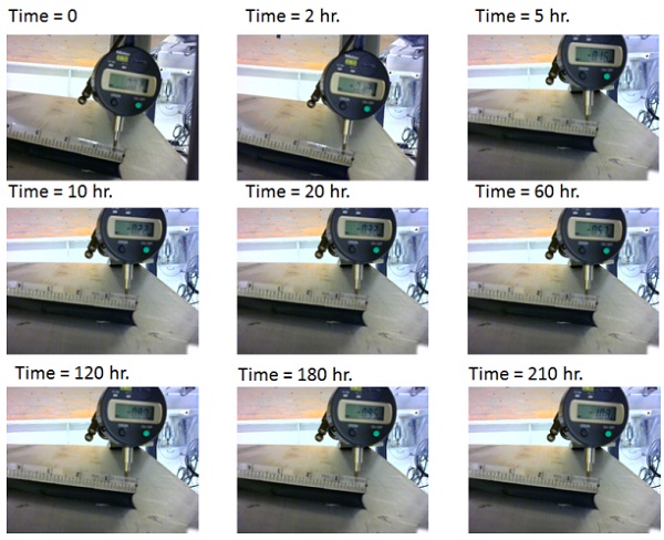
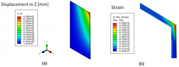
As 123% is likely to cause instant silicone failure, in the cold bent durability test shown in Figure 4, a peak strain was set to 104.6% through FEA calculation. Before the structural silicone reaches its durability limit, the bonded 6.35mmx304.8mmx304.8mm aluminum plate will gradually spring back due to the slow viscoelastic response of silicone overtime. This was measured by a precision dial indicator (see Figure 5).

This suggests that SSG relaxation will contribute to profile change in the cold bent component, and this profile change will increase over the time. Viscoelastic relaxation of the silicone will be visibly noticeable on a façade of a commercial building. Although a change would be gradual, it is likely to be an unwelcome surprise to the designer. This is another component in the understanding of the cold bent façade and durability.
Structural Silicone Failure with Initial Peak Strain at 104.6%
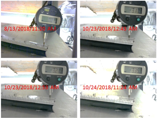
The SSG in the cold bent sample with initial peak strain set at 104.6% lasted about 1693 hours. A crack in the silicone initiated at the location of the FEA predicted peak max principal location as shown in Figures 6 and 7. This further confirms that peak maximum principal strain is a reasonable design criteria.
SSG Post Failure with Initial Peak Strain at 104.6%
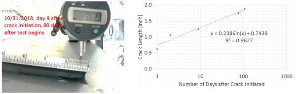
After the silicone joint developed a crack in the durability test, its crack growth was monitored for another 100 days. It was found that the crack in the silicone will continue to grow, in a logarithmic relationship with the time, as shown in Figure 7.
SSG Failure with Initial Peak Strain at 118.6%
By increasing the initial peak strain in the silicone to 118.6% in the cold bent test, it was found the silicone will only last 21 hours before it cracks. This suggests that higher peak maximum principal strain will reduce the durability in SSG in the cold bent process. Hence, to achieve a desirable durability for the SSG in the cold bent process, its peak principal strain needs to be controlled to a desirable range that will ensure no crack initiation or viscoelastic response.
Structural Silicone Design in Cold Bent Application
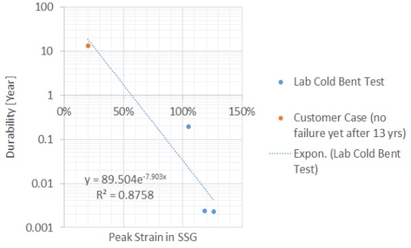
An existing cold bent application shown is also modeled for the peak strain in the SSG, figure 9. It is determined from FEA calculation, the peak strain is about 20% near the corner of the SSG. No structural silicone failure, structural or leakage has been observed in this cold bent application. A conservative silicone durability correlation can still be established by combining the strain prediction from the lab scale tests with strain prediction in this existing cold bent application, as shown in Figure 10.
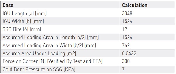
For the existing cold bend application, the averaged pressure in the SSG can be calculated by assuming most of bending stress is undertaken by the SSG near the cold bent corner, as shown in Figure 1 and 10. Hence, the averaged stress in the SSG can be calculated based on Equation 1. Detailed calculation is shown in Table3.
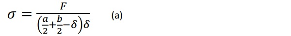
Where a is the IGU width, b is the IGU height, δ is the silicone contact width, F is the force required to generate SSG cold bending displacement. This is the simplistic approach to calculating average stress noted previously.
Conclusions
Previous methods to limit the amount of average permanent loading of structural silicone has worked in the past based on current success. The use of finite element analysis has shown the impact of potential localized peak stresses on durability of the cold bending process. Based on the above work, introducing estimates of peak localized displacement via strains has been demonstrated to provide insight in durability as demonstrated by physical test specimens.
Cold bent designs should avoid arcs of bending in the units that have excessive average permanent loads and localized areas of peak strain. Based on an existing project in service, limiting peak strains in typical element sizes of 1 x 1 x 1 mm to around 15% have a potential predicted service life of 30 years or above based on the materials tested and evaluated here. In addition, the mode of failure for excessive areas of strain are not shown to rapidly fail. Crack propagation after viscoelastic response was shown to be slow and would likely stop after the bending stress was relieved in the remainder of the silicone attachment.
An improved design process is proposed from current methodology using Finite Element Analysis for cold bending projects:
Determine a sufficient bite to keep average permanent loads at or below sealant manufacturers stated allowable stresses over the contact area of the actual bending. Standards do not exist to determine the material properties of a specific proprietary formulation. Communication with the silicone supplier on the material properties, how the properties were measured and the expected variation due to manufacturing process is essential to making a long-term successful design.
Model the assembly to determine the peak stresses and peak strains of the silicone using finite element software capable of modeling hyperelastic properties.
Adjust silicone joint design or moment of bending to keep peak strains at or below 15% of the original dimension of mesh element(s).
Obviously, there are caveats not specifically listed in the above methodology but should be understood and include the principle that appropriate material behavior models should be used, appropriate elements and mesh sizing should be used in the FEA and that in construction, tolerances and proper workmanship are critical for performance.
This modified methodology provides a greater measure of insight to durability to cold bending in an improved process for design beyond the current state of the art.
References
Besserud,K., Bergers, M., Black,A. J., Carbary,L. D., Mazurek, A., Misson, D., and Rubis, K., Durability
of Cold-Bent Insulating-Glass Units, Journal of ASTM International, Vol. 9, No. 3 Paper ID JAI104120 Available online at www.astm.org
ASTM E2188-10 Standard Test Method for Insulating Glass Unit Performance, ASTM International, West Conshohocken, PA, 2010, https://doi.org/10.1520/E2188-10
ASTM C1401-14 Standard Guide for Structural Sealant Glazing, ASTM International, West Conshohocken, PA, 2014, https://doi.org/10.1520/C1401-14
ETAG 002 Guideline for European Technical Approval for Structural Sealant, European Organization for Technical Approvals, Kunstlaan 40 Avenue des Arts, B - 1040 Brussels, Edition November 1999 3rd amendment May 2012.