Challenging Glass 6
Conference on Architectural and Structural Applications of Glass
Louter, Bos, Belis, Veer, Nijsse (Eds.), Delft University of Technology, May 2018.
Copyright © with the authors. All rights reserved.
ISBN 978-94-6366-044-0, https://doi.org/10.7480/cgc.6.2194
Authors:
- Benjamin Schaaf - Institute for Steel Construction, RWTH Aachen University
- Björn Abeln - Institute for Steel Construction, RWTH Aachen University
- Carl Richter - Institute for Steel Construction, RWTH Aachen University
- Markus Feldmann - Institute for Steel Construction, RWTH Aachen University
- Marcus Glaser - Department of Production Technology, Technische Universität Ilmenau
- Jörg Hildebrand - Department of Production Technology, Technische Universität Ilmenau
- Jean Pierre Bergmann - Department of Production Technology, Technische Universität Ilmenau

In present-day practice, monitoring the installation process and the utilisation of glass and hybrid components, e.g. glass/steel or glass/plastic, has become increasingly important. To date, the quality control options for built-in glass is limited. It is not yet possible to provide a clear short-term statement regarding a potential irregular stress; this may arise due to the incorrect assembly of a glass fitting, for example. There are no accepted standard procedures to evaluate the in-situ stress condition of a built-in glass. The intention of this paper is to address this gap with the aid of photoelasticity as an indirect measuring method in a coordinated way with numerical simulation based on finite element analysis.
To measure the two-dimensional qualitative stresses in glass and plastic components, a concept and a functional model for a mobile device, including user software, will be developed. By recording photoelastic measurements with this proposed mobile measuring unit, a qualitative statement about the glass stress behaviour for bonded and mechanical connections can be defined and converted into a quantitative statement via a correlation of experimental and numerical results. This article describes the associated framework for experimental investigations and numerical simulations for bonded and mechanical joints in glass constructions.
1.Introduction
Primary load-bearing elements made from glass or hybrid materials offer many possibilities in current and great potential for future construction projects. Hybrid structures, for example glass/steel or glass/plastic, allow a material-oriented load-bearing design to be produced, which utilises the ductility of the components and increases structural redundancies. As a result, the calculated safety factors for both the ultimate limit state and the residual load capacity, relating to glass breakage, can be increased.
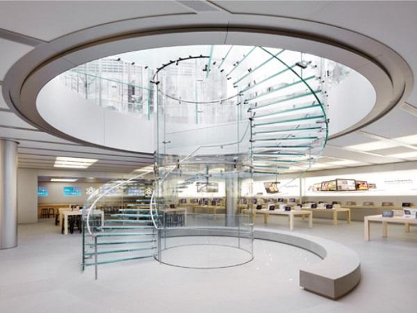
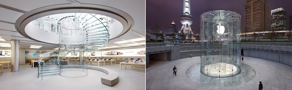
For the aspiration of modern architecture to further increase the transparency of buildings, the still innovative use of point-supported or bonded glass constructions offers a widespread possibility to reduce the area portion of the non-transparent attachment points to a minimum (see Fig. 1). In practice, such innovative structures require monitoring of the installation process and the utilisation of glass and hybrid components during their life cycle. However, to date, there are no accepted standard procedures to evaluate the in-situ stress condition of a built-in glass, particularly in relation to mechanical or bonded connections. The intention of the research project BiGla (AiF 2017) is to address this gap with the aid of an indirect measuring method.
Glass is a brittle material, so that failure does not appear slowly but suddenly and usually with no prior evidence. In the case of glass breakage, a subsequent damage analysis is often possible by visual inspection. However, it is not yet possible to predict damage and take countermeasures beforehand. This is due to the fact that so far no generally accepted non-destructive testing method has been available on the building structure, with which it is economically feasible to work with sufficient safety and accuracy in practice. Moreover, currently available test instruments cannot enable the combination of measuring planar qualitative stresses in glass components whilst ensuring mobility at the same time.
Due to the brittle material properties of glass, the influence of the surface quality on the load-bearing capacity and the resulting high dispersion of the strength parameters determined experimentally, conservative failure criteria and design strengths are specified in the standards. In addition, quality controls in the state of installation are only partly subject to current building regulations. For example, the stress state in the area of boreholes in point-supported glazing elements and in the area of adhesive joints cannot be reliably monitored over the service life. Unexpected stresses in the area around joints (e.g. due to constraints, incorrect installation, deformation of the structure, etc.) can lead to unforeseen breakage of glass elements.
The load-bearing behaviour of glass connections is generally very complicated and, therefore, care must be taken when planning, dimensioning and implementing point-supported connections. To date, however, the quality control options for built-in glass are limited. It is not yet possible to provide a clear short-term statement regarding a potential irregular stress state; this may arise due to the incorrect assembly of a point holderor the influence of environmental loads, for example. No detailed investigations or numerical analyses of accidental loading conditions and their effect on the bearing capacity of the point-supported connection have been undertaken.To enable premature detection of damages and, therefore, raise the construction safety, the implementation of a non-destructive measurement method and subsequent evaluation of the mounting conditions is a useful innovation.
2.State of the art in glass constructions
The following chapter gives a brief overview about the current state of the art in glass constructions with respect to joints. A differentiation is made between bonded and mechanical connections. With regard to the bonded joints, point-supported, line-supported and flat bonded joints are discussed.
2.1.Challenges of bonded connecting systems
Nowadays, the desire for maximum transparency plays an important role in the planning and construction of buildings. Due to the increasing use of glass, this requirement is met and at the same time more and more structural tasks are assigned to transparent building skin. As a result, it is not only single components that consist of glass, but also entire component groups such as complete facade systems, glass beams or supports. The conventional connections are usually made by means of metallic fasteners (mechanical connections), which, however, are discontinuity points during load introduction and generally restrict transparency.
Adhesive bonding technology can be used as an alternative joining method. Structural Sealant Glazing (SSG) systems are mostly used here. To date, ETAG 002 (EOTA 1998) is currently the only valid European guideline for the design of such facade constructions. The glazing element is connected to a support frame (stainless steel or anodised aluminium) by means of an all-round line-supported structural silicone bond. As an example, the facade of St. Paul's Square in Liverpool is shown in Fig 2.
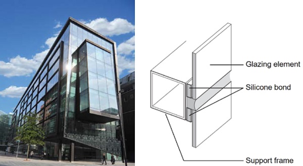
Adhesive bonded joints in structural glass construction have the advantage of a continuous load transfer, which can result in lower stresses than with conventional mechanical point supported connections due to larger load distribution areas. Without boreholes or visible metal elements these systems also increase the transparency of the building. In addition to line-supported bonded systems, point-supported bonds are also possible (as exemplarily show in Fig. 3(left)). They are often used for the vertical mounting of glass panes in interior fittings. In practice these adhesively bonded glass fittings are considerably less common than SSG systems.
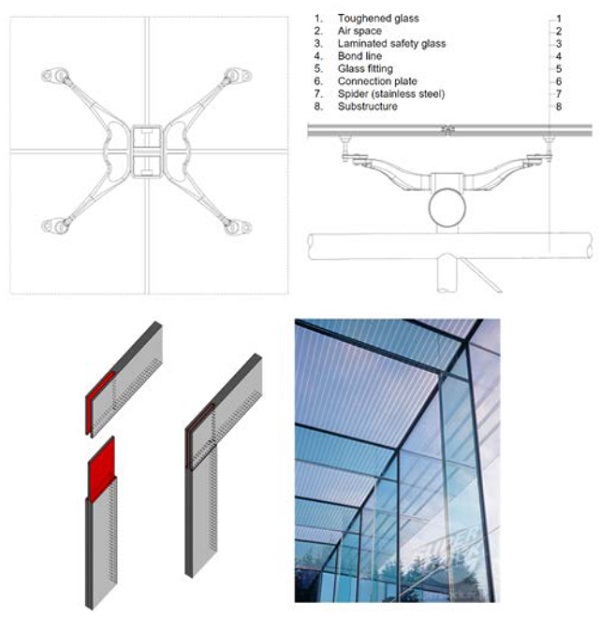
A third possibility of bonded joints are flat bonded joints. Fig. 3 shows the example of a column beam connection. The high shear strength of adhesive bonds is used to bear moments that manifest themselves in the adhesive joint as torsional moments. However, constructions of this type are problematic in their manufacture regarding shrinking and the prevention of air inclusions within the bond line.
After the installation of bonded facade elements, the resulting stress state in the glass in the area around the connection cannot be inspected. Although selective measurements can be carried out using the scattered light method, this method is very time-consuming while providing very few data output because a flat analysis is not possible. As already mentioned, there is an increasing demand of recording the changes of the stress state in the glass within the life cycle of a bonded glazing element as part of a monitoring purpose. For adhesively bonded joints those changes can result due to deflections caused by service loads, creeping of the adhesive or constraining forces.
Moreover, a statement of quality of the adhesive joint is to be made. Inhomogeneous adhesive layers, e.g. caused by air inclusions, locally poor mixing of the components or incorrect preparation, can lead to a disturbed stress state in the glass, which can be visualised using photoelasticity. Also local adhesion or cohesion failure within the adhesive (delamination, cracks), which cannot be seen from the outside, can have an impact on the stress state in the glass. With continuous monitoring also the load capacity losses due to aging of the adhesive can be recorded.
2.2.Challenges of mechanical connecting systems
Despite advancing developments in bonded glass applications, mechanical connection elements are still in use and mainly applied where the glass will bear its own weight as well as existing loads without any frames. The application of mechanical point fixed glazings offers therefore numerous possibilities such as facade, vertical or overhead glazings and railing cladding. However, there are various influence factors that may occur when using mechanical fasteners.
Especially the properties of the applied metal and plastic components, the applied tightening torques as well as the environmental temperature and moisture conditions or the creep effects over time of use. Due to the different influence factors and the different resulting loads, there is a demand for a differentiated, comprehensive and substantial consideration for each of the mounting systems.
Mechanical connection elements are classified in clamp mountings that can be used to bear glass panes at their edge and the group of hole drilled fasteners. Especially the last-mentioned connection elements are subjected to appearing forces and loads, as they require a material weakening as a result of the drilled holes. For this reason, these systems will be defined more closely below.
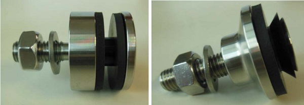
Point-fixed glazing systems are based on force and form fit while the main part of the loads will be transferred by ethylene propylene diene monomer (EPDM) or silicone separating interlayers that prevent the direct contact between glass and metal support. Depending on the stiffness of these layers, residual stress can be prevented as the glass pane is able to follow its natural bending line in a specific range. However, the essential characteristics of these interlayers depend on the environmental conditions, like for example ambient temperature or UV exposure.
Moreover, the direct contact between bolt and bore wall has to be prevented by using a bushing made of polyoxymethylene (POM) or polyamide (PA6). Furthermore, the hole drilled fasteners need to be differentiated into two categories. Firstly, disc holders with a cylindrical bore in the glass pane, in which a bolt will be inserted and fixed by the associated plate header and base. Secondly, countersunk holders which are on a conical bore integrated into the glass pane.
The support head is separated against the glass by a conical ring of POM or PA6 and can be inserted and aligned flush in the pane.In both cases surface damages, that will arise as a result of drilling and grinding, could be problematic because they increase the probability of fracture initiation and glass breakage. This means that the regions that are subjected to concentrated forces also show a high amount of defects and flaws.
The effect of the applied forces differs depending on the underlying connection system. The contact area of a clamp mounting system and the glass pane, for example, is not uniformly loaded. Therefore, certain areas of the EPDM ring will be subjected to a stronger load than others. The occurring transverse loads will be forward as a bearing stress into the bore wall. In mechanical connections with countersunk holes, the acting forces will be divided in radial and tangential tensions. Here, as a result of the brittle material properties of glass, it is particularly important to critically reflect the loads, that results in tensile forces. Moreover, disc holders as well as countersunk holders are subjected to the constructive challenge of a needed minimum distance to the support structure. Because of this distance the occurring transverse forces introduce additional moment loads (Winter 2014).
The application of photoelasticity makes it possible to measure and visualize these combined loading states as well as their effects. Here, it has to be accepted that in consequence of the special shape of mechanical connection systems only the area immediately at the edge of the holder can be examined. A statement about the loads directly at the edge of the hole is impossible.
2.3.Basics of photoelasticity
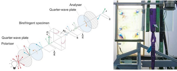
Photoelasticity is based on the visualization of the birefringence of optically isotropic or polarised light in transparent materials with the aid of a circular polariscope. Circularly polarised light is used to avoid the directional dependence of light, as it would occur with any other way of polarisation. In general, glass is not birefringent. However, loaded glass shows the property of birefringence due to the stress state in the glass.
The (monochromatic or polychromatic) polarised light vector splits into two perpendicular components when passing the specimen (see Fig. 5, left), which in this case is a loaded glass element. The directions of the vectors are equal to the principal stress directions in the material perpendicular to the glass thickness. The higher the difference of σ1 and σ2, the higher the retardation sbetween both components. The retardations is linked to the principal stress difference by the specimen’s thickness dand the so-called photoelastic constant C (Hildebrand 2010).
![]()
Dividing equation (1) by the wavelength λ yields to the phase shift δ and the so-called main equation of photoelasticity (2) is obtained:
![]()
The retardations is visualised within the polariscope by means of different colours (see Fig. 5, right). The higher the retardation, the more colourful the patterns appear and the higher the difference of the principal stresses (Feldmann 2017).
For a meaningful evaluation of the polarising filter images with this method, a flat stress state in the specimen over the thickness is assumed. Besides float glass, this method also works for thermally toughened glasses, but it is not possible to draw a direct conclusion about the practical stress state in the glass. To achieve this, the results of the measurement must be converted, taking into account the knowledge and experience of the boundary conditions and, for example, using numerical methods, in order to obtain the distribution of the "true" values in the glass.
This method is suitable for assessing the stress state in transparent, bonded materials as well as for steel-glass, wood-glass and plastic-glass joints. By visualizing the principal stress differences, it is possible to qualitatively assess the stress in the area under investigation. The evaluation of the main stress differences allows statements to be made about the degree of loading, but no statements can be made about the principal stress values - a quantitative evaluation is not possible without the use of other concepts and methods.
3.Approach of the research project “BiGla”
Nowadays, the application of measuring devices currently available is limited to laboratory conditions and not sufficiently mobile or limited to a very small measuring range. For example, one way to measure stresses in the glass is with the help of the so-called “Scatterd Light Polariscope” (SCALP, GlasStress Ltd.). This device uses the method of scattered light to receive information on the actual stresses in the glass. A light beam is scattered or radiated laterally to the direction of light from the glass particles. The beam path becomes visible to the outside. This is called the "Tyndal Effect". In a birefringent body it is possible to draw conclusions about the state of stress by observing the Tyndal Effect (GlasStress 2013). The core property of the SCALP is the direct measurement of stresses over the entire glass thickness with a high measurement resolution.
This is suitable, for example, for determining the prestress of thermally toughened glasses. However, this method is only suitable for punctual measurements (local), since the laser beam used scans only a very small area (diameter 0.2 mm). In order to gain an insight into the stress state in the area around a connection (rather global view), many local measurements would have to be taken, which then would have to be combined to an overall picture. This is time-consuming with simultaneous low information density. In addition, measurements must be taken in several directions in order to determine the actual stress level (e.g. in the form of principal stresses). A special contact liquid must be used for measurement. This makes measurement of vertical glazing elements very difficult.
Therefore, current solutions for stress measuring are not suitable to be used in-situ. Within the scope of the research project BiGla (AiF 2017), a concept and functional model for the application of a mobile device for measuringqualitative flat stresses in glass components based on photoelasticity including application software is to be developed.Major advantage of this method is the flat analysis of facade elements instead of local measurements. An insight into the stress state of complete glazing elements would thus be possible in real time. The measuring system - consisting of software and hardware - should be able to adapt to the spatial and local conditions of the object. High mobility is therefore necessary.
For this purpose, it is needful, for example, to adapt the fixation of the measuring device to the measuring object. The measurement will take place when installed and non-destructive. Using this mobile device possible critical points, the causes of faults, cracks or overloads in glass components can be quickly identified. This means that possible damaged areas that cannot be detected by current evaluation methods can be reliably found and repaired at critical level. Within the project experimental investigations and photoelastic analysis in combination with numerical simulations have to be carried out, which will be presented in the following sections.
3.1.Experiments
With regard to the different types of connections in glass constructions (bonded and mechanical joints), RWTH Aachen and TU Ilmenau developed possible test setups for different stress scenarios under laboratory conditions forshort- and long-term investigations, which are currently under investigation. Using these test setups a correlation between polarising filter images and actual load condition should be established. Supported by numerical simulations (cf. chap. 3.2) a statement about the current stress state is possible.
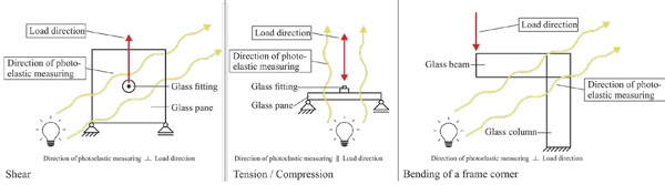
Independent form the type of joint (bonded or mechanical) three main load scenarios can be identified: shear, tension/ compression and bending, e.g. for transparent frame corners (see Fig. 6). These cases differ not only by the stress state induced in the glass, but also by the direction of photoelastic measuring. For example, in the case of shear and bending, the direction of photoelastic measuring is perpendicular to the direction of loading. For tension and compression loads the direction of photoelastic measuring is parallel to the load direction. This has to be taken into account while planning and conducting experimental investigations. Especially the second case (parallel directions) leads to a complex experimental design of the test setup.
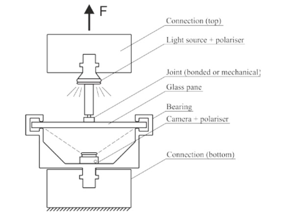
Experimental investigations are being conducted by using static testing machines in Aachen and Ilmenau while recording polarising filter images with a camera system, which is capable of determining resulting retardations and stress states in real time. As already mentioned for the load case tension/ compression the load direction and direction of photoelastic measuring are parallel, what complicates the recording of polarising filter images while bearing the specimens. It has to be ensured that the bearing does not obstruct the view on the joint and the glass area around the joint. In addition, the bearing must not have a major disruptive influence on the stress state in the glass around the joint. A concept of a test setup for such a load case is shown in Fig. 7. A glass fitting is bonded in the middle of a glass specimen, which is supported at its edges. This way, the view on the joint is obstructed by the bearing.
With the help of the presented experiments, investigations on which parameters have a photoelastic relevant influencecan be performed. The following parameters or appearances are considered relevant:
- integrated principal stress difference,
- photoelastic appearance in case of defects in the connection,
- photoelastic appearance in case of connection failure.
At present, tests are being carried out at the two institutes and results are being validated, which are soon to be published.
3.2.Superposition of results with numerical simulations
To date an exact statement concerning the two-dimensional qualitative behaviour and the quantitative stress conditions within a built-in pane, mounted using varying joining methods, is not possible. As a consequence, the valuation of mechanical stresses and loads caused by assembling or usage is currently not feasible in detail. A device which addresses this gap in research is therefore a considerable innovation.
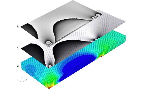
Main idea of this approach is to establish an interconnection between numeric simulation results and experimental investigations. By establishing these couplings, a methodology is developed with which quantitative statements can be assigned to the stress images. The gained results of a 3D finite element stress simulation can be used to derive a 2D virtual phase image. (Deuschle 2005, Deuschle 2006). This phase image can be compared with the experimentally determined polarising filter images and reliable conclusions about the principal stresses can be made (see. Fig. 8).
The challenge of this approach is to qualify for different connecting systems, considering the installation conditions and changes resulting from the service life of the various connecting systems, in order to derive a clear statement of the influencing factors (e.g. different tightening torque, uneven hardening, ageing and creep of the plastic elements in the connection). Moreover, the possibility of setting up a prediction model for bearable stresses has to be addressed.
The advantage of this method is the possibility to visualise and evaluate stress redistributions that may occur, for example, during the service life. The principal stresses determined experimentally with the mobile measuring device as a functional model are verified by appropriate verification methods with the aid of finite element method (FEM). Such an approach is already being worked on and numerically confirmed (Deuschle 2006, Winter 2014, Pathak 1999, Babu 2006).
The basic procedure is already possible, but there are no comprehensive models to illustrate the load-bearing behaviour of the bonded or mechanical connections as well as the characteristics of the different joint systems during installation. The procedures should be present in a program structure and be optimized and reliably available for the development of the functional pattern of the measuring instrument.
4.Summary and outlook
In order to meet the aspiration and requirements of modern architecture to further increase the transparency of buildings, the use of point-supported or bonded glass constructions offers a widespread possibility to reduce the area portion of the non-transparent attachment points to a minimum. To date, it is only possible to perform a subsequent damage analysis by visual inspection. So far, there is no method available, that is able to detect and evaluate the state of stress of a critical area in a built-in glass pane and thereby it is not yet possible to predict damage or take countermeasures beforehand.
To confirm the durability of a glass construction, the early detection of damages and therefore raise of the construction safety must be achieved. For this reason, a generally accepted non-destructive testing method, that allows to evaluate the mounting conditions has to be developed, with which is economically feasible to work with sufficient safety and accuracy in practice. This task can be solved by implementing photoelasticity with respect to the specific characteristics of mechanical and bonded mounting systems in combination with supporting numerical simulations.
At this point the research project “BiGla” comes in. The combination of hard- and software developed in this project, enables to make a qualitative assessment of transparent facade elements, panes or railing elements in a mobile as the base for extensive monitoring and prognosis concepts. The previous chapters pointed out that different kinds of influencing factors occur, depending on the used mounting system. Thereby, the challenge is to derive the stress situations for each system with respective installation conditions and significant changes during the use phase.
Possible influence factors are tightening torques deviate from the specific value, uneven hardening of adhesives, ageing, creep effects and special part behaviour of the plastic components, to name just a few. The interconnection between phase images determined in experimental investigations and calculated numeric simulation results make it possible to qualitatively assess the stress conditions during the installation and the usage phase.
Acknowledgements
This work was developed within the framework of the research project "Entwicklung eines mobilen Gerätes als Funktionsmuster – bestehend aus Hard- und Software – zur Bewertung des aktuellen In situ-Spannungszustandes im Glas – BiGla” (AiF 2017) funded by the German Federal Ministry of Economics and Energy (ZF4075115AG6 ) within the framework of the Central Innovation Program "Mittelstand" (ZIM). The authors would like to thank our project partners “Ingenieurbüro Dr. Siebert” (Munich) and “VERROTEC GmbH” (Mainz) for the good cooperation.
References
AiF ZIM Projekt: Entwicklung eines mobilen Gerätes als Funktionsmuster – bestehend aus Hard- und Software – zur Bewertung des aktuellen In situ - Spannungszustandes im Glas – BiGla, funded by the German Federal Ministry of Economics and Energy, ZF4075115AG6. (2017)
Babu, P., Ramesh, K.: Development of photoelastic fringe plotting scheme from 3D FE results. Communication in Numerical Methods in Engineering. p. 809 – 821 (2006)
Deuschle, H.M., Wittel, F.K., Kröplin, B.-H.: Simulation von Spannungsoptik im Rahmen der FEM, 17. Deutschsprachige ABAQUS-Benutzerkonferenz, Nürnberg. (2005).
Deuschle, H. M. et al.: Investigation of progressive failure in composites by combined simulated and experimental photoelasticity. In: Computational Materials Science 38(2006)1, p. 1-8. (2006).
Eliášová, M.: Advanced Design Of Glass Structures, CTU in Prague. (2015) Accessed October 2017
EOTA: ETAG 002 - Guideline For European Technical Approval For Structural Sealant Glazing Kits (SSGK), 1040 Brussels, Belgium. (1998)
Feldmann, M., Kasper, R., Di Biase, P., Schaaf, B. et al.: Flächige und zerstörungsfreie Qualitätskontrolle mittels spannungsoptischen Methoden, Glasbau 2017, Ernst und Sohn Verlag, Dresden. (2017)
GlasStress Ltd: Manual „Scatterd Light Polariscope“ (SCALP-05). Version 5.5. (2013)
Hestermann, U., Rongen, L.: Frick Knöll: Baukonstruktionslehre 1. Springer Vieweg:, Wiesbaden. 36. Auflage, S. 332 (2015)
Hildebrand, J., Werner, F.: Experimentelle Ermittlung der spannungsoptischen Konstante für Glas und Kunststoff mittels bildgebender Messmethode, Werkstoffprüfung 2010, 02. - 03. Dezember 2010, Neu-Ulm, S. 401–406. (2010)
Kuhlmann, U.: Stahlbau-Kalender 2011. Wilhelm Ernst & Sohn: Berlin. ISBN 978-3-433-02955-8, S. 638 ff. (2011)
Middleton-Pugh, J.: Echo agrees move to St. Paul’s Square, https://www.placenorthwest.co.uk/news/echo-agrees-move-to-st-pa uls-square/ (2017). Accessed January 2018
Pathak, P. M., Ramesh, K.: Validation of Finite Element Modelling Through Photoelastic Fringe Contours. Communication in Numerical Methods in Engineering. p. 229-238. (1999)
Porada, B.: Apple Patents Glass Cylinder Design. Article in archdaily. http://www.archdaily.com/tag/apple-store/ (2013). Accessed September 2016
Prautzsch, V.: Entwicklung transparent geklebter Glas-Rahmenecken und Untersuchung des Tragverhaltens, Doctoral dissertation, Technische Universität Dresden. (2015).
Schaaf, B., Di Biase, P., Feldmann, M., Schuler, C., Dix, S.: Full-surface and non-destructive quality control and evaluation by using photoelastic methods, Glass Performance Days 2017, Proceedings, Tampere, Finland. (2017)
Winter, E., Hildebrand, J.: Anwendung der spannungsoptischen Messmethode bei querkraftbeanspruchten Punkthaltern. Bauhaus-Universität Weimar, Weimar. (2014)


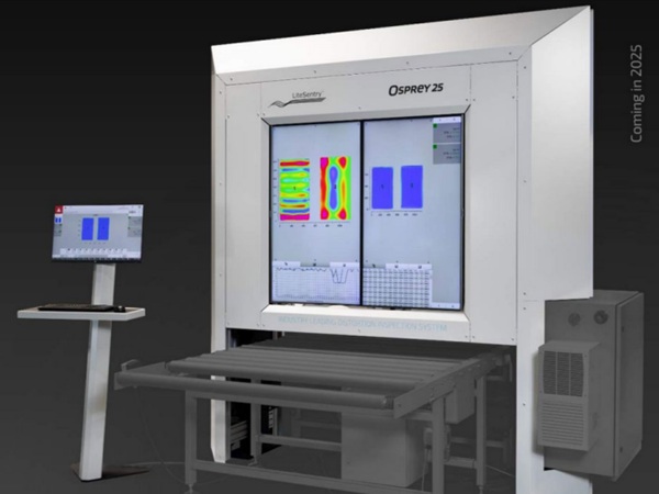


 demonstrator at Glass Technology Live during Glasstec 2024 (© Cas Maertens).")