This paper was first presented at GPD 2019 by Martien Teich, Christian Rehner and Fabian Schmid from seele GmbH.
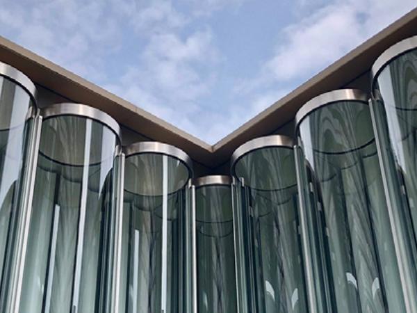
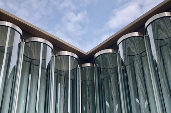
The glass tube façade consists of 307 tubes made of laminated safety glass, 238 half- and 69 full-tubes with a height of 9m and a diameter of 900mm. Aluminium profiles connect adjacent tubes with each other. Each tube has a cut duplex-stainless steel lid at top and bottom fixed with structural silicone. The façade is located in Hong Kong’s humid environment with very high hurricane wind loads.
An adopted closed cavity façade (CCF) system pressurizes the tube due to the large enclosed air volume in the cavity. seele conducted extensive testing both in Germany and Hong Kong to confirm the feasibility of the system. Half glass tubes were bent and laminated in Europe, shipped to Hong Kong and structurally bonded to form full glass tubes before installed in the high-rise building in Hong Kong.
Introduction
The closed cavity technology is a well-known and established approach for multi-layered façade systems in order to pressure-equalize the façade cavity and prevent any condensation on the glass surfaces. The closed cavity façade system increases the acoustic performance, integrates shading devices, minimizes cleaning effort, increases floor space in comparison with naturally ventilated double façade systems, and provides maximum comfort for the building tenants.
This paper shows that the CCF technology also has some great advantages for non-traditional applications. This paper first outlines general design principles for closed cavity façades. The authors discuss key aspects for special geometries and the climatic area of Hong Kong in comparison to Europe. Finally, it is shown how the volume flow of dried air through the tube influences the risk of condensation.
General Design Principles for CCF
Closed cavity façades use a pressurized air supply or a ventilation system known from the concept of pressurized multilayer ETFEfilm cushion constructions. Dried, filtered and sometimes tempered air is blown into the system to manage condensation for the cushion constructions. Mechanically driven vents or compressors, stainless steel pipework and valves are used as an air supply system. Filtration and exclusion of any contaminations of the supply air is essential in order to ensure a performing cavity condition. The designers can adjust the system performance to a more tolerant or a more effective configuration. Tightness of the elements and the pipework, an adjusted flow rate typically in the range of 3 to 40 l/h∙m³ can fulfill most project specific demands.
The CCF concept typically simplifies the glazing element in order to provide shading, light control and regulation functions as well as climate load management in one system. Realized projects are mostly high-rise buildings with office use. However, the CCF concept is also suitable for safe operation of double skin façades in challenging climatic conditions. With an appropriate design, the technology offers performance reserves and can safely control even extreme weather situations and critical climatic influences. Even extreme geometries of the glazed elements can be realized as shown in subsequent paragraphs.
The CCF design needs to configure a system with an appropriate airflow rate in order to avoid condensation under almost every environmental condition, to handle climatic and other pressure induced loads, and to minimize energy consumption. The challenge of the development is the understanding of the influences of heating and cooling on the special geometry and in the development of a defined flow rate in order to avoid congestion as well as heating.
In order to define the flow rates and the optimal inflow and outflow openings, different full-size mock-ups and numerical calculations are used. The CCF elements are generally manufactured in clean rooms. The elements are conditioned over the entire processing and supply chain until installation and commissioning in order to prevent unwanted substances entering the cavity
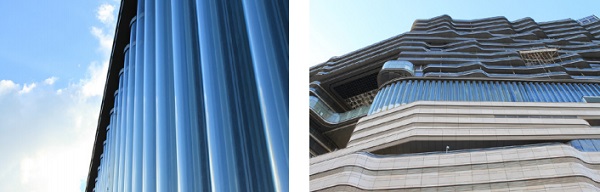
New World Centre Hong Kong
The unique glass tube façade shown in figures 1 and 2 is an attractive addition to the New World Centre in Hong Kong, a hotel and office complex in Kowloon. seele built the main façade of the New World Centre with 307 glass tubes and a special LED lighting technology between the tubes. A part of the façade is equipped with CCF technology, which is subject to special physical requirements. The whole building needs to withstand high wind loads and building movements.
The CCF system is integrated in 69 full and half tubes. Two individual CCF supply systems control the east and west façade elements separately to consider the different climatic boundary conditions. At the lower end of each tube, a small vent is integrated ensuring a pressure compensation. The mechanically driven ventilation, stainless steel pipework and valves are used for the air supply with dried, filtered and tempered air. Filtration and exclusion of any contaminations of the supply air is essential in order to ensure a performing cavity condition.
Hong Kong Climate Analysis
Knowledge and understanding of the local climatic conditions play a key role in the correct sizing of the technical equipment and the adjustment of the system when using façades and in particular CCF façades. In preparation for the project shown in Hong Kong, seele carried out basic system investigations both in Gersthofen (Germany) and Hong Kong in order to define the system parameters for a safe and long operation.
An important survey at the beginning of each project is the evaluation of local climate data in order to give a detailed assessment for the design process. Hence, the following sections describe the most important climatic differences between Gersthofen (Germany) and Hong Kong as well as their influences on the system design.
Gersthofen in southern Germany is mainly influenced by the moderate warm climate in the Alpine foothills. The climate classification according to Köppen and Geiger characterizes it as a warm temperate, always humid climate with warm summers. In comparison, Hong Kong is influenced by the temperate, warm coastal climate. In summer, Hong Kong receives significantly more rainfall than in winter.
According to the KöppenGeiger classification, Hong Kong has a warm temperate, dry winter climate with warm summers. Those climatic characteristics can also be seen in the analysis of representative weather data. The outdoor temperatures in Hong Kong are significantly higher than in southern Germany. The average annual temperature in Gersthofen is 8.5°C and in Hong Kong 22.5°C. In addition, the absolute humidity and the vapor pressures are significantly higher in Hong Kong than in southern Germany.
If the climatic conditions in the cavity adjust too slowly, rapid temperature drops or rapid vapour increases of the outside air can lead to condensation on the inside of the glass tubes as well as on the frames. For a good assessment of the functionality of CCF façades, two parameters are relevant and can be determined from representative weather data: The extent of temperature and humidity changes (rise and drop) and their probability distribution.
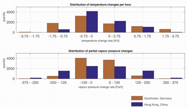
Figure 3 shows a comparison of the probability distribution of temperature rises and drops as well as changes in vapour pressures for Gersthofen and Hong Kong. Corridors from 0 to 0.75 K/h, 0.75 to 1.75 K/h and 1.75 to 3 K/h are identified to differentiate between non-critical, critical and very critical changes. In the investigation of the humidity change, the partial pressure of water vapour is categorized with pressure change rates of 0 to 125 Pa, 125 to 250 Pa and 250 to 375 Pa.
The partial pressure is another measure for the humidity change in the air, as it provides an absolute value that is independent of the prevailing temperature and gives an indication of the direction and the amount of vapour movement. Due to a partial pressure change rate, the quantity of the actual moisture input and output is evaluable independently from temperature influences.
Critical temperature increases and decreases occur more frequently in southern Germany than in Hong Kong. In addition, the comparison highlights that larger temperature drops and rises in the range of 0.75 - 3.75 K/h occur in southern Germany. Hong Kong is less critical due to the lower and less frequent temperature changes. The comparison of the partial vapour pressures and their changes show that more humid air is present in Hong Kong (as expected) and that critical drops and rises in the range of 125 - 375 Pa/h are significantly more frequent than in Germany.
The comparison leads to the conclusion that Gersthofen is more critical to temperature fluctuations and may condensate more frequently from rapidly changing weather conditions. Hong Kong is more critical due to the much greater amount of moisture in the air which, when coupled to the cavity interior, represents a condensation risk at much lower temperature changes. This leads to the recommendation that CCF façades in Hong Kong should be operated with preconditioned extract air from the air-conditioning system. This has the advantage of significantly lower amounts of moisture, which must be buffered otherwise by machine technology of the CCF air-processing unit.
System Testing
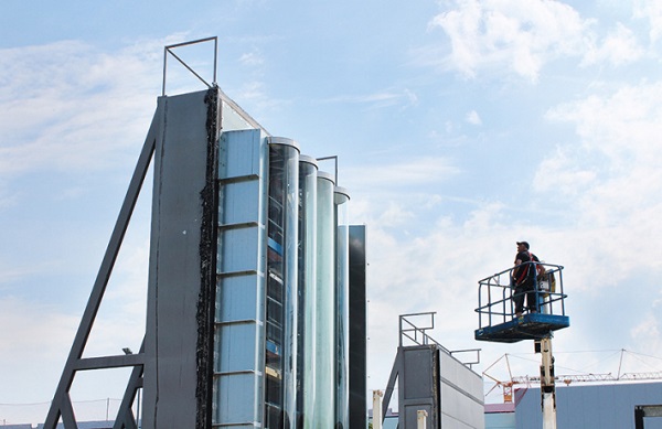
In order to define the flow rates and the optimal inflow and outflow openings, seele built different full-size mock-ups as shown in Figure 4 to investigate different system parameters by means of long-term measurements. The test engineers constantly control the system during operation to monitor conditions and detect critical changes at an early stage.
The geometry and the volume of the CCF façade influence the design of the ventilation systems. In Hong Kong, seele built two geometric types: full tubes and half tubes. The full tubes have a diameter of 900 mm, a height of 9 m and an internal volume of 5.1 m³. Due to their geometry, the half tubes have 50% of the volume of the full tubes.
In various test series, seele measured surface temperatures on the inside of both the full tubes and the half tubes.
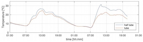
Figure 5 shows representative temperature measurements for a two-day period. The half tube shows higher absolute temperatures and faster temperature rises than the full tube. This is due to the smaller air volume and the reflective coating of the rear pane of the half tube. Half tubes tend to have lower dew points and react more quickly to system conditions.
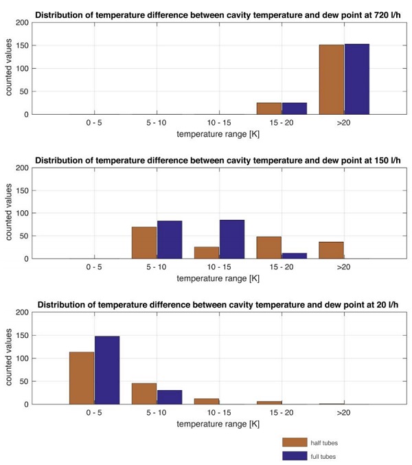
In a second step, the engineers compared the measured temperatures with the dew point temperature of the climate prevailing in the tube. Depending on the volume flow, which was set to condition the tubes with dried air at low pressures, higher or lower temperature differences were recorded between the surface temperature on the glass pane and the prevailing dew point temperature.
Figure 6 illustrates some selected results: The higher the volume flow, the lower the risk of condensation. Due to the smaller volume of the half tubes, they are better conditioned at the same air flow rate than the full tubes. This has a positive influence on the dew point of the half tubes. The difference between half and full tube is quite pronounced at the lower air flow rates of 20 l/h and 150 l/h. In the case of the full tubes, there are increasingly lower temperature differences and thus a greater possibility of condensation in comparison to the half tubes. The full tubes are a more sluggish system and should be conditioned with a higher volume flow.
The results were combined with a risk analysis for detailed planning and a suitable air flow rate in order to take into account the economic effects of building operation. The pipe diameter of the ventilation system is selected according to the design of the defined air flows in order to avoid unnecessary pressure losses. The choice of the ventilation unit depends on the pressure losses in the pipe system and the required air flow rates. Hence, an optimal air flow rate reduces the energy consumption during the lifetime of the CCF system.
Summary
This paper discusses several aspects for the design and engineering of closed cavity façade systems. As shown, the CCF technology can also be the technology of choice for modified and non-classical façade elements as the tube façade for Hong Kong’s New World Centre. The authors compare the climatic conditions in Central Europe (Germany) and Hong Kong. Although the air in Central Europe has generally lower medium temperatures and a lower humidity, the cavity temperatures in the CCF tubes change more quickly than in Hong Kong. In Hong Kong, though, the engineers have to consider the high humidity of the outside air when designing the CCF system.
CCF systems offer a good solution to avoid condensation in multi layered façade systems. Nevertheless, the optimization of the air flow rate, the reduction of energy consumption and operation costs need to be taken into account. Therefore, the system components and the integrated sensors can be used for a future optimization of the system conditions within a holistic integrated system optimization for buildings.