Authors: Jan Dirk van der Woerd, Matthias Wagner, Achim Pietzsch, Matthias Andrae & Norbert Gebbeken
Source: Glass Structures & Engineering volume 7
DOI: https://doi.org/10.1007/s40940-022-00213-w
Abstract
Explosion events represent an extraordinary action for buildings and especially for the building envelope. In addition to accidents in chemical plants or during transport of explosive substances, the threat of terrorist attacks has increased in recent years. Façade constructions, windows, and doors represent weak points in the event of an incident, through which blast waves can enter the building. Debris and fragments resulting from the failure of building components endanger people inside and outside the building. For structures that are threatened, appropriate elements with protective properties must be chosen so that an acceptable level of safety is achieved. The design and execution of a sufficiently blast-resistant building envelope is not a trivial task. In limited cases, necessary protection can be achieved by use of certified products.
Since buildings in need of protection mostly have high architectural demands, standard elements can usually not be used. Or the blast load used for certification deviates greatly from the assumed blast load for the threat scenario. There are several methods to verify the explosion resistant properties of façades, windows, doors, etc., e. g. experimental methods, numerical methods, engineering approaches and empirical methods. In this article, an introduction to explosions and their effect on the building envelope is given. Methods for verification of blast resistance are presented and critical discussed. The article presents an overview of the state of the art in practice with a focus on Germany.
Explosion: an extraordinary load case for the building envelope
Introduction
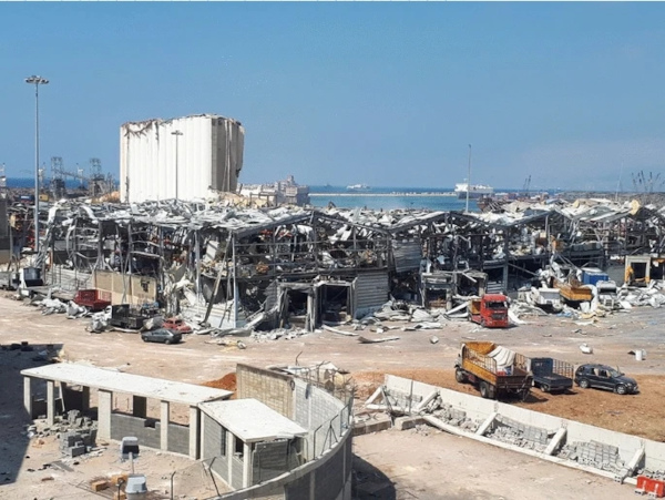
Over the last two decades, threats to buildings caused by explosions have become increasingly important for society. A major reason for this is the rising globalization of international terrorism. In addition to conventional commercial and military explosives, numerous other chemical mixtures as well as gasoline and gas pressure vessels have to be considered as threat sources. The quantities of explosives used range from a few grams in letter bombs to several tons in trucks, tankers or even ships. Another cause is possible accidents in chemical plants and storage facilities of flammable liquids, gases, and dust mixtures. In the case of accidents, the large quantities of explosive source materials result in significantly larger impact radii and a considerable damage potential up to large distances. An example for an accident is the incident at the Port of Beirut in August 2020 (Fig. 1).
Façade constructions, windows and doors represent weak points in the event of an explosion, through which blast waves may enter the building. Façade constructions, windows and doors must fulfill the following additional requirements in case of an explosive event:
- Protect people and equipment in the building from the direct effects of the blast wave,
- Avoid the formation of debris with high kinetic energy as a result of component failure,
- Preserve the room enclosing function of the building envelope,
- Preserve structural stability in case the building envelope has load-bearing functions.
Protection level and blast loads
What is a sufficient level of protection for possible scenarios and how can it be achieved? A reference to explosion resistance as a performance characteristic of elements can only be found in the product standard for windows and doors EN 14351-1, without a specific level of protection being required. No information on blast resistance is found in the product standards for façades, gates, or doors (EN 13241, EN 16034, EN 13830). The standards do not provide any support for requirements or design loads and moreover terrorists do not obey any standards. For public buildings, which might be targets of terroristic or criminal attacks Criminal Office or intelligence services offer support to analyze the risk and define protection requirements.
For non-public buildings, the determination of the threat and the selection of a level of protection is up to the building owner. For industrial facilities, possible accident scenarios can be derived with relative certainty from knowledge of the production processes or the hazardous substances present. As a condition for granting insurance coverage, insurance companies impose a certain level of protection. A source for assessing the physical effects of accidental release of hazardous material is TNO Yellow book (Committee for the Prevention of Disasters 2005). With the knowledge of potential scenarios, the blast loads acting on the building envelope can be determined, e.g. by numerical simulations.
Design methods
The design and realization of a blast-resistant building envelope is not a trivial task. In some cases, sufficient protection can be achieved by using certified building elements. Certified elements like windows and doors with proven blast resistant properties are available from various manufacturers. In most cases, buildings worthy of protection also have a representative function and thus an architecturally sophisticated design. For this purpose, recourse to standardized products is usually not possible and a new design is necessary.
The aim of this article is to provide basic information on methods for verification of blast resistance of building components. First, in the following Sect. 2 the characteristics of explosions and their effects on buildings will be discussed in more detail. A closer look on the effect of blast loads on windows is given in Sect. 3. In Sect. 4 four groups of methods for verifying the blast resistance are presented and their possibilities and limits are shown. Some advice on the definition of requirement specifications is given in Sect. 5 in order to achieve the desired level of protection. The article closes with a summary.
Characteristics of explosions
General
Definition
An explosion is a thermodynamic process in which energy is released as part of a rapid, strongly exothermic chemical reaction. It should be mentioned that besides chemical reactions there exist also physical explosions e.g. a steam boiler explosion. A chemical explosion leads to a fast and strong local increase in temperature and pressure. A blast wave is generated which propagates spherically in the surrounding media. Basically, explosions are distinguished between detonations and deflagrations (Fig. 2).
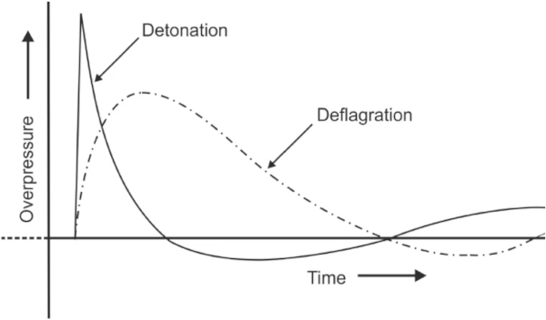
An explosion is called deflagration if the propagation velocity of the chemical conversion in the explosive is below the speed of sound. If the propagation occurs at supersonic speed, it is called a detonation. Depending on the concentration of explosive material, reaction rate and environmental conditions, all possible transitional forms from slow combustion to deflagrations and detonations are possible.
Detonations
The pressure–time history (Figs. 2 and 3) of a detonation is characterized by a sudden increase in pressure and a subsequent exponential decrease with transition to the negative pressure phase (suction phase). In common standards for blast protection of façades and glazing (e. g. EN 13123-1 2001), the detonation of explosives is used as scenario for deriving loads. Essential parameters are the peak overpressure pmax, and the maximum impulse of the blast wave. These represent the total force effect of the blast load over the exposure time.
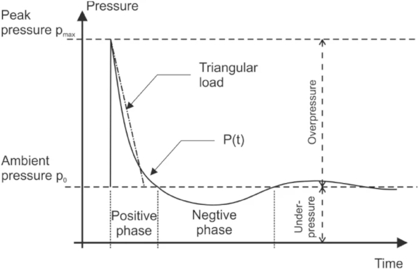
A simplified approach is to represent the pressure–time history by a triangular impulse function. The negative pressure phase of the blast wave is neglected. This is often used for design purposes. However, this assumption is appropriate for cases where only failure of the components into the interior of the building is of interest. In the case of windows and construction elements that are not allowed to be torn outward (e. g. in the case of glazing of inner courtyards or overhead glazing), the negative pressure phase must be considered, too. The negative pressure phase lasts longer than the positive phase and acts on an already pre-damaged construction. The negative pressure phase can also be favorable in limiting forward movement of ejected components or relieving the building elements. More information of the influence of the negative pressure phase can be found in Teich and Gebbeken (2010).
The magnitude of the peak-pressure and the size of the maximum impulse strongly dependent on the distance from the origin of the detonation to the building. At least for the positive phase, the parameters of the blast wave in simple cases can be determined very quickly by means of tables, diagrams or software solutions based on the work of Kingery and Bulmash (1984). The blast wave parameters differ for the cases of detonation of TNT on the surface of the ground (hemispherical) and in the air (spherical). In case of a spherical detonation shortly above the ground, the superposition of incident shock waves and reflected shock waves from the ground leads to local pressure increases and the formation of a stronger shock front. This effect is known as Mach stem (Baker 1973).
If the explosive material is not TNT a conversion into an equivalent mass of TNT is needed. By means of the ratio of the heat of detonation, an equivalent TNT mass is determined for the mass of the other explosive according to Dobratz and Crawford (1985).
Deflagrations
In the case of deflagrations, a slower increase in pressure is observed instead of the quasi-sudden increase as can be seen in Fig. 2. Deflagrations are typical for the reaction of combustible dusts, gases and mixtures of combustible liquids and air (vapor clouds). Compared to detonations, deflagrations are often characterized by lower maximum overpressures, but considerably longer positive pressure phases. This often results in impulses that are significantly higher than those of test specifications for windows and doors. In the context of risk assessments, especially for petrochemical plants, it is common practice to describe the pressure wave not only by the magnitude of the reflected overpressure at the component surface and the impulse of the reflected pressure wave, but with the course of the pressure curve.
The main parameters for determining the characteristics of a deflagration are the concentration and heat of reaction of the hazardous substance and the existing environment in which the reaction takes place. An approach for risk management in case of explosions in the chemical industry is the multi-energy method, which is described in Committee for the Prevention of Disasters (2005).
Blast wave structure interaction
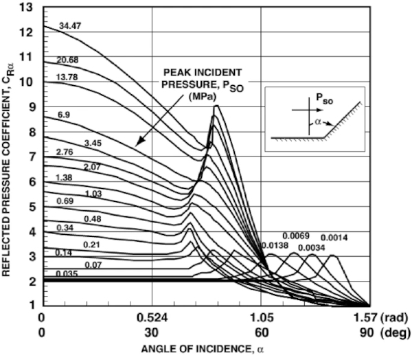
The pressure measured in an undisturbed free propagating blast wave is called incident pressure. In the case that the blast wave is interacting with an obstacle, it is reflected. The so-called reflected pressure is formed on the obstacles surface. The reflected pressure is generally higher than the incident pressure of the blast wave. The ratio of the reflected pressure to the incident pressure is called the reflection coefficient cr (Gebbeken and Döge 2006a).
In the case the blast wave hits the obstacle surface not perpendicular, the reflected pressure is also depending on the angle of impact. The reflection factors change, as can be seen in Fig. 4. Increased values caused by mach stam formation between 30° and 60° may occur at larger surfaces.
The resulting blast load becomes even more complex in case of multiple reflections due to neighboring buildings or surfaces as in urban environments. In unfavorable cases, this results in significantly higher loads than in the idealized test environment which is usually achieved with an undisturbed propagation of the blast wave. This can lead to failure of a structure that has been successfully tested for a certain quantity of explosives in a defined distance in the undisturbed free field in areas with dense building development even at significantly lower blast loading.
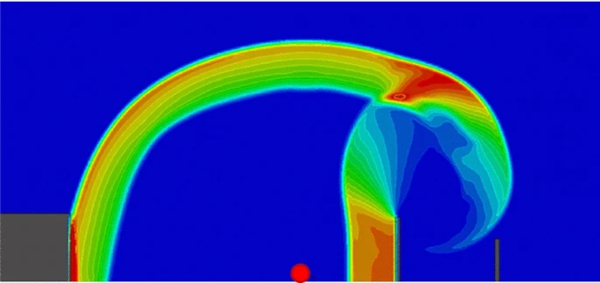
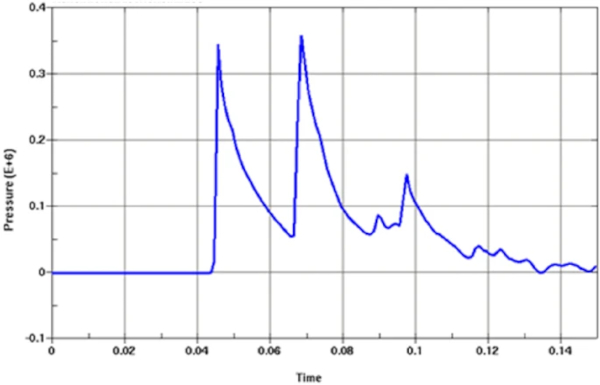
To quantify such effects, either experimental investigations on scaled models (Mayrhofer 2006) or numerical simulations of blast wave propagation are required (Fig. 5). As a result of multiple reflections from surrounding structures, extreme local fluctuations of the blast load may occur. The graph shown in Fig. 6, which was taken from the simulation of a real situation, shows the deviations from theory that can occur. Furthermore, it can be seen that the duration of the positive pressure phase increases.
Structural response to short-term loading
The ratio of duration of the positive phase (Fig. 3) of the blast load to the natural frequency of the structural component is essential for the structural response. This relationship can be highlighted with a single degree of freedom system (SDOF) subjected to a triangular impulse load. In Fig. 7 (left) the reaction of this model assuming linear elastic material behavior can be seen.
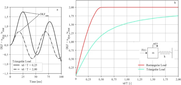
A response spectrum is used to record the dynamic system response for a wide range of action combinations and structural properties (Biggs 1964). The response spectra of a SDOF under different pulse loads are shown in Fig. 7 (right). Regardless of the modeling of the action (rectangular impulse or triangular impulse), the DLF increases with an increasing ratio between the duration of the positive pressure phase td and the natural frequency T. For a high ratio between the duration of the positive phase td to the natural frequency T (td/T ≫ 1), the dynamic response can increase to twice the value of the static response under the maximum load. A dynamic load factor (DLF) of 2.0 can be introduced here. However, for a very short positive phase, the DLF can drop to less than 0.1 at td/T < 0.025 of the static response.
Explosions inside buildings (internal explosions)
Explosions inside buildings generate significantly different, usually much higher, blast loads on the structural components than free field explosions. This effect is a result of the numerous reflecting surfaces present in the interior and of the limited possibilities for expansion of the reaction products of the explosion. In this article no further details on explosions inside buildings are discussed.
However, for building practice, it should be noted that for explosions inside buildings, the applied protection strategies are often contrary to events outside buildings. In the case of explosions outside the building, it is desired to prevent the blast wave to enter the building and to prevent debris to be propelled inside. In case of internal explosions, the goal is to ensure a pressure relief as quickly as possible to reduce the pressure inside the room.
So-called pressure relief-areas could be formed by structures that are as light as possible and have as little resistance as possible so that they fail rapidly in case of an overloading. A combination of both requirements, for external and internal explosions in one building envelope is difficult to achieve. Further information about this issue can be found in Larcher et al. (2018).
Explosion loads in standards
There is no European standard that provides information on explosion loads on buildings or load bearing structural components by explosives. Solely EN 1991-1-7:2010-12 contains special approaches for considering internal explosions as an effect on load-bearing structures due to dust explosions or natural gas explosions and explosions in road and railroad tunnels. For non-load-bearing components, such as windows, doors and shutters, there are blast loads defined in standards, e.g. EN 13124–1 (2001), EN 13123-1 (2001), EN 13123-2 (2004), EN 13124-2 (2004), EN 13541 (2012), ISO 16934 (2007), ISO 16933 (2007). These blast loads are specified for testing and classification. However, it should explicitly be noted that they do not represent any recommendation regarding the blast load for design.
Weak points of windows under blast loads
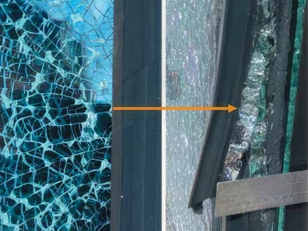
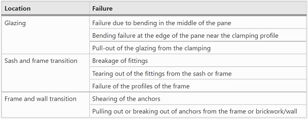
Numerous components are involved in the load bearing of explosion loads on windows. In the following, we look at a standard window made of plastic framing elements with single float glass glazing and a tilt-and-turn fitting. The window is fixed with anchors in a masonry wall (Fig. 8a). We assume an explosion in a large distance from the building so that the entire window is uniformly subjected to the blast load. For a window, the largest part of the blast load is applied to the glazing, which transfers the load circumferentially to the sash. The sash is connected to the frame via fittings, hinges, keeps and locking pins. Finally, the load is transferred from the window frame via anchors into the surrounding wall. Due to the large number of different components and transitions, even for a simple window many failure modes are possible. A summary of the most possible failure modes is listed in Table 1. A window destroyed by a blast wave after a test in a shock tube can be seen in Fig. 8b.
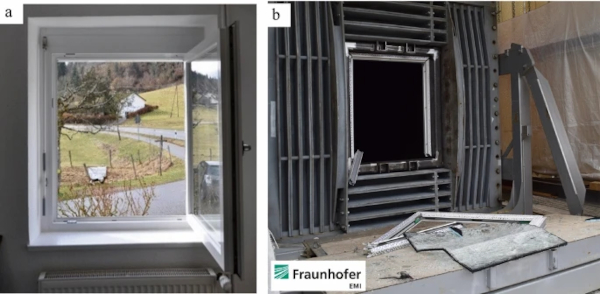
Table 1 Summary of the most possible failure modes of a simple window - Full size table
For complex façades or more elaborate structures, there may be a significantly larger number of possible weak points and failure modes. If an element of the façade fails, not only the blast wave can enter the structure, but also debris and fragments will be ejected from the construction or even the entire window. In most cases, flying debris, and not the blast wave, is the primary hazard to people in and outside the building (Bogosian and Avanessian 2004).
A strategy of strengthening windows against blast loads is to increase the dimensions of the cross-sections of its components. Thus, on the one hand, the stiffness of the components is increased, and on the other hand, the material remains in the elastic stress range even under higher blast loads. The higher material input is associated with higher costs.
However, if plastic deformation of the structural components is enabled, energy can be dissipated, which subsequently reduces the forces acting within the window and the substructure. For example, breakage of laminated safety glass dissipates a significant amount of energy. If there is no tearing of the foil interlayer or slippage of the glazing out of the clamping, there is no hazard to people and installations (Bermbach et al. 2016). To enable controlled plastic deformation and utilize load-bearing capacities lead to economical and safe blast-resistant designs.
Especially for large façades with hundreds of m2 the consideration of these aspects leads to large savings without reduction of the protection level compared to the strengthening strategy by extensive increase of cross-sections. Information on concepts for explosion resistant design of façades can be found in Gebbeken (2006), Gebbeken et al. (2010) and Wagner (2009). Andrae et al. (2019) describe a series of free field tests on buildings in full-scale made of masonry, reinforced concrete and steel. To investigate the resistance of the façade and the entire building and to evaluate the efficiency of hardening measures, one half of each building was constructed in conventional manner and the other half with hardening measures.
Since we are dealing with transient fast changing loads, the dynamic properties of structural components have a large impact on the dynamic response. The influence of dynamics makes it difficult to assess the blast resistance of a window. For normal quasi static loads like wind or snow the load duration from 3 s up to several days is long compared to blast loads. In this case the structural resistance can be estimated and interpolated from known results. In static cases the influence of changes of size of structural elements and load can be predicted by use of formulas or table works. This is only possible to a very limited extend for structures under blast loading and an individual analysis is necessary.
Methods to verify blast resistance and standards
Overview
Blast resistance is not a mandatory requirement in national building regulations such as stability, fire safety, noise protection or thermal insulation (Bauministerkonferenz 2022). The underlying threat scenario and desired protection level are determined by the building owner or user. In some cases support is provided by security and intelligence services. Threat scenarios have to be developed and analyzed. A reasonable protection level has to be chosen and blast loads have to be defined.
The task is, to analyze whether the selected structural elements meet the requirements for the blast resistance. The following four classes of methods are common to verify blast resistance:
- Experimental methods,
- Numerical methods,
- Empirical methods and
- Engineering approaches.
Since there are no specifications, the choice of a method depends on limits and accuracy of the method, the acceptance of the owner or the authorities. Furthermore, available experimental capabilities and economic constraints are also restricting points. In the following sections, various methods will be described in more detail and evaluated regarding their informative value for the achievable level of protection.
Experimental methods
Standards
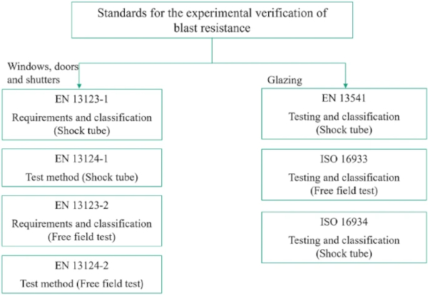
Due to the lack of sufficiently validated calculation methods for determining the resistance of façades, windows and doors, in particular experimental methods have been further developed in recent decades. Existing national standards (Fig. 9) describe two different test methods for the experimental verification of blast resistance. Complete windows, doors, shutters and construction components are tested either in a shock tube or in a free field test. Individual glazings are tested only in the shock tube. According to ISO 16933 (2007), glazings can also be tested in a free field test.
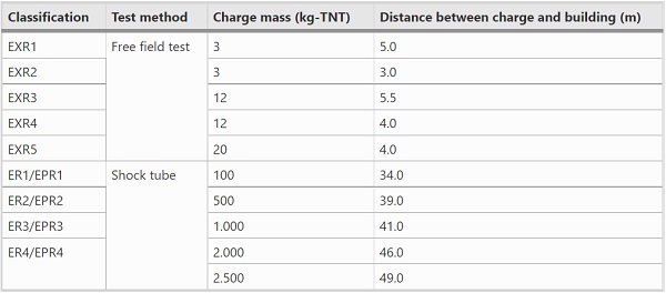
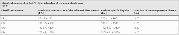
The execution of a verification test in a shock tube or a free field arena has a considerable influence on the scenarios, which can be generated. A list of scenarios corresponding to classification codes of EN 13123-1 (EPRx) (2001), EN 13123-2 (ERXx) (2004) and EN 13541 (ERx) (2012) is shown in Table 2.
Table 2 Equivalent charge mass and distances between charge and building for shock tube tests and free field tests according to (EN 13123-12001), (EN 2004) and (EN 2012) - Full size table
However, in reality the blast load not only depends on the size of the charge and the distance to the structure. The height of the charge above the ground, the shape of the charge, the position of the detonator within the charge as well as the packaging of the explosive have a large impact on the resulting blast wave. These uncertainties have to be considered when comparing the experimental results and evaluating the desired protection level. In the following the free field and shock tube tests for windows according to EN 13123 (2001, 2004), EN 13541 (2012) and EN 13124 (2001, 2004) are discussed.
Free field test
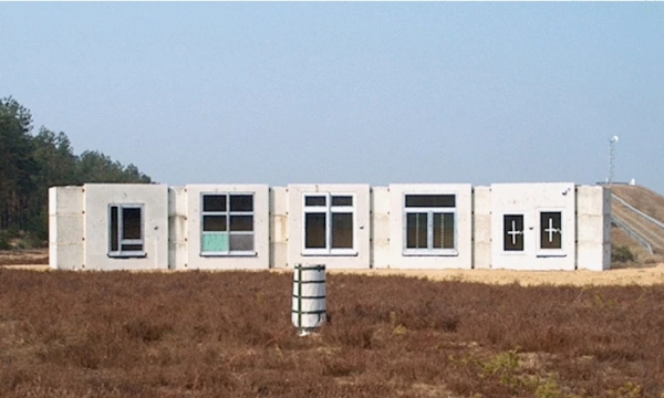
Free field tests offer some significant advantages and are therefore an essential part of the development and certification of explosion resistant façades. Structures with arbitrary dimensions can be tested in the actual size used. Figure 10 shows a such a full-scale test. To realize the desired blast loads sufficiently large test areas are needed.
Several structures can be tested simultaneously in a free field test arena using only one explosion. In addition, by varying the distance from the charge, it is possible to generate different levels of blast load. However, the setup and instrumentation of such tests are very complex and costly. In addition, considerable safety distances must be ensured, especially for tests with larger charges. Therefore it becomes challenging to conduct an free field test with more than 100 kg TNT equivalent in Germany nowadays. Another issue is the repeatability of an experiment. The blast load from the same charge and distance varies depending on many additional influences.
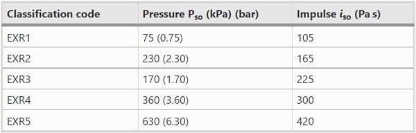
The EN 13123-2 specifies requirements and classifications for free field tests. The corresponding test method is described in EN 13124-2. As can be seen from Table 2, free field tests according to EN 13124-2 are representative for events of small charge masses at small distances between the charge and the building. The scenarios correspond, for example, to the threat scenario of a backpack bomb. At such small distances the blast load is not uniform and varies across the attacked surface. Controlled measurement of the actual blast load on the surface of the specimen is difficult, costly, and subject to inaccuracy. Comparability of the blast load is therefore controlled by charge size and distance. For a successful test it must be confirmed that full order detonation takes place. The incident (side-on) blast parameters are at least measured at the relevant classification stand-off distance. It is assumed that full order detonation has occurred if the incident peak pressure (Pso) and the positive specific incident impulse (iso) exceed the values in Table 3 as specified in EN 13124-2 (2004).
Table 3 Minimum value of incident peak overpressure Pso and incident impulse iso to confirm full order detonation according to EN 13124-2 (2004) - Full size table
The test is successfully passed if there is no perforation of or opening in the test specimen or between the test specimen frame and the test specimen support, through which a blunt 10 mm rigid bar can gently pass. Also, no parts of the frame or hardware (splinter, fragments) may be ejected from the protected side. After the test, security closures or locking mechanisms secured before the test must remain secure. The test is also considered successful if the opening mechanisms are no longer operable. In addition, the reported test results are supplemented by the suffix "S" or "NS", depending on the presence (“S”) or absence (“NS”) of splinters ejected from the protected side of the test specimen.
Shock tube
The second possibility of performing tests are shock tube tests. In a shock tube uniform shock waves are generated in long, closed tubes and propagate one-dimensionally along the tube axis. Due to the closed system, extreme safety distances like in free field testing are not required. In addition, the shock wave can be reproduced more accurately than in a free field test.
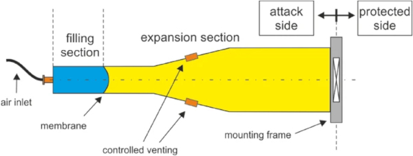
Shock tubes can be driven by compressed air or explosives. An exemplary longitudinal section of an air-driven shock tube is shown in Fig. 11. It is designed as a two-chamber system consisting of a filling section and an expansion section. Both chambers are separated from each other by a membrane until the start of the test. The characteristics of the generated shock wave can be influenced by varying the volume and pressure in the filling section. A large range of scenarios between car bombs with several kg of TNT up to nuclear detonations can be simulated. The targeted abrupt, fragment-less destruction of the membrane causes the air volume of the high-pressure filling section to escape into the expansion section. A planar shock front is formed with a characteristic pressure–time curve shown in Fig. 3, which finally hits the specimen at the end of the shock tube. The side exposed to the shock wave is called attack side and the side at the rear protected side. In case of explosion-driven shock tubes, explosives provide the driving energy for the shock wave.
A wide range of measurement methods can be applied during the test. In addition to mandatory pressure gauges and high-speed video recording, the deflection of the specimen during the test can be captured with laser measurement. Other more sophisticated methods such as the use of acoustic sensors (Woerd et al. 2020) or tracking of debris by use of high-speed photogrammetry (Schneider et al. 2019) are being investigated. It must be noted, that when planning the use of measurement devices, the possibility of their destruction by failure of the specimen has to be considered.
An unfavorable fact of shock tubes is, that inside the closed tube multiple reflections of the blast wave can occur. In order to demonstrate this effect the pressure–time history and the impulse-time history of a test in an air-driven shock-tube is shown in Fig. 12. According to the reflected peak over-pressure and reflected maximum impulse in the primary shockfront the blast wave can be classified as EPR1/ER1 (according to Tables 4 and 5). The blast wave is reflected multiple times at the mounting frame and the closed end of the tube. After 80 ms the specimen is hit by a reflected wave. The maximum impulse of this second blast wave is almost at the same level, than the first one.
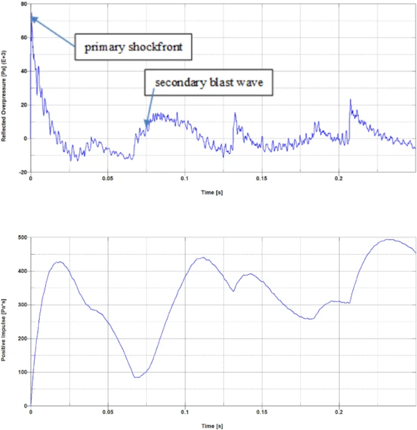
Table 4 Blast load parameters and classification according to EN 13123-1 (2001) - Full size table
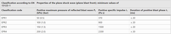
Table 5 Blast load parameters and classification according to EN 13541 (2012) - Full size table
The multiple loading of the specimen by several blast waves is not desired since the classification is solely related to the first blast wave. Nevertheless, the state of the window after the test is decisive for classification. This leads to the question of what can be done if protective elements withstand the first blast wave, but fail due to successive loading by additional waves acting on predamaged structures? The use of high-speed video can clarify the situation, but still the correct assessment is questionable. A protective element might also have failed solely by the first blast wave, during continuous decaying oscillations at a moment after the arrival of the second or third wave. A solution avoiding multiple reflections is the installation of a controlled venting (cf. Fig. 11), as realized in Gan et al. (2020).
In the following the common test standards in Germany are briefly described. The EN 13123-1 specifies the requirements that windows, doors and shutters as well as façade elements must meet to achieve classification when tested according to EN 13124-1. Based on the results, the protective construction is classified into one of four classes (Table 4). The achievement of a particular class implies that all lower classes are also achieved.
The EN 13541 (2012) specifies requirements and test methods for the classification of blast-resistant security glazing with a shock tube. A series of three identical specimen is tested with a separate test each for classification. The specimens have dimensions of 1100 mm × 900 mm and well defined support conditions. If all three specimens in the sample meet the performance requirements, the glazing may be assigned to the corresponding class (Table 5).
The requirements are met if none of the three specimens has any holes and there is no opening between the clamping frame and the edges of the specimen. Results can be further notated with the addition of an "S" or "NS". Suffix "NS", no splintering, means that no fragmentation occurred of the last pane rear face of the test piece, suffix "S", splintering, the last pane rear face (opposite to the blast loaded side of the specimen) is fragmented, is broken or splinters of the glass are detached from the test piece. This distinction is stricter than EN 13124, that allows breakage of the last pane to obtain “NS”, of course if no splinters occur.
The classification is only valid for the tested glazing sizes of about one square meter. According to the standard, a transfer to other sizes is not excluded. In this regard, it is stated: "Based on theoretical considerations and/or experimental work, the results can be used for estimating the explosion-pressure-resistance of other glass sizes."
Limitations of testing in practice
Experimental testing of structural components is generally relatively cost-intensive and usually the test specimens are damaged or destroyed. The execution of shock tube tests tends to be more cost-effective than free field tests, but they are limited to relatively small test object sizes. In addition, each individual test only provides information on one load curve and the structural behavior under exactly this blast load. Statements about the ultimate blast resistance of the individual structural components and thus conclusions about the behavior under non-tested blast loads are only possible to a limited extent. Apart from that, statistical influences such as scatters in the material properties and manufacturing tolerances might be insufficient recorded since only a rather limited number of tests are performed. Larger test series do not make sense for the manufacturer if only classification is aimed at and financial constraints have to be obeyed.
Detonations of explosives are subject to extremely variable and difficult-to-determine action variables that encounter an extreme variety of constructions. Structural optimizations can therefore only rarely be realized by means of experimental methods.
The representation of realistic suction phases is only possible to a limited extent in shock tubes, which means that additional considerations may be necessary for structures that are not supposed to fail in the direction of the attack side.
If we look at the criteria for classification according to the national standards, we can see that they are likely more based on the test technique rather than on the potential hazard. Two examples:
- It is unclear what potential hazard is investigated when the size of perforations in a window is checked with a 10 mm rod.
- Regarding the presence of only one small splinter leads to the addition of a "S", even the splinter poses no danger to a person at the protected side. Here, the difference in the level of protection to a “NS” classified product is not recognizable. The presence of splinters can easily be checked within the evaluation of the test, but its informative value for the level of protection is limited.
A slightly more reasonable assessment of the protection and hazard level is achieved by use of a witness area with a witness panel as described in the GSA test method (GSA 2003) or the ISO standards (ISO 16933 2007; ISO 16934 2007).
Remarks on test certificates
In blast resistant buildings, often certificate-based products for blast resistant façades and window constructions are used. The certificates are issued after a successful test and prove the blast resistance of a product. For practical reasons, it is often not possible to perform a test for each type of window, door or gate used in a building and for the defined blast load. At the same time, individual sizes, dimensions, and requirements result in individual adaptations for almost every component, leading to deviations from already tested systems.
The primary goal of the standards is to uniformly classify protective elements and to make them comparable to each other. Nevertheless, some examples where the use of certified products should be critically reviewed:
- In most cases the real installation situation cannot be predicted or represented exactly in the test. An example would be a test and classification of the blast resistance of a window with a free field test. If the structure was classified as EXR3, this may mean that the structure was successfully tested with an explosive charge of mass 12 kg at a distance of 5.5 m. It is not guaranteed that an installed window in a different environment (e.g. installation height, anchoring conditions, wave reflection on additional surfaces) will successfully resist the same explosive charge at the same distance.
- Changing boundary conditions or statistical influences e.g. by glazing scratches are not covered by the test standards.
- Test results cannot be easily transferred to other dimensions. However, no regulations exist to the extent of deviations and changes from the tested design, that is acceptable without requiring new tests. For example, larger dimensions for windows commonly lead to higher stress in the material. The same applies to other profile combinations, lock types, modified load-bearing systems, and installation conditions.
- The anchoring e.g. in walls is usually not tested with all relevant details in the test procedure. For example, anchoring blast resisting windows in masonry walls instead of concrete may lead to insufficient resistance against the blast load.
A glazing tested according to EN 15341 says nothing about the achievable level of protection of an entire construction. In the test only the glazing is tested. The behavior of the glazing in connection with a frame and the substructure is not tested and not included within the certificate. Furthermore, in the standard the glazing support conditions are specified far away from support details for real applications.
Many manufacturers of façade elements have their products tested by an institute but forego certification. They manufacture the protective elements on their own responsibility and without monitoring the production quality by independent third parties. In some cases, blast-resistant protective elements are also built by licensees who do not have a comprehensive insight into the tests themselves. However, experience shows that designs with serious deviations from actually tested systems are installed time and again.
Usually only the test certificates are used to prove the performance of an element. The certificates contain the classification load, the structure dimensions, the profile series and the glass sizes. More information such as the actual measured pressure–time history, number, position and type of fittings and anchors, material qualities, glass thicknesses and many other details according to the test standards are included within the test reports. Giving insight to the report is at the decision of the manufacturer. Although there is already a lot of information within the reports, that help to better understand the result and the performance of the element, more information would be often desirable, like the pressure–time history over a longer period including information about multiple blast wave reflections or high-speed recordings.
Numerical methods
For a realistic computational analysis, combined calculation procedures have been developed in recent years that are based on the use of complex nonlinear simulation methods. Within the framework of these procedures, numerical models, which are calibrated by the recalculations of available test results, are transferred to new and modified constructions or blast loads with the goal to evaluate the protection level of these constructions.
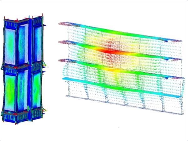
Such simulations of a whole construction require a complex computational model with detailed representation of all individual parts, including all geometric and physical nonlinearities. Approaches to this can be found in Müller and Wagner (2006), Pietzsch and Wagner (2013), and Rutner et al. (2008). In (Larcher and Solomos 2012; Hooper et al. 2012) different experiments on laminated glass are described and simulated. An overview of methods for numerical simulation of blast loaded laminated glass is presented in ERNCIP (2014). Such methods contribute significantly to a better understanding of the complex interactions within façade structures under highly dynamic loads and are more and more used successfully in the development and optimization of high-performance protection concepts (Fig. 13).
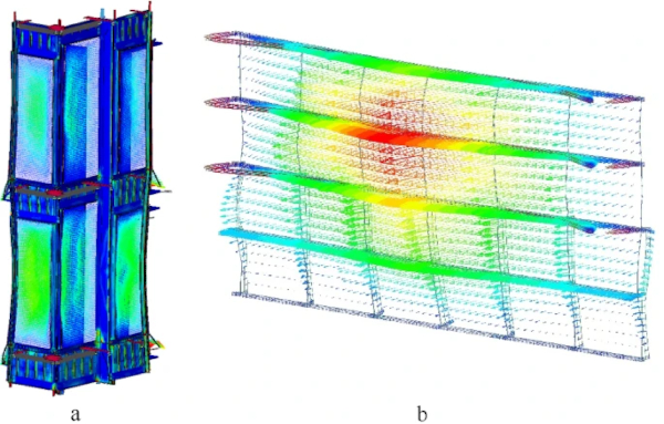
As can be seen from the shown examples, finite element simulation allows to perform qualified security analyses for unusual load cases, even for unique structures with high architectural demands. The effects of a scenario can be analyzed and countermeasures can be integrated into planning. However, there are no national standards or regulations for numerical simulations of blast loaded windows and doors. Even though numerical simulations are very powerful, the creation of detailed models requires a high level of effort and expertise.
Engineering approaches
General
There are no European standards or regulations for verifications with engineering approaches. However, American standards and regulations are available (Technical Manual TM 5-855-1 1987; Technical Manual 5-1300 1990; Manual EM 1110-345-415 1957). By means of engineering approaches, usually, single parts of a construction are individually analyzed. Such methods are mostly based on a so-called single degree of freedom system (SDOF) (Biggs 1964). They offer the possibility to design simple constructions robustly and safely with sufficiently conservative assumptions.
The mechanical behavior is described by resistance-deformation relationships, whereby elastic, plastic and damaging states can be recorded. Depending on the complexity of these functions, different static systems, support conditions and failure states can also be included. The maximum deformation states are used as criteria for assessing the degree of damage to components. Depending on the design and the safety to be achieved, maximum support rotations or maximum plastic deformations can be set as limit values. Values for these limits can be determined experimentally (Fischer et al. 2021), by numerical simulations including all failure mechanisms or for simple systems due to analytical considerations.
In the absence of tools suitable for the consideration of complete façades under explosion loading, a separate consideration of glass and substructure is often carried out for simple constructions, such as regular mullion-transom façades. In order to satisfy the separation of glass and substructure, very restrictive deformation limits must be observed by the substructure. In other words, the substructure must not deform too much to ensure that the glazing does not detach from the supporting structure. This leads to very massive substructures. However, it has been shown that modern façades offer significantly higher safety when the substructure and / or the mounting can deform plastically. Even large deformations can be accepted under the condition that the load path is not destroyed. In the following the use of P–I-diagrams and equivalent static loads are introduced.
P–I-diagrams
From various single degree of freedom systems with numerous load combinations of peak pressures and maximum impulses, so-called P–I diagrams can be generated. P–I diagrams can also be created based on several experiments or numerical simulations. Numerically determined P–I diagrams for windows are presented in Zhang et al. (2013).
They indicate the degree of damage (destruction characteristics) for load combinations and thus allow a good estimation of the damage caused by variable blast loads. Destruction curves in the P–I regime are determined for different degrees of damage to enable an estimation of the extent of destruction. More information on P–I-diagrams can be found in Krauthammer (2008).
An example of a P–I-diagram for a wall can be seen in Fig. 14. The impulse is shown on the abscissa and the pressure on the ordinate. The diagram is in double logarithmic scale for both values. The curves are iso-damage curves representing pressure and impulse combinations with identical damage. Here, the lower curve represents the elastic limit of the wall and the higher curve the experimentally determined complete destruction. Within the example shown in Fig. 14 there are three ranges, denoted by the numbers 0, 1 and 2, which define the degree of damage of the structural element, here the wall:
- Range 0: the structural element deforms within its elastic limit and suffers no damage,
- Range 1: the structural element suffers permanent damage. The severity of damage increases from the line of elastic limit in the direction of the line of total destruction,
- Range 2: the structural element fails completely to total destruction.
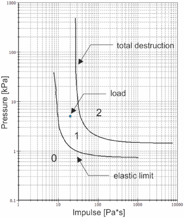
The diagram is applied by entering the peak overpressure and the impulse of a blast load into the diagram. Depending on the location of the intersection point the behavior and potential damage of the structural element can be estimated.
Static equivalent loads
In order to avoid dynamic calculations static equivalent loads can be applied. The so-called dynamic load factor can be determined that is used to increase the static load. The dynamic load factors can be determined from tests, inverse checks or by means of systems with one or more degrees of freedom. Based on the measured or calculated deflection, a equivalent load is determined, that produces the same deflection as the blast load in the test. With this equivalent load a usual design is possible. Since a static equivalent load in a nonlinear system with a large number of contacts, possible failure modes, nonlinear material behavior, etc. is only valid for exactly one system and load combination, the design can lead to an uncertain result in case of changes in layout and size. A static equivalent load, which is then really on the safe side, often leads to "over-dimensioning". The use of static equivalent loads is not recommended for windows and facades (Gebbeken and Döge 2006b).
Empirical methods
Empirical formulae can be derived from physical tests, numerical calculations, experience or a combination of them. With a set of (incomplete) data a trend curve can be extrapolated. Empirical formulae are not based on physics or theory. They simply transform a set of single data into a mathematical formula. Empirical formulae can be used as input for engineering approaches. They have to be applied very carefully because the sources of the formulae are mostly unknown. They can be used for pre-design as well as for verification and validation of results.
Requirement specifications and sources of error
In practice, it can sometimes be observed that values from test standards, which were developed in connection with real explosive attacks (detonations), are used for proving the explosion resistance in connection with deflagration. It happens surprisingly often that only the maximum overpressures from the tender are compared with the tested values. With this the suitability of the product is proven. This procedure does not take into account the impulse, which is decisive for the severity of a blast wave. Despite lower peak overpressure, deflagrations usually have a significantly longer duration of the positive pressure phase than detonations. The acting impulse can thus be many times higher than in case of a detonation.
Thus, for example, a design of class EPR1, taking into account only the overpressure, may seem to be sufficient, but this does not apply to the impulse. Here it quickly comes to the case that even protective measures that meet the high requirements of EPR4 are not sufficient as protective measures in the event of deflagrations. Another source of error is the specification of the type of peak pressure, which is often unclear. It must be specified whether it is the peak overpressure of the incident or the reflected pressure wave. To avoid errors, all information on the assumed loading must be clearly defined and communicated to all involved parties.
Required information are:
- peak overpressure,
- impulse of the positive pressure phase,
- duration of the positive pressure phase,
- the shape of the blast wave—pressure–time history can sometimes differ significantly,
- specification, whether it is the incident (side-on) overpressure or the reflected overpressure,
- analogous specifications for a suction phase, if this is of importance and
- acceptable levels of damage/performance requirements.
Here a conflict often arises between the client's interest in keeping the exact thread szenario details as secret as possible and the construction firm's need for information, which they have to include in the construction, literally without knowing them. This conflict often leads to misunderstandings resulting in suboptimal or even unsafe constructions.
Summary and conclusiones
Explosions are an exceptional hazard to buildings and especially for the building envelope construction. For structures at risk, protective measures are necessary to protect the building interior and in particular people from blast and debris. To minimize the risk to people and installations, façades, windows, doors and other closures of the building envelope should be designed to withstand a given blast wave. In order to prove the blast resistance of the structural elements of the building envelope the knowledge of the characteristics of explosions and about the behavior of the structural elements under blast load is mandatory. In this article, an introduction about the weak points of façades and windows under blast load and selected topics of explosions and their impact on buildings was given.
To prove the blast resistance of structural building elements four different classes of verification methods were presented. The methods can be divided into experimental, numerical, empirical, and engineering approaches. An introduction to these methods, their limitations, and possibilities as well as underlying standards and regulations was given. Some issues about the use of test certificates and test criteria of experimental methods have been reviewed. Advice has been given on formulation of requirement specifications and to avoid sources of error. Common to all methods is the need for a great deal of experience and knowledge in applying them and interpreting the results for achieving a satisfying level of protection. It remains to be said, that blast protection is a topic that has to be included in an early stage into the design of constructions, which is called the security-by-design approach.
References
Funding
Open Access funding enabled and organized by Projekt DEAL.
Author information
Authors and Affiliations
MJG Ingenieur-GmbH, Munich, Germany - Jan Dirk van der Woerd, Matthias Wagner, Achim Pietzsch & Norbert Gebbeken
RISK Research Center, University of the Bundeswehr Munich, Neubiberg, Germany - Jan Dirk van der Woerd, Matthias Andrae & Norbert Gebbeken
Corresponding author
Correspondence to Jan Dirk van der Woerd.
Ethics declarations
Conflict of interest
On behalf of all authors, the corresponding author states that there is no conflict of interest. The work is based on the experience of the authors from practice and scientific research. The authors did not receive support from any organization for the submitted work. The authors have no relevant financial or non-financial interests to disclose.