Source:
Challenging Glass 7
Conference on Architectural and Structural Applications of Glass
Belis, Bos & Louter (Eds.), Ghent University, September 2020.
Copyright © with the authors. All rights reserved.
ISBN 978-94-6366-296-3, https://doi.org/10.7480/cgc.7.4493
Authors:
Koos Fritzsche - Octatube
Wouter van der Sluis - Octatube
Erik Smits - ZJA Zwarts & Jansma Architects
Jack Bakker - ZJA Zwarts & Jansma Architects
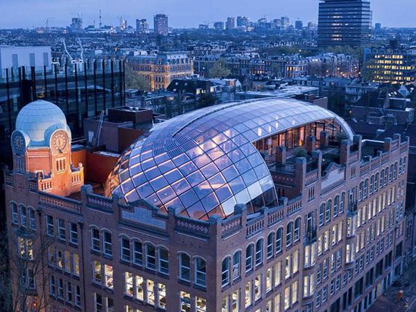
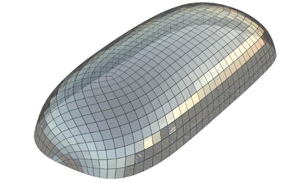
The former Diamond-exchange building in Amsterdam, now called Capital C, is restored to its former glory and currently undergoing a major renovation. This listed building has been returned to its original design and topped with a spatial gridshell roof structure of glass and steel, designed by renowned architect office ZJA Zwarts & Jansma Architects. This paper focuses on the geometric optimization of the free-form gridshell towards planar quad glass units.
The final shape of the gridshell is determined by a parametric computer model. With a by ZJA in-house written program, the boundary conditions were defined, where after the software searches the ideal shape. In the case of Capital C, the ideal shape was a geometrical free-form shape but with planar or minimal curved quadrilateral glass. This to represent the faceted aesthetics of the diamond, representing the building’s heritage. In addition to the look, optimizing to planar glass panes also increased the feasibility and cost-efficiency of the design. During this process Octatube, as a specialist Design and Build contractor, was approached and challenged to realize this innovative and complex design.
In principle the gridshell has one repetitive structural steel connection. However due to its shape every connection is unique and itself composed of many unique parts. In the final design, approximately 1000 different steel elements and 200 different glass units are applied. With a traditional design method, where all elements are modelled one by one, a minor change to the geometric shape of the shell would lead to a large amount of labour. A time-consuming and error-prone job. Therefore the design is automated, by means of an in-house developed parametric tool by Octatube, which converts the complex basic geometry into a FEM-model and detailed production model.
The applied methods of parametric design and engineering allowed the team to not only optimize the glass-design until late in the engineering phase, incorporating a file-to-factory workflow, it also allowed for fast and very precise pre-fabrication. Not unimportant when installing a free-form glass and steel gridshell on top of a listed building in the heart of Amsterdam.
1. Background
As a building and as an institution the Diamond Exchange, built in 1911 after a design by Gerrit van Arkel, crowned the heyday that counted as a second Golden Age for the city of Amsterdam: the economic boom following the 1880s, that restored the city as a metropolis for industry and trade.
However, at the beginning of the 21st century, the building was in a poor state. After several additions, a fire and various renovations much of the original charisma was gone (Fig. 1)
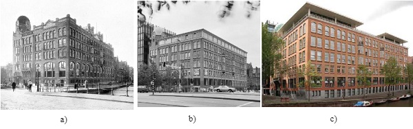
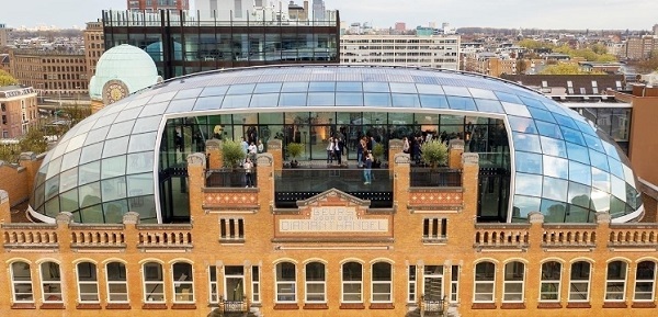
A thorough renovation was called for and ZJA Zwarts & Jansma Architects were asked to produce the design with three objectives: First of all,to restore the original qualities of the Diamond Exchange in its full glory. Secondly to adapt the interior for use as a modern, flexible office environment and thirdly to build a contemporary addition open to the public. That addition, an event space and terrace on the seventh floor, under an oblong dome, is the subject of this paper (Fig. 2).
Since many of the constraints put on the dome (available floor area, materials used etc.) were given from the onset, a thorough, methodical search through the available design space could be performed. The structure of paragraphs 2-4 more or less faithfully reflect the chronology of that search.
After the development of the principle design, Octatube was challenged to further develop the technical detailed design, optimization of steel structure detailing and the production methodology of the gridshell. The steps taken towards the final manufacture and installation of the rooftop build-up are described in paragraph 5-9.
2. Choice of glazing system
During the whole design process, the glass geometry has been the leading consideration. It was assumed that a suitable steel structure could always be found for any sensible glass geometry.
Also, in a very early stage, a triangulated geometry was ruled out for aesthetic reasons. The overall geometry would consist of quads, with possibly some triangular panels in special places.
Besides the rectangular overall geometry of the glass, the way this glass would geometrically follow the curved dome was an essential boundary condition for the further design. Four options, each with their own pros and cons, were considered:
- Double curved glass;
- Single curved of constant radius;
- Planar quad panels, with offsets between edges of adjacent panels;
- Planar quads with flush edges.
2.1. Double curved
Clearly double curved glazing comes closest to approaching a free-form, smooth oblong dome. However, it is also by far the most expensive option, more so because the geometry allows for little repetition in the shape of individual panels, so reuse of moulds is not possible. It was therefore ruled out on cost grounds.
2.2.Single curved
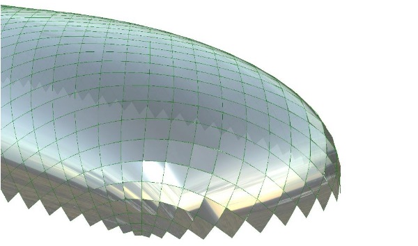
The principle of the single curved option is that each panel is assumed to be cylindrical, with constant curvature. For each individual panel the bending radius and the bending axis are decided by measuring the curvature of the underlying, smooth reference surface at the panel centre. The radius is then set to the principle curvature direction with the smallest radius, the bending axis aligns with the other principle curvature direction.
This works well for the middle part of the dome which is more or less cylindrical: bending axis and radii of adjacent panels match up, leaving no gaps between panels. The ends of the dome however are more or less spherical. Here the principle curvature direction of adjacent panels, and therefore the edges of the panels, will in general not align. This difference in edge shape can be taken up by adding framing with sufficient depth, that hides this discrepancy, but that would clash with the desire to have an uninterrupted exterior.
Moreover, since the bending axis differ from one panel to the next, reflections in the glass tend to emphasize the shortcomings (see Fig. 3). It was therefore not our favoured option.
2.3. Planar with edge offsets
Panels are laid out next to each other, without any need for the edges to align. While three planes always intersect in one point, but four planes generally do not. This results in gaps between panels, that can be filled with some form of framing. The result is a ‘scaled’ appearance (fig. 4).
Geometrically this is the easiest method to implement, since hardly any constraints are placed on the orientation of the glass. It does however add complicated detailing of the framing and a very specific aesthetic. It was rejected on those grounds.
2.4. Planar with flush edges
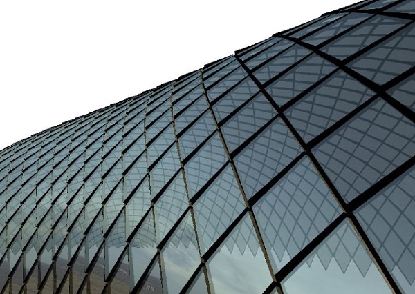
In a way this option is the opposite of the previous. It is harder to develop the proper geometry because of strict constraints: panels must not only be planar, but all panels surrounding a vertex have to intersect in one vertex as well. And where the former option needs intricate detailing, for this one a simple seam between the flush edges of panels will suffice.
Paradoxically, even though a solution with planar panels seems, at least in principle, less smooth than one with single curved glass, the overall appearance of the planar panels looks like a better approximation of the smooth reference geometry (compare Figs. 3 and 5).
3. Topology and geometry
For its aesthetic qualities, lower cost and simplicity of the detailing, planar glass panels with flush edges was our preferred option. This choice for the local glass geometry means that the final design will be an approximation of the smooth, idealized version of the reference shape we set out to achieve. The challenge was to match the topology and geometry of the design as closely as possible.
Looking at the glass surface as a quadrilateral mesh, it can be further broken down to edges and vertices, the elements wherein the curvature of the shape is concentrated. For the edges following this geometry is not a problem: two adjacent faces meet at an angle and intersect in a straight line, giving the glass panes straight edges. Which is exactly what we want.
The problem arises with the vertices. The majority of the mesh vertices will have valence 4, meaning that at each vertex 4 planes will meet. Now, whereas 3 (non-parallel) planes always intersect in one single vertex, 4 planes generally do not. We can fix this problem in one spot by changing the geometry slightly, but it then tends to pop up at some other vertex. It is a problem that cannot be solved locally. It has to be done globally, moving every vertex in the mesh in small increments, trying to conform to all the constraints at once.
3.1. Topology drives geometry
The topology of a mesh is defined by the connectivity of its vertices and faces, regardless of dimensions. It determines the number of faces that meet at the vertices.
Not every mesh topology lends itself equally well to be optimized towards the desired shape. For the mesh to have a good chance to satisfy all constraints it must have a topology that naturally fits the reference shape, in our case an oblong, tube-like surface with spherical ends.
The trick is therefore to come up with a mesh topology that naturally fits our intended geometry.
3.2. Curvature through singularities
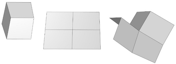
One view of curvature is to regard it as a local deficit or excess of surface area. This is illustrated in Fig. 6.
If we assume faces to be planar and more or less rectangular, then fitting 4 of them together leads to a geometry that naturally lies flat. Fitting three together, effectively taking away a quarter of the surface area, naturally forms a convex, synclastic geometry. And fitting 5 (or more) creates an excess of surface area around the central vertex, producing a wavy, anticlastic geometry (a vertex that has N surrounding faces, is said to valence N. If the valence of a vertex is not 4, it is called a singularity).
Since the sides of our dome are approximately cylindrical, they have almost zero Gaussian curvature. So, although they are (extrinsically) curved, they are intrinsically flat. This means that vertices along the sides should have valence four.
Both ends of the dome are spherical, so have positive Gaussian curvature. To facilitate, one or more vertices with valence three must be added to the mesh topology here.
When optimizing towards planarity, mesh edges tend to align to the principle curvature directions. In the cylindrical middle part,we therefore expect the edges to become horizontally/vertically oriented. At the spherical ends of the dome the situation is different: since every direction on a sphere is a principle curvature direction, there is no preferred orientation for the edges in those regions.
3.3. Final mesh topology
All these considerations left us with two natural candidates for the mesh topology.
- two valence three vertices, one at each end: roof-shaped
- four valence three vertices, two at each end: box-shaped
Apart from having a different number of singularities, they differ in one important regard: in the box-shaped variant all edges run more-or-less horizontal or vertical. In the roof-option however, the topology forces the orientation of the panels to flip from orthogonal down the sides of the dome, to diagonal at the ends.
As already mentioned, the ends of the dome are spherical so every direction is basically a principle curvature direction. A diagonal pattern should therefore work equally well here as an orthogonal one.
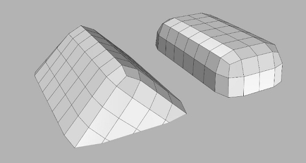
Both topologies (see Fig. 7), nicknamed ‘roof’ and ‘box’, proofed to converge to a good planar geometry that met all constraints. In both cases orthogonality along the edges aids with creating the necessary opening for the terrace. The orientation change of the ‘roof option’ introduces a contrast between the long and short ends of the dome, having more visual appeal, leading to this geometry to be finally chosen.
3.4. Grid density
With the choice of the singularities fixed, there remains only one free parameter for the mesh topology: the number of regular, valence 4, vertices between the singularities. This number will eventually decide the edge size of the panels after optimization. A lower density grid will not only have bigger panels, but also greater kink angles between them.
Since the glass edges must align with the top and sides of the terrace opening, an integral number of panels must fit in this opening, in width as well as in height. This, along with transportation and production considerations, leaves only a small number of options for the grid density and more or less dictates the size of the panels.
4. Solving
With all the boundary conditions defined, solving was done in Grasshopper/Rhinoceros (Rhino) and the Kangaroo plug-in with the help of some custom written goals. Apart from the considerations mentioned above, a number of additional constraints were formulated. To summarize all of them:
- Flatness: Each mesh face must be planar, which is measured as the distance between the diagonals of a face, divided by the length of the diagonals. This is constantly monitored while the solver is running by colouringmesh faces based this value. A face was considered to be planar if the planarity value was below 0.001.
- Closeness to reference surface: This is not an absolute requirement, the mesh is allowed to take on a slightly different shape than the reference shape, as long as the net available floorspace and height don’t suffer.
- Usable floor area: A minimum was set to the net floor area.
- Minimum usable height: Closely related to the previous constraint, both the client and building regulations prescribed a minimal height. Effectively this constraint drove the optimization to a slightly more ‘boxy’ shape than would otherwise have evolved.
- Maximum building height: Municipal regulations set a maximum to the overall building height.
- Squareness: Ideally, the glass panels have more or less square angles and equal edge lengths. This is not a hard constraint either, because enforcing it would not allow for any double curvature in the overall shape.
- Smoothness:Edges that run in the same direction should not zig-zag, but should be more or less co-linear.
- Symmetry: The dome has two symmetry planes, vertices on either side must remain mirrored over those planes. This is an absolute condition.
- Uniform edge length: Together with the squareness goal, this ensures that panels will be of approximately equal size.
- Align edges with the terrace: Since an opening would be made in the dome for the terrace, vertices surrounding the terrace area had to sit on three pre-defined planes, two for the sides, one for the top.
Some of these goals tend to evolve the mesh in the same direction. Some however do not and conflict with each other. The outcome is a compromise between the different constraints. Finding the proper balance between them is a process of trial and error.
The process of solving is now straight forward. First a mesh is created with the appropriate topology and density. It is dimensioned so that it sits roughly in the right spot on the reference surface.
Since it not known a priori how many faces are needed to cover the required surface area, the initial mesh was given some extra rows of faces at the bottom. At the same time the reference surface was extended downward to give the mesh ample room to run past the intended bottom perimeter. Any excess was trimmed off after the relaxation had converged.
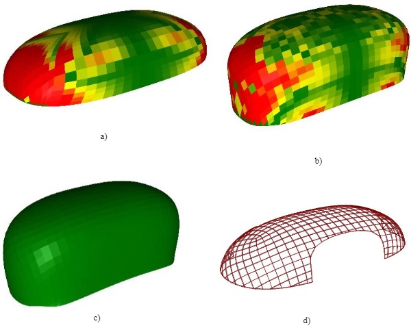
Then the solver is run, monitoring flatness and adjusting weights between the various constraints as needed. As said, this is a process of trial and error, especially given the relatively large number of constraints. Once the mesh geometry satisfied all objective and aesthetic criteria cut-outs for the terrace, back wall etc. were made. The resulting mesh describes the system lines of the glass geometry. This was then handed over to Octatube to develop the detailed design for the glass and steel structure. See figure 8 for the process of geometry optimization.
5. Parametric technical design
Because of the free form of the design, all the parts (steel beams, glass panels, etc.) are uniqueand come together in different geometric ways. If anything in the design was adjusted, all parts changed. After all, everything was connected. At handover to Octatube, the basic geometry was given, but the grid was still under development. This situation raised the following question: How can the technical drawings be efficiently set up and the production prepared, before the basic geometry is established?
From this challenge the idea evolved toautomate the design by developing a parametric tool that could convert the complex basic geometry into a detailed production model. The design was parametrically designed down to the last detail and from these models the productions were managed. By designing the project parametrically, the construction proved to be not only technically feasible but cost effective as well.
5.1. Parametric tool
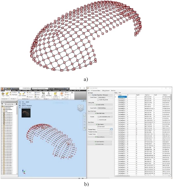
In order to engineer the complex project, a flexible technical software package is required to allow for the unique elements to be modelled efficiently. Within Octatube, Inventor, an Autodesk modelling program, is used in combination with Rhinoceros (Rhino) and Grasshopper. Within this program a tool has been developed by Octatube that can export the wire model to Inventor (Fig. 9).
This parametric tool offers opportunities to play with geometry interactively and in a relatively simple way. By setting up the geometry parametrically, all properties remain continuously adaptable. One of the simplifications this provides is the possibility to develop variants.
A model in Rhino actually consists of points and lines, a schematic representation of the actual construction or geometry: the lines are the beams and the points are the joints. Properties such as profile dimensions and materialization are linked to these elements. After the variant study and optimization, the tool automatically creates all the parts required for production.
The great thing about this design process is that you don't have to start over and over again if something has changed. All you have to do is take the piece that needs to be changed. The most common, regular parts are done with the tool, but other, more complex parts and connection points are not. If you start programming every exception, it becomes too complicated. Normally you make 4 bars and 1 node with all the complexity in it, but in this design process we succeeded to make node-free connections that looked more elegant.
In the end, we designed 9 different types of beams, see figure 10. They differ from each other because of the different connections. The engineer determines in the system where the various connection points will be located, which is the first step. The second step is the manufacturing of the beams and in the third step the building components are grouped and then assembled.
6. Structural analysis
6.1. FEM model
In addition to the technical and production details, also the structural system and loads on the structure are generated through an in-house developed parametric link between Rhino and RFEM via Excel. Thereby maintaining the same flexibility in the definition of the grid during structural development. This allowed the structural optimization of the steel structure to best support the glass in the final developed geometry.
The gridshell is supported by a steel construction by third parties which is placed on the existing roof. An IFC export from the main structural engineer Pieters Bouwtechniek was used to provide the correct rigidity of the supporting steel structure with regard to the support points of the gridshell.
FEM Analysis
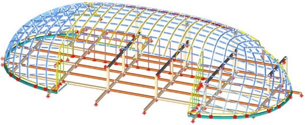
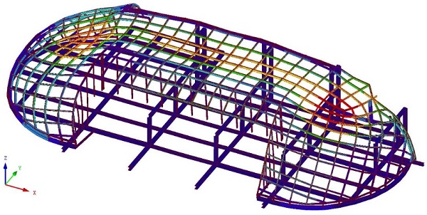
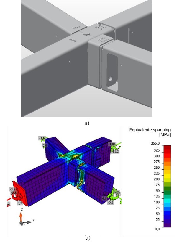
With calculations from RFEM and IDEA Statica the dimensions of tubes (RHS) have been validated. Because the rotational stiffness of the connections is important for the stiffness and strength of the gridshell as a whole, two models were used. These two models represent respectively the lower and upper limits of stiffness of the connections and thus gridshell. The upper limit is assumed as fully stiff joints and serves for the strength calculation of the joints.
The lower limit, used to determine the rotational stiffness, is iteratively determined between RFEM and IDEA Statics. This analysis is performed per individual type of connection detail. In addition, the model with weaker connections is used for testing and verifying the stiffness and stability of the gridshell (Fig. 11). The underlying steel structure is also included as a support structure with respect to the force distribution. This was necessary because approaching the spring stiffness of the vertical supports would be an intensive iterative process as the stiffness would vary per load case.
6.2. Steel connections and glass analysis
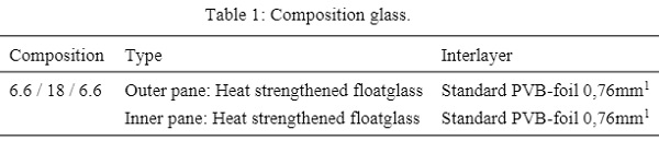
In principle, the dome has only one repetitive structural principle detail. Due to the free form geometry, however, every node is different and so many unique parts are needed. The final design for the Capital C resulted in approximately 1000 different steel elements and 200 different glass panes. Despite of this large number of unique parts, only two roof windows have been calculated. The standard size of 1630x1630 mm1 for strength and stiffness under external loading, the smallest window (385x200 mm1) under isochoric pressure. Analysis was performed using NX-Nastran, through FEMAP as pre-and post-processor. Validation was performed though a shadow calculation in the MEPLA software package.
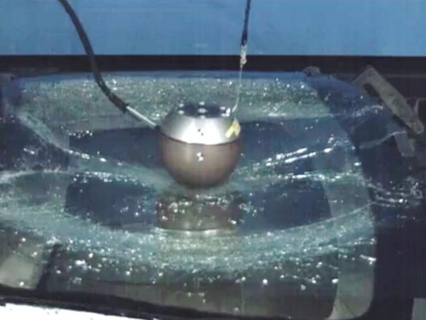
The following loads were included on the roof windows in accordance with NEN2608+C1:2014: Own weight glass, wind, snow, isochoric pressure, imposed maintenance load of 1.0kN/m1 as well as 1.5kN. Because the roof windows can be walked on incidentally, one-sided lateral breakage in accordance with NEN2608 has also been taken into account. Finally, a fall test in accordance with NEN-EN 1991-1-1:2011 was carried out on the roof windows including PV cells.
Composition of the roof glazing:
Not all nodes were calculated. Only the nodes with the measuring loads from the main model were calculated with software IDEA Statica (Fig. 12). The nodes to be checked were selected on: highest unity check in global model, highest moment My, Mz and MT direction, highest axial force as well as highest shear force Vy and Vz. Normative connections are taken both from model with stiff rotation stiffness as well as reduced rotation stiffness (Sj,ini / η).
7. File-to-factory
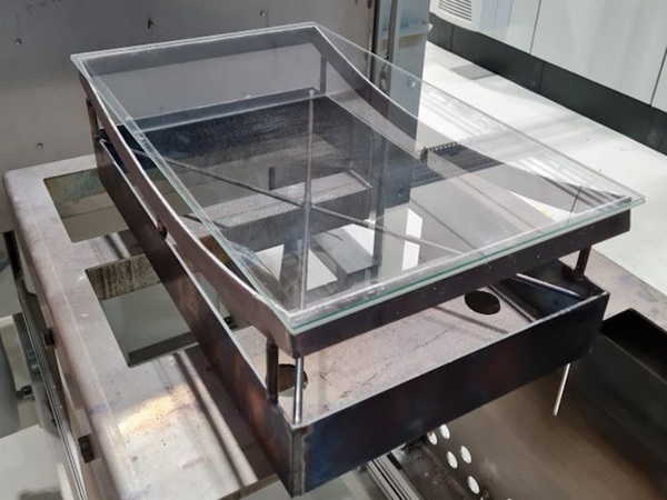
The entire roof structure is file-to-factory produced applying the CNC production technique for the partial production of the tubular parts. The nodes of the dome are designed in such a way that they can be produced dimensionally using a tube laser. In theearly stages of the engineering, two alternatives for the node connection were made and further developed into test productions. This allowed the validation of the technical detail and production method of the node through scale 1:1 production models. With this input, the software was further developed.
The advantage of the proprietary parametric tool is that after changes to the line model, a complete Inventor model can be created quickly, in just four hours, which can be used for production. The model incorporates all facilities, such as holes for lighting, water-mist installation, glass fixing and acoustic panels.
All the tubes are made file-to-factory and are prepared on the palette. All connections are digitized. The adjustable mould is a newly designed component. All complexity automatically comes out of the computer; the height, the position of the part and the degrees. The geometry of the model is extremely complicated because everything is skewed. The nail bed ensures that all complexity of the model can still be mounted in one go.
8. (Pre-)assemblage
With regard to the steel connections of the dome, only one repetitive principle detail has been applied, as previously stated. In this project a system with welded frames from the factory and a bolted connection on site was chosen. The biggest challenge of this method to the chose pre-assembly method is to achieve the exact size of the welded assemblies. When you weld, you have to be able to estimate what the material is going to do due to thermal expansion and subsequent shrinkage of the steel.
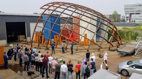
In order to ensure the correct dimensions of the steel structure, part of the structure has been pre-assembled. The test fitting of the most complex part of thedome, the ends, went well and verified the technical engineering and production method (Fig. 13). In addition, the size of the steel structure could already be experienced in the workshop. After the client and design team had inspected the test structure, the structure was disassembled and preserved by means of galvanization and powder coating.
Because the frames are manufactured in the factory, they have a high dimensional stability, high-quality preservation and a high assembly speed on site. The assembly in the city centre of Amsterdam had to be done quickly, because the road could only be closed for two hours a day for hoisting the frames. Despite this restriction, the pre-fabrication of the frames to a high accuracy allowed the steel of the dome to be assembled in only eight days.
9. Conclusion
The gridshell construction with the elegant lines of 'the new diamond' at the Diamond Exchange, could be developed within budget into a slim construction with minimalist details in steel and glass, thanks to the application of parametric tools developed by ZJA and Octatube.
The computational design model for the spatial roof structure was generated to define the architectural design, analyse the geometry and topology, and at the same time provide tools for geometrical and structural optimization. This allowed for the current form of the roof structure to be realized, not only because it was technically feasible, but also cost efficient. This project therefore proves that parametric design and engineering is not only possible but will eventually save time and costs.
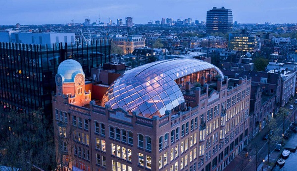
The roof structure is an eye-catcher that draws one’s eye from afar to the Diamond Exchange and follows the lines based on the original design by Gerrit van Arkel. Anyone looking over the roofs of Amsterdam will easily see the transparent curves of the new roof structure from afar. Like a polished diamond, it sparkles in the light allowing the Diamond Exchange to shine again (Fig. 14).
10. References
Broy, M.: Software engineering —from auxiliary to key technologies. In: Broy, M., Denert, E. (eds.) Software Pioneers, pp. 10–13. Springer, Heidelberg (2002)
Cartwright, J.: Big stars have weather too. IOP Publishing PhysicsWeb. http://physicsweb.org/articles/news/11/6/16/1 (2007). Accessed 26 June 2007
Hamburger, C.: Quasimonotonicity, regularity and duality for nonlinear systems of partial differential equations. Ann. Mat. Pura Appl. 169, 321–354 (1995)
Sajti, C.L., Georgio, S., Khodorkovsky, V., Marine, W.: New nanohybrid materials for biophotonics. Appl. Phys. A (2007). doi:10.1007/s00339-007-4137-z