Source:
Challenging Glass 7
Conference on Architectural and Structural Applications of Glass
Belis, Bos & Louter (Eds.), Ghent University, September 2020.
Copyright © with the authors. All rights reserved.
ISBN 978-94-6366-296-3, https://doi.org/10.7480/cgc.7.4496
Authors:
Francesco Laccone, ISTI-CNR, DESTEC-University of Pisa
Luigi Malomo, ISTI-CNR
Nico Pietroni, ISTI-CNR, Universtity of Technology Sydnet
Maurizio Froli, DESTEC-University of Pisa
Paolo Cignoni, ISTI-CNR

Shells made of structural glass are beautiful objects from both the aesthetics and the engineering point of view. However, they pose two significant challenges. The first one is to assure adequate safety and redundancy concerning possible global collapse. Being single-layered, in a shell made of structural glass, the brittle cracking of a single pane can lead to a sudden propagation of failure, up to instability.
The second one is to guarantee cheap replacing possibilities for potentially collapsed components. This research explores a novel concept to address both requirements, where glass is both post-tensioned and reinforced and develops the research on TVT post-tensioned glass beams.
Following the Fail-Safe Design (FSD) principles, a steel reinforcement relieves glass deficiencies (i.e. brittleness and low tensile strength). Following the Damage Avoidance Design (DAD) principles, glass segmentation and post-tensioning avoid the propagation of cracks. Up to now, glass-steel systems were limited to mono-dimensional elements (such as beams and columns) or simple bi-dimensional elements (arches, domes, barrel vaults).
Instead, massive structures are usually realized as grid shells, where glass is used as simple cladding.This research investigates piecewise triangulated glass shells to enable the creation of 3D free-form glass-steel systems, where glass is load-bearing material. Hence, laminated glass panels are mechanically coupled with a filigree steel truss, whose elements are placed at the edges of the panel and act as an unbonded reinforcement.
In a performance-based perspective, these steel trusses can be sized to bear at least the weight of all panels in the occurrence of simultaneous cracks (worst-case scenario). The panels are post-tensioned using a set of edge-aligned cables that add beneficial compressive stress on glass to prevent crack initiation.The cable placement and accompanying pre-loads are derived with an optimization strategy that minimizes the tensile stress acting on the shell.
This optimization procedure also considers the practical constraints involved in the process. The results obtained through this automated procedure are later investigated using nonlinear FE analyses. The resulting structures optimize the total material usage providing contemporarily both transparency and load-bearing capabilities. Post-tensioned shells excel in static performances, achieving high stiffness and good redundancy for the worst-case scenario, and improve the structural lightness and the visual impact with respect to state-of-the-art competitors.
1.Introduction
1.1.Background and motivation
Glass is nowadays the most commonly employed building material for façades and envelopes that require a high degree of transparency. To maximize the immaterial appearance of the structure and to take full advantage of the material usage, the designers have to exploit the load-bearing function to glass (Haldimann et al., 2008). Thus, the ‘opaque’ supporting material has been gradually diminished and the use of specialized supports, embedded connections and components etc. has taken hold.
The transition to structural glass relates to different architectural components: mono-dimensional elements, such as beams and struts (Louter et al.,2012; Louter et al.,2014; Jordão et al., 2014; Martens et al., 2016; Martens et al., 2016b; Engelmann and Weller, 2019; Snijder et al., 2015; Oikonomopoulou et al., 2017; Snijder et al., 2019); or bi-dimensional elements, such as arches (Sobek, 2007), roofs, vaults and facades (Ioannis et al., 2012, Weller et al. 2008, 2009, 2010), or shear walls (Huveners, 2009).In the last twenty years, several strategies have been gradually established in the in order to employ glass for structural purposes, overcoming its mechanical lacks.
Besides the material treatments and lamination of multiple plies, employing steel reinforcements (Martens et al., 2015) has proved to be useful to carry tensile loads, to provide ductility, and to increase the post-breakage behavior. An additional improvement might be provided if steel (bars, cables, strands etc.), is used to install a pre-compression stress on the glass (Martens et al., 2015b). These additional elements may be employed in bonded (Bedon and Louter, 2019) or unbonded configuration.
In spite of these advances, there are only a few exemplars of glass shells that use glass as a primary load-bearing material. Such structures are either limited in size or shape. In fact, for large orfree-form shells, flat or curved glass panels are used as infill material for a grid load-bearing steel structure (Schlaich and Schober, 1996; Adriaenssens et al., 2014).
In response to this lack, the present work develops the research on TVT post-tensioned glass beams (Froli and Lani, 2010; Froli and Mamone, 2014) to thin shells. The objective is to use glass as primary bearing material expanding the possibilities of glass shells for larger spans and more complex geometries, and achieving aesthetic quality, namely more transparency with respect to grid shell competitors, and lightness.
1.2.Shells made of structural glass
Transparent shells made of structural glass are fascinating objects from both the aesthetic and structural engineering point of view. As most architectural materials, glass is produced only in limited sizes and shapes. Therefore such practical constraint poses a significant challenge for material discretization (or segmentation or panelling), and connectivity design. Additionally, great attention has to be dedicated in the design phase to both the panels and their joints, since they are closely related with the structural behavior and the overall stiffness of the shell.
Glass shells can be characterized on the basis of their static behavior (similarly to Romme at al., 2013) and categorized in two groups: strut-and-tie (or tensegrity) behavior, and shell behavior.
Strut-and-tie behavior is founded on a force transfer mechanism which occurs at the nodes. This strategy activates strut zones along glass panels edges, while the steel profiles -if present -act as ties. These systems usually adopt triangular or quadrilateral (usually braced by cables) panels, which are connected at the corners, i.e. with clamping. In return,the nodes are high-stressed zones, hence they need special care in design and assembly. The static response of these structures is akin to grid shells. Examples are the post-tensioned dome at Weltbild Verlag building in Augsburg (Wurm, 2007) and the Maximilianmuseum roof (Ludwig and Weiler, 2000).
Shell behavior is akin to continuous shells, offering continuous global resistance and smooth load transfer. The linear joining system enables an un interrupted transfer of loads between the panel edges. Consequently, it reduces stress concentrations and increases the efficiency of the glass panels. In this case, polygonal panels (usually quads or hexagons) might be preferred to triangles as the larger number of edges offersa major redundancy. Examples of these structures are the Delft dome (Veer et al., 2003), Blandini's dome (Blandini, 2005) and Plate shell structures (Bagger, 2010).
Strut-and-tie structures are more diffuse and built in large-scale exemplars. Hence,they have been extensively tested, including extreme failure scenarios such as the complete collapse of panels. On the other hand, shell structures possess more local redundancy: if a single panel is weakened by a crack, the membrane behavior distributes the load along alternative paths. However, the complete collapse of single or multiple panels is not explicitly managed.
Strut-and-tie structures appear reliable enough to be used for large-size envelopes and for more complex target shapes. So,the present work pursues the Strut-and-tie approach, which employs flat triangular glass panels. Moreover, as glass structures generally adopt additional safety layers to avoid dangerous brittle failures, some steps forward are made also in the conceptual phase. Thus, the concept of dual layer beams explored in TVTs has been developed to a single layer concept as in Froli and Laccone (2018) Hence, this new concept has been applied to a simple and geometrically-predefined volume-forming structures. Indeed, apart from tempering and lamination, these additional safety layers are provided by coupling the panels with both unbonded reinforcements and cables.
1.3.Structural concept and outline
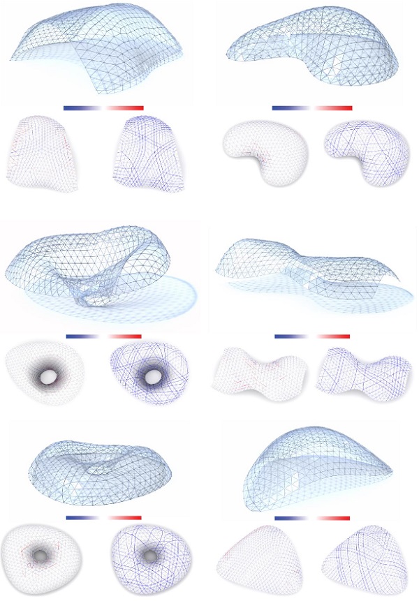
In this work, a specific structural concept (Froli and Laccone, 2018; Laccone, 2019) is applied to realize triangulated glass shells (Fig.1). Following this strategy, glass panels are both reinforced and post-tensioned, addressing two main requirements. Following the principles of the Fail-Safe Design (FSD, CNR, 2012), the first requirement is to assure adequate safety and redundancy for global collapse. Following the Damage Avoidance Design (DAD) principles (Mander and Cheng, 1997), the second requirement is to avoid damages, especially on glass, or at least to guarantee a cheap and easy replacing of collapsed components.
While FSD has been consistently used in glass design, up to now DAD concerns mainly the earthquake engineering field, but some DAD features emerge clearly inthe present system. For example, to minimize the failures on the most vulnerable structural member (glass), target surface is segmented into multiple triangular panels; and to allow safely reversible displacements, rounded corners and dry mono-lateral clamping are employed. Other DAD features of this system are related with the dynamic behavior, i.e.energy dissipation and post-event service ability, and were already observed in TVTs experimental tests. So,such features should be considered alsoin the present shells but will be addressed in future works.
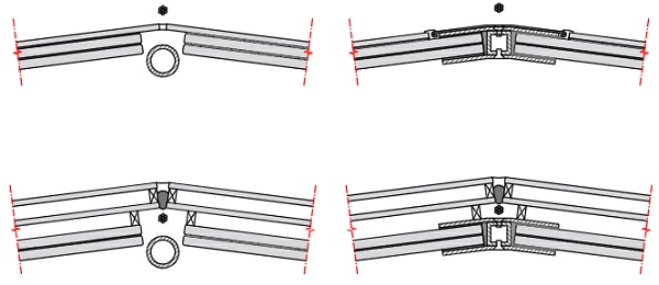
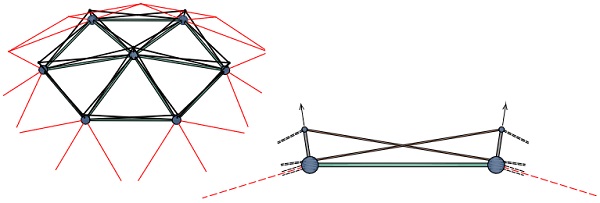
Each pair of adjacent panels shares an unbonded reinforcement, which is bolted onto spatial steel nodes that provide also for the panels’ clamping. Thus, all the reinforcements form a triangulated truss that can be regarded as redundancy barrier to avoid global collapses in case of glass cracking.Post-tensioned cables, which are point-fixed on the same nodes, prevent the glass from carrying tensile stresses and increase the global stiffness. The cables result slightly offset from the main layer of glass as shown in Fig. 2.
As evidenced also in Engelmann et al. (2017), and Hayek et al. (2018), redundancy is an essential requirement to be considered the design of these shells. Extreme scenarios that account also glass cracking should be ensured. The proposed performance-based design philosophy plans to size the reinforcement cross area in proportion to the relevance of the structure, and to support at least the weight of all panels as a dead load.
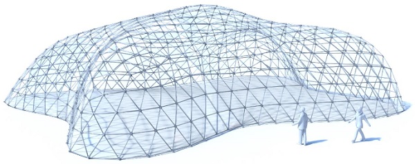
This latter scenario simulates anextreme an after-impact limit case, here defined as ‘worst-case scenario’, in which all panels are supposed collapsed and consequently with null stiffness. The cracked panes are considered unable to fulfil safely any load-bearing task except to transfer their weight to the corner supports. Hence, the mechanics of the shell approaches a grid shell behavior. Beyond this safety function, this skeleton of reinforcements provides a further advantage of realizing a self-supporting structure that can be effectively used in the assembly phase, avoiding the need for a diffuse scaffolding (Fig. 3).
The conceptual design phase of such shells is managed automatically by a bespoke statics-aware algorithm that tackles geometric and manufacturing constraints as well as structural requirements. Starting from a continuous surface, its main objectives are to derive the tessellation geometry and the optimal cables distribution with their respective pre-loads.
Starting from exemplary surfaces, several case studies are optimized and later analyzed with nonlinear FEM simulations to validate the proposed approach and to provide quantitative information on the structural response of these systems. The main purpose is to prove the feasibility of these structures and to compare the results with their grid shells competitors.

2.Automated design framework
2.1.Premises and basic assumptions
Due to the strut-and-tie behavior of these shells, the glass panel can be regarded as a triangulated truss (as per Ludwig and Weiler, 2000) in the conceptual design phase. This triangulated truss is aligned with the edges of the mesh. So, as long as these glass edges are compressed, the stiffness of the structure is increased and the risk of a tensile failure on glass is reduced. This compression may result from external loading (i.e. service load) or induced by post-tensioning forces, exerted by cables along dedicated paths.
The equilibrium of these glass shells is guaranteed even without cables. Being edge-aligned, the reinforcement can sustain tensile forces. Simultaneously, the rounded corners can detach from the nodal cap at each panel vertex and avoid the spread of tensile stresses on glass (this is a mechanism designed and experienced on TVTs). In compression, the glass edges and the reinforcement have in-parallel stiffness. The fact that this kind of shell has already an equilibrium solution, yet not very efficient, is the basic principle of the present methodology. The main idea is that post-tensioning a selected set of cables with a certain pre-load can relieve the shell from traction. It is clear that the problem here poses two indeterminacies: the cable path selection and the accompanying pre-stressing force magnitude.
This optimization is formulated as a mixed integer quadratic problem, whose basic assumptions are thin shell theory, linearity of material and displacement, and negligible loss of pre-load. Input data of the problem are the target surface, its boundary supports, and load.
In common design practice, the base surface of a shell is often the architect’s given input. An ideally optimal structural behavior for compressed discrete shells is obtainable not only by means of a funicular surface, but also with a proper tessellation. Several research works have demonstrated that the static performances of a grid shell are sensitive to the topology, the size and the shape of the cells (Pietroni et al. 2015, Jiang et al. 2017, Li 2017).
However, thanks to the static improvements provided by the cables, the topology of the shell is fixed and does not require further optimization. In this light, a single step of remeshing is sufficient to embed mechanical and geometric limitations on glass panels. However, this approach requires the input surfaces to be funicular or almost-funicular under appropriate boundary conditions. Indeed, since the cables are lying on the surface, potential stress due to bending and twisting cannot be avoided or optimized.
2.2.Methodology overview
Fig. 4 summarizes the main steps of the automated design workflow:
- Surface triangular meshing, to build a quasi-isotropic tessellation made of triangular panels;
- Generation of a reduced model made of linear trusses, in which each edge has a calibrated stiffness that represents the contribution of both glass edges and the reinforcement in between;
- Computation of axial stress on the reduced model induced by SLS uniformly distributed load;
- Geometric generation of all possible cable paths by joining subsequent mesh edges;
- Computation of individual equilibrium solutions of the reduced model subject to each cable loading;
- Superimposition of effect and selection of an optimal subset of cables with appropriate pre-loads such that the overall tensile stress is minimized.
This workflow has been implemented in MATLAB (2018) and C++ using the VCG library (VCGlib, 2018).
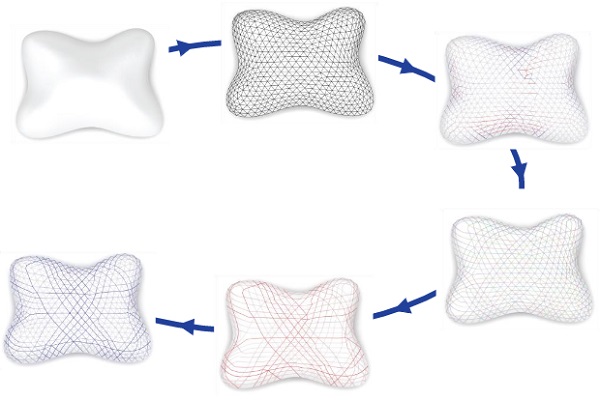
The surface is tessellated with flat triangular faces using the algorithm by Jakob et al. (2015). For a matter of geometry and aesthetics, the positioning of the cables is constrained to overlap the net of reinforcements. Thanks to this improvement, the two opaque components have minimal interference with the transparency of the panels. Consequently, the great advantage is that in a single step of surface re-meshing, glass panels and the grid of reinforcement are automatically set. Lastly, also candidate cable paths may be found since they are enforced to align with a subset of mesh edges.
This remeshing phase allows to constrain the target edge length (or alternatively the total amount of panels) in order to have panel edges with similar mechanical performances and uniform stiffness; to constrain the shape of the faces to be as-regular-as-possible; and to align the boundary edges in order to avoid cutting the panels, which may result in unpleasant tiny or irregular shapes.
A reduced model is employed to obtain a straight forward static response within the optimization routine. In line with the expected static behavior, the shell is regarded as strut-and-tie assembly, where the nodes of the structure are connected by mono-dimensional truss elements, i.e. the edges of the mesh. These are equivalent trusses, concentric with the reinforcement axes, whose stiffness sums the contribution of both the steel reinforcement and the portions of adjacent glass panes. These elements have a marked nonlinearity depending on the sign and magnitude of loading. However, for the sake of simplicity, the stiffness is linearized and reduced to be on the safe side. Itscalibration is referred to Section 3.5.
Since the structures are thin shells, the membrane hypothesis applies. Consequently, the reduced model possesses only in-plane stiffness (truss elements and frictionless nodes) and manifests large sensitivity with respect to loads that are not-perfectly funicular. Alimited out-of-plane resistance is provided through a low-stiffness secondary net of trusses, particularly to face the scenario of cables loadingor to stabilize the solution in case of slightly-inaccurate membrane loading.
A uniformly distributed load isapplied at the nodes, so the bars are only axial stressed. As a result of this linear static analysis parts of the rods are compressed and other tensioned. The tensioned bars highlight the areas of the shell where external post-tensioning (provided by the cables) should be applied.
The well-known objective of pre-stress is to stiff the shell and to enhance the efficiency of the structure. Additionally, as inthis case, pre-stress is used to eliminate or to significantly reduce the overall tension. Technically, once the shell is assembled the pre-stress isconferred by post-tensioning via cables. Sliding cables are point fixed at the nodes, so that their configuration results in a 3D polygonal line described by subsequent glass edges.
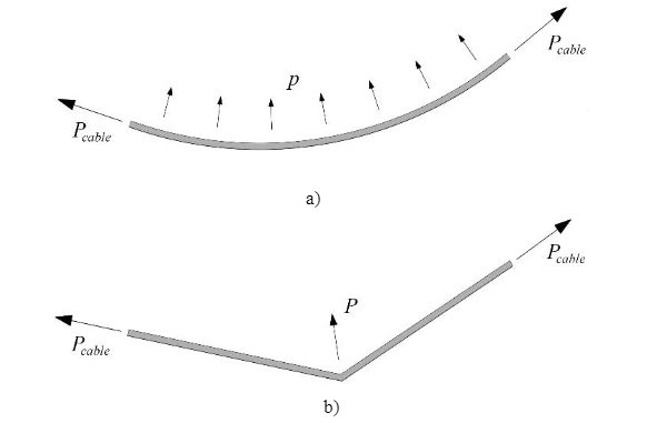
The post-tensioning force is generated on the cables by bolting threaded extremities (for low pre/load magnitudes), or by using stressing jacks at extreme anchoring points, usually atthe boundaries of the structure. Apart from this extremity component, forces derived by thechange of direction of a cable (as per Fig. 6) are more relevant especially in the cases of spatially curved structures.
Depending on the cable path, two main cases can be distinguished: if the cable is smoothly deviated, its action results in a uniformly distributed load p (such as in post-tensioned concrete with parabolic cable path, (a) of Fig.6); if the cable is deviated punctually, it assumes the configuration of a polyline, at whose nodes a punctual force Pis exerted (such as in external post-tensioned structures or harped tendons in prestressed concrete, (b) of Fig.6).
The latter case is compliant with the geometry adopted in the present methodology. Forces due to friction develop because in all points where the direction changes tangential forces are transmitted to the structure. These forces reduce the pre-stress causing the so-called loss due to friction.
In a first step, a candidate set of cables is generated on the re-meshed surface by iteratively chaining sequences of adjacent edges along collinear directions, until all the edges have been explored. A cable can either terminate at the boundary or it can create a loop. For efficiency of post-tensioning, the cables that include kinks with a deviation angle larger than 40° are discarded, as they may induce undesired shear on the surface.
Once the geometry of the cable is known, its equivalent load on the nodes P can be trivially computed assuming that each cable has a uniform tension, i.e. Pcable=1.0 kN. Under linearity hypothesis, the magnitude of pre-load can be varied by simply applying a load multiplier for the unitary equivalent load. A single candidate cable can induce both tension and compression on the reduced model. The ability of each subset of candidate cables to reduce traction globally from the trusses can be iteratively checked via superimposition of effects on the reduced model. The selection of the optimal cable setting and all implementation details are in Laccone et al. (2019).
2.3. Design cases and optimization results
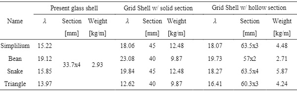
This iterative optimization process has been tested on several datasets, as shown in Fig. 7 and described in Tab. 1. For sake of consistency, all the examples shown in this paper have the same target edge length of 1.0 m, and also same glass stratification, same reinforcements and cables. The maximum pre-load for cables is constrained to be smaller than 40kN and the maximum compression for the equivalent truss in the reduced linear model tobe larger than −30kN to avoid buckling.
The steel reinforcement has a hollow profile with 33.7 mm of outer diameter and 4 mm of thickness. The reason for the hollow profile is that it is not sensitive to buckling for low-level loads (either in collaboration with glass and in the WCS), but other strategies for cross-section and restraint selection can be covered. Cables are 15 mm-diameter ropes, and glass panes are PVB-laminated 8+1.52+8 mm thick.
Table 1: Metrics and analysis results on different models with reference to Fig. 7.
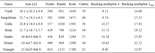
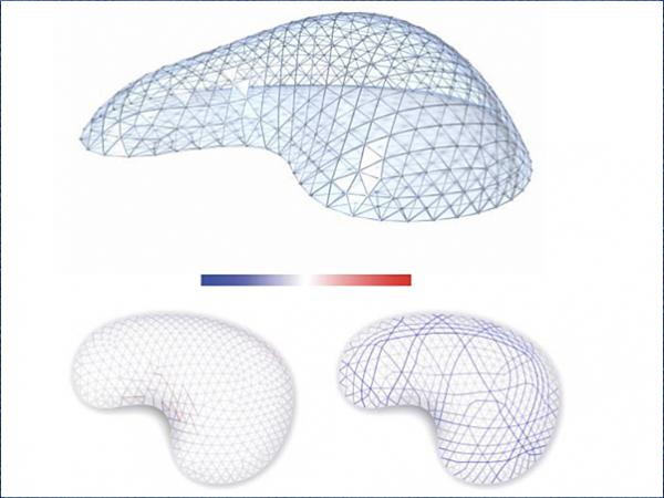
Fig. 7 shows that the positive axial forces on the reduced model is considerably reduced by the iterative optimization process, as a consequence the equivalent truss model is almost-exclusively supporting compression. Moreover, limiting the compression to stay above a lower boundary optimizes implicitly the material utilization. If an optimized post-tensioning is applied, the buckling multiplier increase up to about the 70% with respect to the same non-post-tensioned shell, resulting in a sensible increase of robustness (Tab. 1). The buckling multipliers in Tab. 1 are evaluated by means of a linear buckling analysis (eigenvalue analysis) for a consistent comparison with the non-post-tensioned shells (and later in Table 3 with grid shells).
3. Nonlinear investigations
3.1. Materials and methods
From the case studies optimized in the previous step, nonlinear models are built in the FEM package Straus7 (G+D Computing, 2005) with the aim of performing analyses that take into account mono-lateral connections (contact non-linearities), shrinkage in the post-tensioning phase and geometric nonlinearities. These tests are not meant to be exhaustive of all physical phenomena, but only to catch the shells global performance and to verify the load case that has been object of the optimization.
The modelling phase has been supported by the TVT state of the art (Froli et al., 2017), especially for the calibration of contacts, since the structural members and loads here applied are comparable. In particular, the ‘simplified model’, which is calibrated to give similar static response with respect to more refined models, is adopted. Although simplified, these analyses already involve a considerable number of variables, so material non-linearities have been neglected. Characteristic values are adopted for materials.
The geometry of the model is generated by means of a grasshopper script with the mesh and the cables indices as input. For the sake of simplicity, the panel is supposed to lie in the same plane of its three-side reinforcement, the eccentricity with respect to this plane that the panels potentially have (see the detail design of Fig. 2) is neglected.
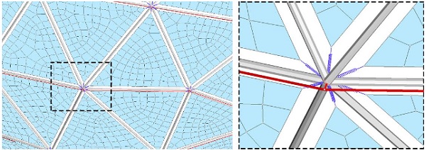
Steel reinforcements are modelledas beams, however, both bending and torsion are negligible. Steel nodes, where rods merge, are dimensionless nodes, with the additional effect of augmenting the slenderness of the rods, ignoring the node encumbrance (Fig. 8). The glass-to-steel link is a spring with axial capacity (to resist deformations along its axis), lateral (for all lateral movements) and twist resistance (about its axis). The bending constraint that in real cases, is given by the panels’ steel caps is not included.
The modelling of panel moreover suggests that peak stresses that may arise in the tip closeness because of force concentration. Stress verification is meaningless in this phase and are demanded to successive detailing design. Monolithic plate elements are used for glass panes and are re-meshed withan eight-node quadrilateral FE (Quad8) of target size of 5% of the panel side length. The cables are modelledas tension-only segments, which nodes are assumed to be rigidly coupled to the frame nodes. In the current analysis border conditions for all models are pin joints and correspond to their boundary vertices.
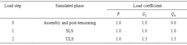
The cable pre-load is applied through tension-only elements simultaneously with the dead load. The dead load G1 is automatically computed from the element density, moreover, an additional uniformly-distributed vertical Qk = 1.00kN = m2 loading acting on the panels (in the direction of gravity, i.e. snow loading) is superimposed. In the post-tensioning load case P, the cables pre-load deducted from the optimization phase are effectively applied. The loads of the three-step analysis according with the Italian national code MIT (2018) are summarized in Tab. 2.
Table 2: Load step definition for the nonlinear analyses.
For case study, the extracted results are: (i) axial forces and stress field in the post-tensioning phase (in order to check if glass effectively undergoes compression stresses in the assembly); (ii) axial forces and stress field at SLS; (iii) axial forces and stress field at the ULS; (iv) redundancy rate R. The latter quantity is obtained as the ratio between the safety factors for the ULS load combination of the structure SFhyb over the safety factor in the WCS SFwcs. The WCS scenario is simulated in a separate model where the plates are substituted with load patch elements, namely non-structural elements for area-load distribution.
3.2. Global analyses
The results of nonlinear analyses are shown in Fig. 9. All datasets, regardless their size and shape, manifest similar characteristics and achieve all objectives. The stress field on the panels complies with the output of the optimization phase, namely thetractions are very limited, especially at the SLS, and located similarly in restricted areas. The peak values are usually reduced at the SLS, which has been the loading phase object of the optimization.
Glass pre-compression is diffuse and uniform in the assembly phase, while from the SLS phase, de-compression spreads and high stresses are located in adjacency to post-tensioned edges. From the material utilization point of view, the solution adopted is optimal because the elements are uniformly stressed, as it will be noted also from the comparison with the structure at WCS.
In all cases, the safety factorsfor the steel componentsresult SFhyb>3.00 and SFwcs>1.00, with a redundancy always larger than unitary R>1.00 (see section 3.4 for a discussion on redundancy). For an effective comparison of both the design scenario, the full ULS load is considered. As a consequence, the comparison of axial forces can be then considered as a comparison between the present glass shells and grid shells in terms of steel utilization and stress map. In this regard, the main point of the present structures is that the spectrum of axial forces is very reduced with the center of distribution on negative values, while at the WCS (or for a grid-shell-like behavior) a larger and scattered range of values can be noted. The system efficiency is enhanced.
3.3. Comparison with grid shells
Grid shells are the principal competitors of the present glass shells. In grid shells the only load-bearing material is steel. Effective comparison criteria cannot be based on the resistance of steel components, because it would penalize grid shells. Instead, the two structures can be compared if they both have the same buckling multiplier.
So, for each case study the cross-section properties of the grid shell are varied (among those present in commercial catalogues) to match the value of the buckling multiplier λopt (with ref. to Tab. 1). Tab. 3 collects the results coming from case studies in which a global buckling shape manifests as at the first buckling mode. On the other hand, case studies that manifest local buckling failures (e.g.,panels instability) are evidently excluded.
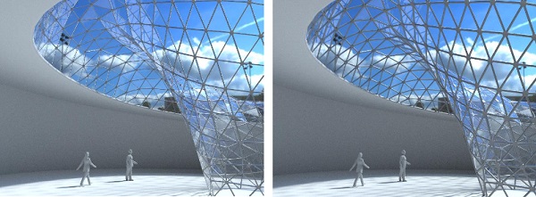
Using hollow steel beams in grid shells, both the outer diameter and thickness can be tuned. Usually, it emerges that comparable performances are obtainable if the diameter is doubled. In this case, the total weight is also roughly doubled and the overall transparency of the structure will be inevitably affected by the new size of the beam. Fig. 10 reports images generated with same rendering settings in both cases, namely reinforced and post-tensioned glass shells and grid shell (with doubled steel section).
Instead, the use of solid steel beams for grid shells results in a more compact cross-section, which is however bigger than the hollow reinforcement of the glass shell case, but, even worse, the total weight of the steel will be roughly quintupled. Making use of glass structurally demonstrates advantages in terms of both visual and structural lightness, because of respectively the small impact on transparency and the high ratio between load capacity and own weight.
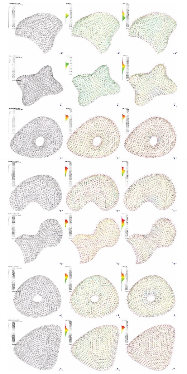
Table 3: Cross-section properties of grid shell with comparable buckling multiplier.
3.4. Estimation of redundancy
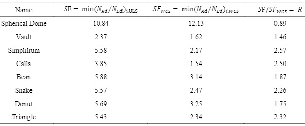
Due to the relevance of the investigated structures, the reinforcement has been realistically sized to achieve a safety factor larger than unitary in the WCS. To be on the safe side,in this latter scenario, the full loading at the ULS is considered, and consequently it has more sense to compare both the design scenario and the WCS at the ULS.
In Tab.4 are collected the safety factors, SF and SFwcs achieved at the maximum-stressed reinforcement element in both cases. In all datasets, a sensible raising of these factors emergesat the ULS with respect to the WCS. In the last column, R=SF/SFwcs, ratio of the two values, represents a measure of the redundancy level. As emerging from the literature (i.e. in Weller et al., 2008), a safety factor for steel components in structures similar to the present ones is meanly 3.0. Consequently, this value can be assumed as objective function that iteratively updates the sizing of reinforcement to match it.
For a more effective comparison, in the present design exploration the size of the reinforcement is kept constant. However, this choice lead to ‘undesired’ effects: (a) the Vault dataset, due to its dimension and shape, achieves a SF=2.37 that is lower than 3; (b) the Spherical Dome dataset (with ref. to Fig. 3) has a R value lower than 1, namely the truss network has more safety margin in the WCS than at the ULS.
In particular, this latter effect is due to the oversized reinforcement cross section with respect to the design demands, as shown by the high SF values, which lead to a stiffer skeleton (the Spherical Dome case study is smaller with respect to other examples, i.e. 6.67 x 6.67 x 3.34 m). Locally, apart from the compression generated by the vertical loads, some rods are further overloaded by the post-tensioning forces. These results also prove that a correct reinforcement calibration is paramount for allowing the development of the desired mechanism.
Table 4: Safety factors and redundancy rate on different models.
Another redundancy estimation has been proposed in Engelmann et al. (2017), and Hayek et al. (2018). The authors considered the scenario in which glass panels fail in maximal-normed displacement areas of the first buckling mode. A failed panel is simply removed creating a new model that can be analyzed to iterate the procedure. Thus, they explored progressive failures by removing at each step one upto four broken faces, until a maximum of four panels is removed or until the shell is not stable anymore. However, this method requires a more detailed model and goes beyond the objectives of this work.
3.5. Local analyses
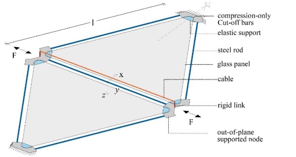
In this section, an elementary unit of the system is analyzed. This unit is made of fivesteel reinforcement rods, surrounding twosymmetrictriangular panes, and merging into fournodes. The central edge shared among the two glass panels can be eithertensioned or compressed. Additionally, itispost-tensioned by means of a cable segment. The static scheme is depicted in Fig. 11.
This setting idealizes a generic reinforced and post-tensioned mesh edge of the system, although real cases are clearly more complex because of the spatiality of the problem and non-symmetrical geometry and load. However, the results are crucial for evidencing the nonlinearity of the problem. The force-displacement relation is computed from two exemplary design cases that are based on the same geometry, but differfor cable pre-load magnitude. The homogenized section method is used to provide quantitative results.
A more detailed modelling is adopted to describe the response of the elementary unit. The basic difference with respect to the previous global models is that the glass-to-steel ontact is fully included. The behavior of the spacers is accounted by means of compression-only Cut-off bars, arranged radially to the rounded glass vertices of the panels, which are modelled with their actual geometry.
In the two design cases, the cable, which is a 15 mm-diameter Cut-off-bar with a brittle failure behavior occurring at 50 kN, is post-tensioned at 20 kN in the first case and at 40 kN in the second. In both cases, the panels lie in the same planeof the rods, and gravity loading g1 is acting in the direction aligned with their normal. The panel corners are installed onto elastic supports of stiffness k =85 N/mm2 (deduced from a detailed 3D model of the clamping contact, as in Laccone et al., 2020). Test loads F are applied on the central nodes, which are over-resistant with respect of all other elements. A two load steps analysis include the Load step 0, with gravity and post-tensioning; and the Load step 1, where the force F is increased up to failure (with positive and negative sign).
The two response curves (Fig. 12) are centered with respect to the end of Load step 0, so essentially the graph reports the response of an equivalent already-post-tensioned rod. For a quantitative comparison, a dashed line reports the analytical response of the only steel rod actually included in the model (external diameter 33.7 mm; thickness 4 mm), whose stiffness ER is given by:

where Es is the steel Young’s modulus, As the cross-section area and L the length of the rod. Moreover, it results useful for the discussion to include the value of the tensile stiffness ER+C of the rod in parallel with the cable.

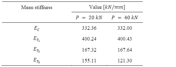
Both response curves can be approximated as a multilinear relationship that is function of the load F and its sign. If the interpolating line is found on each segment (C, T1, T2, T3), it is possible to evaluate the mean stiffness from the slope value, reported in Tab.5. Apart from the last value of the mean stiffness ET3, both models present same stiffness values in the other three segments. In compression (C), the rod results very stiff (EC) and behave almost elastically up to 80−90 kN in both cases.
On the positive side, the first segment of tension T1 is even stiffer (ET1). Here, the panel is decompressing. Additionally, the steel rod retrieves its pre-compression, even though very limited because pre-compression is adsorbed almost exclusively by glass. Then, the rod is tensioned in parallel with the cable. In the second step T2, the slope changes with the end of the decompressing phase, so glass manifests only parasite tensile stresses, while the steel components are tensioned. The detachment of Cut-off bars simulating the compression-only spacers located at the caps cavity starts andcompletes with a nonlinear shifting at the end of T2, and a slightly reduced stiffness (ET3 instead of ET2). Thus, for the P=20 kN curve, the stiffness gradually approaches the ER+C value.
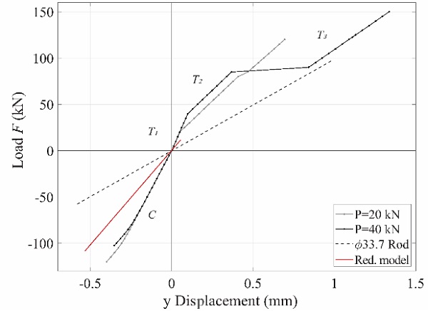
The main differences between the P =40 kN curve with respect to the P =20 kN curve are that (a) the length of the segments is different, and as it can be easily imagined this is a function of the post-tension rate; and (b) there is a marked nonlinearity occurring between the segments T2 and T3, which is interpreted as the failure of the cable due to the high post-tensioning stress rate. In fact, the last part of the curve has a stiffness ET3 that results lower than ER+C, and, excluding secondary effects caused by glass tensioning, approaches the ER value.
Table 5: Mean stiffness of each segment of the load-displacement curves in Fig. 12.
Observing Fig. 12, it clearly emerges that the post-tensioning magnitude affects the length of segments in the ideal response curve. Noting that the curves are aligned to have the end of Load step 0 at the origin of axes, it could be imagined that they perfectly overlap if the starting of Load step 0 is instead located at the origin. In extreme simplification, to have an idea of the effect of different post-tensioning rates the response curve can be simply shifted for a value proportional to the increment of post-tensioning (i.e. with respect to the P = 20 kN curve).
Although the problem remains nonlinear and more complex, it seems that the ultimate limit load, i.e. for compressive failure, is not sensitive to the post-tensioning rate. This result is in line with usual post-tensioned structures outcomes and was already found in the TVT experience (Froli and Lani, 2010). On the tension side, the stiffness and the limit load are function of the rod and the cable stiffness and resistance.
These analyses aim at highlighting the need for a careful design and a posteriori verification because the nonlinearity is not managed in the conceptual phase, nor the inherent anisotropy of the structure caused by the non-equal mesh edge behavior and non-uniform distribution of post-tensioning on the edges. Indeed, the methodology presented in section 2 relies on a linear stiffness (red line in Fig. 12) to be used on the reduced model.
The value is obtained from a linear regression of the nonlinear response (with no post-tensioning), reduced by the 20% to be on the safe side. However, on the basis of several experiments on all datasets it has been observed that the linear stiffness has a low sensitivity on the final optimum result. This effect is related the geometry of the mesh, which is an almost-isotropic triangulation, able to produce a quasi-isotropic shell. The advantage is that the sizing of the components should be slightly adjusted in a detailed design phase without altering the optimum found.
4. Conclusions
Transparent shells can be realized as piecewise assembly of structural glass triangular panels both reinforced with unbonded steel rods and post-tensioned by cables. The specific concept here employed provides safe highly-transparent and material-efficient structures with broad applicability, also in the context of free form architecture.
These shells can be effectively sized by using some simplified hypotheses (i.e. linearity, superimposition of effects etc.). However, the occurrence of local mechanism has to be checked accurately using more detailed models. Nonlinear static analyses on structures generated according with theoutlined static concept and generative workflow demonstrate the robustness of the structural system.
The structural safety can be deemed appropriate since the panel is mostly compressed at the SLS, and the structure is uniformly and diffusely loaded. A high redundancy with respect to the WCS is stated within the investigated case studies. However, the response of these glass shells subject to other load cases, in particular for asymmetric loadings are still to be considered.
These structures might fit the target category of the intermediate-spanned thin-shell structures, and they can be competitor of grid shells. Moreover, making use of structural glass demonstrates advantages in terms of both visual and structural lightness.
5. Acknowledgements
This research was partially funded by the Italian PRIN project DSurf (grant no. 2015B8TRFM).
6. References
Adriaenssens, S., Block, P., Veenendaal, D., Williams, C.: Shell structures for architecture: form-finding and optimization, Routledge (2014)
Bagger, A.: Plate shell structures of glass: Studies leading to guidelines for structural design. PhD thesis, Technical University of Denmark (2010)
Bedon, C., Louter, C.: Structural glass beams with embedded GFRP, CFRP or steel reinforcement rods: Comparative experimental, analytical and numerical investigations. J. Build.Eng.22, 227-241 (2019)
Blandini, L.: Structural use of adhesives in glass shells, PhD thesis, Institut für Leichtbau Entwerfen und Konstruieren (ILEK), Universität Stuttgart (2005)
CNR 2012. Istruzioni per la progettazione, l’esecuzione e il controllo di costruzioni con elementi strutturali di vetro. Consiglio Nazionale delle Ricerche CNR-DT 210/2012
Engelmann, M., Hayek, I. E., Friedreich, O.,Weller, B.: Post-breakage performance of a spherical glass shell, Proceedings of IASS Annual Symposia (Vol. 2017, No. 8, pp. 1-6). International Association for Shell and Spatial Structures (IASS) (2017)
Engelmann, M., Weller, B.: Bending Tests on Spannglass Beams: Comparisonwith Post-Tensioned Concrete Structures. J. Struct.Eng.145(10), 04019099 (2019)
Froli, M. and Lani, L.: Glass Tensegrity Trusses. Struct.Eng.Int.N°4, 436-441 (2010)
Froli, M. and Mamone, V.: A 12 meterlong segmented, post-tensioned steel-glass beam (TVT Gamma). Challenging Glass 4 & COST Action TU0905 Final Conference. London: Louter, Bos & Belis (Eds.) Taylor & Francis Group, 243-251 (2014)
Froli, M., Laccone, F., Maesano, D.: The TVT glass pavilion: theoretical study on a highly transparent building made with long-spanned TVT portals braced with hybrid glass-steel panels. Buildings, MDPI, 7(2), 50 (2017)
Froli, M., Laccone, F.: Hybrid GLAss-Steel Stele (HYGLASS): Preliminary Mechanical Study on a Smart Tetrahelical Cantilevering Tall Structure. Challenging Glass Conference Proceedings, v. 6, p. 611-616 (2018)
Froli, M., Laccone, F.: Static concept for long span and high-rise glass structures. J. Architect.Eng.ASCE, 24(1): 04017030 (2018)
G+D Computing: Straus7 User’s Manual. G+D Computing, Sydney (2005)
Haldimann, M., Luible, A., Overend, M.: Structural use of glass, volume 10, Iabse (2008)
Hayek, I. E., Engelmann, M., Friedreich, O., & Weller, B.: Case study on a spherical glass shell, J.Int.Assoc.Shell Spatial Struct.59(2), 105-118 (2018)
Huveners, E. M.: Circumferentially adhesive bonded glass panes for bracing steel frames in facades. PhD thesis, Technische Universiteit Eindhoven (2009)
Ioannis, S.M., Simon, D., Nhamoinesu, S., Overend, M.: Investigation of double-layer tensegrity glazing systems, IASS Annual Symposium –IASSAPCS 2012 Seoul, South Korea. (2012)
Jakob, W., Tarini, M., Panozzo, D., Sorkine-Hornung, O.: Instant field-aligned meshes. ACM Trans. Graph., 34(6), 189-1 (2015)
Jiang, C., Tang, C., Seidel, H. P., Wonka, P.: Design and volume optimization of space structures. ACM Transactions on Graphics (TOG), 36(4), 1-14 (2017)
Jordão, S., Pinho, M., Martin, J.P., Santiago, A., Neves, L.C.: Behaviour of laminated glass beams reinforced with pre-stressed cables, Steel Constr. 7, 204-207 (2014)
Laccone, F., Louter, C., Froli, M.: Glass-Steel Triangulated Structures: Parametric Nonlinear Finite-Element Analysis of In-Plane and Out-of-Plane Structural Response of Triangular Laminated Glass Panels, J.Architect.Eng.26.1: 04019022 (2020)
Laccone, F., Malomo, L., Froli, M., Cignoni, P., Pietroni, N.: Automatic Design of Cable-Tensioned Glass Shells, Computer Graphics Forum (2019)
Laccone, F.: Reinforced and post-tensioned structural glass shells: Concept, morphogenesis and analysis, PhD thesis, University of Pisa (2019)
Li, W., Zheng, A., You, L., Yang, X., Zhang, J., Liu, L.: Rib‐reinforced Shell Structure. Computer Graphics Forum, Vol. 36, No. 7, pp. 15-27 (2017)
Louter, C., Belis, J., Veer, F., Lebet, J.P.: Structural response of SG-laminated reinforced glass beams; experimental investigations on the effects of glass type, reinforcement percentage and beam size, Eng.Struct.36, 292-301 (2012)
Louter, C., Cupać, J., Lebet, J.P.: Exploratory experimental investigations on post-tensioned structural glass beams, J. Facade Des.Eng. 2(1-2), 3-18 (2014)
Ludwig, J.J., Weiler, H.-U.: Tragstrukturen aus Glas am Beispiel einer Ganzglastonne-Schalenkonstruktion ohne tragende Stahlunterkonstruktion am Maximilianmuseum in Augsburg, Bautechnik, 77(4), pp. 246-249 (2000)
Mander, J. B., Cheng,C.-T.: Seismic resistance of bridge piers based on damage avoidance design, Technical Report Technical Report NCEER-97-0014, University at Buffalo, State University of New York, (1997)
Martens, K., Caspeele, R., and Belis, J.: Development of composite glass beams –a review. Eng.Struct.101, 1-15 (2015).
Martens, K., Caspeele, R., and Belis, J.: Development of reinforced and posttensioned glass beams: review of experimental research. J.Struct.Eng.142(5), 04015173 (2015)
Martens, K., Caspeele, R., Belis, J.: Load-carrying behaviour of interrupted statically indeterminate reinforced laminated glass beams, Glass Struct.Eng. 1(1), 81-94 (2016)
Martens, K., Caspeele, R., Belis, J.: Numerical investigation of two-sided reinforced laminated glass beams in statically indeterminate systems, Glass Struct.Eng. 1(2), 417-431 (2016)
MATLAB version R2018a, The MathWorks Inc., Natick, Massachusetts (2018)
MIT 2018. NTC18 -Norme tecniche per le costruzioni. Ministro delle infrastrutture e dei trasporti.
Oikonomopoulou, F., van den Broek, E. A. M., Bristogianni, T., Veer, F. A., Nijsse, R.: Design and experimental testing of the bundled glass column. Glass Struct.Eng.2(2), 183-200 (2017)
Pietroni, N., Tonelli, D., Puppo, E., Froli, M., Scopigno, R., Cignoni, P.: Statics aware grid shells. In Computer Graphics Forum Vol. 34, No. 2, pp. 627-641 (2015)
Romme, A., Sørvin, I., Bagger, A.: Spaceplates building system. In Structures and Architecture (pp. 1401-1408). CRC Press (2013)
Schlaich, J. and Schober, H.: Glass-covered grid-shells. Struct.Eng.Int.6(2):88–90 (1996)
Snijder, A. H., van der Linden, L. P. L., Goulas, C., Louter, C., & Nijsse, R.:The glass swing: a vector active structure made of glass struts and 3D-printed steel nodes. Glass Struct.Eng.1-18 (2019)
Snijder, B., Dierks, D., Huveners, E., Spoorenberg, R.: Suppressing Buckling of a Slender High-Strength SteelColumn by Using Glass Panes. Struct.Eng.Int.25(3):249–257 (2015)
Sobek, W.: Strutture in vetro, Archi: rivista svizzera di architettura, ingegneria e urbanistica, Swiss review of architecture, engineering and urban planning. 24-31 (2007)
VCGlib. a C++, templated, no dependency, library for manipulation, processing and cleaning of triangle meshes. Visual Computing Laboratory, ISTI-CNR Pisa, Italy available at: http://vcg.isti.cnr.it/vcglib(2018). Accessed: 2018
Veer, F. A., Wurm, J., Hobbelman, G.J.: The design, construction and validation of a structural glass dome, Proceedings of the Glass Processing Days, Poster, 12, vol. 12 (2003)
Weller, B., Reich, S., Ebert, J., Krampe, P.: Testing for individual approval of a vault roof with in-plane loaded glass panes, Proceedings of the International Association for Shell and Spatial Structures (IASS) Symposium 2009, Valencia. 2990-3001 (2009)
Weller, B., Reich, S., Ebert, J.: Testing on Space Grid Structures with Glass as Compression Layer, In Proceedings of the Challenging Glass Conference, Delft. 155-162 (2008)
Weller, B., Reich, S., Ebert, J.: Transparentes Raumstabwerk über dem Innenhof des Berliner Reichstagspräsidentenpalais, Stahlbau. 79(S1) 3-9 (2010)
Wurm, J.: Glass Structures, Design and Construction of Self-supporting Skin, Birkhauser, Berlin (2007)