This paper was first presented at GPD 2019 by Sophie Pennetier, Alessandro Ronfini and Josephine Stoddard.
It documents the team’s research on ultra-thin glass, from a sculpture in 2017 to the development of a pavilion in 2018 and 2019. Explorations include development in prototyping, cutting methods, lamination techniques and connections specific to ultra-thin glass.
Introduction
Ultra-thin glass comprises glass below 1-2mm in thickness. As such, it is very flexible. For example, ultra-thin glass of 0.1mm thickness will bend similarly to a regular sheet of paper, which is also typically 0.1mm thick. Ultrathin glass is either produced by “Draw Down” [1] or “Fusion Draw” [2]. These processes, developed in the 60’s, consist of stretching the glass vertically before rolling it up in spools. Ultra-thin glass typically comes in spools 1.3m wide, in length of 300m.
The main suppliers are Corning, AGC and Schott. Unless otherwise specified, the ultra-thin glass product used for this research is Willow Glass by Corning. It is made of alkali-free borosilicate manufactured in 0.1 and 0.2mm thicknesses. In the current market, applications for ultra-thin glass include automotive interior glass, consumer electronics, LCD display technologies, electric wafers and interior architectural glass.
In most applications the glass is mounted to a substrate. For instance, interior architectural applications with small thermal loads allow for bonding to material of dissimilar Coefficient of Thermal Expansion (CTE) such as aluminum or wood fiberboard (MDF). It is essential to laminate the glass to ensure post-breakage redundancy for its use in the build environment, as it breaks in large shards, similar to annealed glass.
The potentials of ultra-thin glass in facades include light weight dual skins, retrofitting, curved facades or Insulated Glass Units (IGU) with multiple cavities. Furthermore, the potential of using glass material that comes in spools of 300m is unfathomable.
Cold bending glass is a process of deforming glass elastically at room temperature, in opposition to hot bending which involves slumping glass at high temperature. The shape of cold bent glass needs to be maintained by connections: if the connecting elements are removed, the glass springs back, completely regaining its original flatness. Many projects use cold bent glass panels, such as the IAC Headquarters in New York, the Strasbourg Railway Station, or the One Blackfriars tower in London.
For each of these projects the components retaining the glass, whether it is the supporting structure, the interlayer ensuring shear transfer, or the seal of the IGU frame, must be designed to sustain high spring-back forces which depend on the stiffness of the bent glass system. Due to its thinness, flat ultra-thin glass has very little stiffness, so it results in very low spring-back forces when cold bent. Furthermore, curving glass augments geometrical stiffness which enhances serviceability.
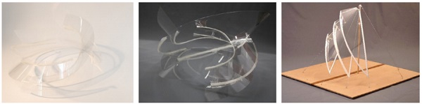
The research topics discussed herein were inspired by the advancements in ultra-thin glass research attributed to Pennetier’s sculpture project in 2017 [3]. The sculpture is 700mm high and 750 x 750mm in plan. It showcased an iterative analysis of geometry and internal forces can result in a rigid free form design and a process scalable to the build environment. It combined 6 nonlaminated 0.2mm glass panels, connected by means of 3D printed PLA V shaped profiles.
The glass was supplied by Coresix, a glass manufacturer located in Virginia (USA) masters of cutting ultra-thin glass. The V profiles were printed in 250mm lengths on parallel printers, an economical approach to produce the connections (further discussed in section 3). While these materials were adequate for prototyping and research on the glass itself, a few lessons were drawn from this project:
The connections of the disjointed V sub-profiles created soft hinging locations where the glass broke (Fig.2). Furthermore, the adhesive used to connect the glass to the V profiles was chosen for its rotation capacity combined with immediate bonding capacity but did not perform well as the adhesive creeped under long term load and high temperatures in storage through the summer. Further lessons learned are discussed throughout this paper.
The primary goal of this research is to explore solutions accessible to students and designers for prototyping ultra-thin glass systems for architectural applications. These explorations cannot compare to the extensive research and development from major glass manufacturers. However, very little of their great knowledge has yet diffused into the facade industry.
The research presented here is twofold: manufacturing and design. The manufacturing aspect of this research was greatly helped by Enclos colleagues, available equipment and materials, as well as our residency at the Autodesk Technology Center in Boston, where multiple pieces of equipment were accessible, as well as the valuable support from the staff and other residents. In the following sections, advances in ultra-thin glass cutting are documented, including the use of waterjet (1.1), laser cutter (1.2) and scribing wheel tooling (1.3). Multiple cut specimens were submitted to bending to assess bending strength, which depends on edge condition (1.4). Secondly, the developments in lamination (2) and connections (3) are discussed.
Lastly, the work of USC Master student Josephine Stoddard [4] in collaboration with Enclos is presented, including design development of a pavilion, its geometry, innovative detailing, structural analysis and prototyping (4) which addressed the second aspect of this twofold research project.
1. Glass cutting
Glass manufacturers using ultra-thin glass for consumer electronics or interior wall panel applications use either scribing or laser cutting technologies. Scribing consists of scoring the surface of the glass with a small diamond wheel and mechanically breaking it. This technique is used by Coresix for the applications mentioned above, for thicknesses down to 0.05mm (although typically between 0.1 and 0.7mm).
A scribing wheel is mounted onto a router, which can translate in both X and Y directions, with an additional Z rotation to keep the wheel parallel to the scribing contour. The scribing contour can be either straight or curved, with a curvature radius to as tight as 0.025mm [5]. Theoretically, this technology allows for panels which are virtually as large as the spools themselves (1.3x300m).
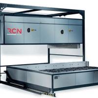
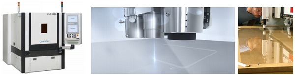
Alternatively, Corning produces a laser cutter, CLT 500X [6] which has an accuracy of less than 0.005mm (per 200mm). The laser cutter can cut pieces up to 450 x 660mm, for glass from 0.05 to 6mm in thickness. The cutting contours may be curved, straight, perpendicular or angled lines, as well as holes and slots.
Finding affordable and easily accessible tools is key for façade designers and architects exploring the potential of ultra-thin glass. This section covers three technologies: waterjet, laser and scribing. It is worth noting that the research was performed using Willow Glass, which behaves like an annealed glass product [3] and therefore can be cut without shattering in small fragments like tempered glass. It does not require further chemical tempering either, which would greatly restrict prototyping for the size and locations of baths.
1.1. Waterjet cutting
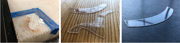
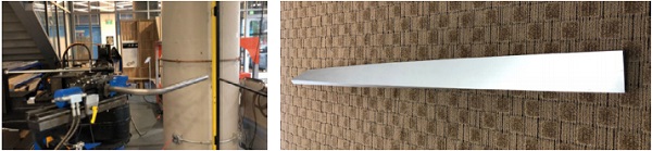
The use of a waterjet to cut glass is quite common, when glass is in the range of 2-20mm. The team tested cutting ultra-thin glass with a 5 axis CNC waterjet available at the Autodesk Technology Center in Boston, which other teams have successfully used to cut glass as little as 2mm in thickness. The waterjet fluid is purely water with a small amount of abrasive mixed in. Each trial piece was taped to a rigid plastic honeycomb structure (see Figure 7 and 8).
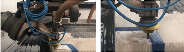
The first trial pieces were non-laminated, 0.1mm, and would either fail to cut or completely shatter. Upon lamination of two 0.1mm sheets of glass (see separate section on lamination) the trial was, in some sense successful since it didn’t completely shatter. The cutting contours were single curved and double curved (S shaped). However, the rough edge condition still wasn’t satisfactory (see Figures 9,10, 11). At this point in the project, the other cutting methods were already giving better results, so the waterjet cutting research was discontinued. Further areas of research should investigate thicker laminates of ultrathin glass, alternative interlayer materials, different abrasive mixes and densities, and other supporting materials.
1.2. Laser cutting
With the goal of developing a widely available cutting methodology, our team explored the use of tabletop laser cutters generally available in multiple architects or designers’ offices. These laser cutters are most often used to cut PET, acrylic and thin MDF boards for architectural models or signage.
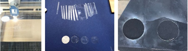
The Autodesk Technology Center in Boston has four Epilog Fusion40 CO2 120 watts Laser Cutters, with a cutting plane bed of 1000x710mm. The team successfully cut 0.1 and 0.2mm non laminated glass without shattering and we fine-tuned the following parameters to get the best the edge quality: speed, power and frequency of the laser. Plastic and steel backing materials were tested, as well as having no backing material, cutting directly on waffle support. The plastic support proved to be the best option, as it was less reflective than the steel support and leading to a better edge condition.
The absence of material did not result in a satisfactory edge condition. The best results were obtained by using a 3mm thick clear plastic backing: in fact, smoke from colored plastic would color the glass itself and be very hard to remove. Perfect flatness of the 3mm thick backing is crucial to ensure an accurate focal point of the laser. Optimum results combined a low speed, low power and high frequency laser setup. Each laser pass would remove material, as the ultra-thin glass will burn. The cutting contour width would be approximately 0.5-1mm wide with the optimum parameters. It is worth noting that laser cutters are equipped with a ventilation system which evacuates the smoke of glass and plastic.
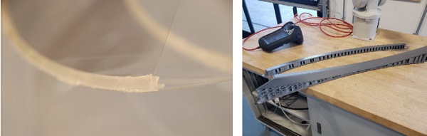
When cutting through free edges, small “ears” were observed (see Fig. 13), especially at the start of the cut at the free edge of the glass. Adding tape to secure the edges did not resolved the problem. Straight, single curved, doubly curved (S shaped) and circles were successfully testing. Good results were also observed cutting one laminated sample (see section 1.4). The team couldn’t tune the laser cutter to obtain a scored vent in order to subsequently mechanically break it.
Each laser cut specimen was submitted to a bending test (see section 1.4). Given the rough edge quality, some of the samples were polished with fine sanding paper before test. Although laser cut pieces did not perform as well as scribed pieces it is still considered a promising alley to produce cut ultra-thin glass pieces for prototyping. Future research should include laser cutting of ticker laminates, alternate interlayer materials and other support materials.
1.3. Scribing
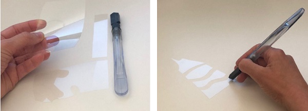
Scribing consist of scoring glass with a diamond wheel in order to create a vent, before the glass is manually broken along the vent. This technique is mastered by Coresix and was used for cutting the 0.2m glass panels of the 2017 sculpture project. Standard glass cutting wheels used for thicker glass were too rough for the ultra-thin glass and resulted in uncontrolled breakage. While procuring the adequate diamond wheel is more expensive than standard laser cutters, so far it produced the best results.
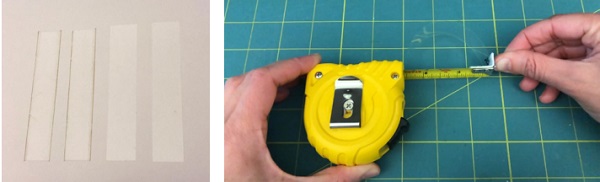
Figures 15 and 16 show manual cuts obtained using a diamond wheel. Straight, single curved, doubly curved (S shaped) and free form contours were successfully tested on a thick MDF office desk support or a stiff cutting mat. Manually handling the wheel is limited to small size samples and is not a very forgivable method as the pressure and angle of the wheel are crucial to ensure a smooth continuous cut. At the time of publication of this article, the team is exploring mounting the wheel onto a router.
Straight pieces were subjected to a bending test (see section 1.4) to compare this technique to laser cutting.
1.4. Structural Testing
Glass strength is a function of the distributions of material flaws and their propensity to grow and is primarily affected by the edge roughness. While being innovative (and quite open minded) in the process of researching accessible means to cut ultra-thin glass, the team is overly aware that glass cutting technology needs to be optimized to preserve or at least maximize the strength of glass panels. The latter is especially important since the product, here Willow Glass, has a relatively low bending strength.
As documented in [3] Corning glass specifies a design value of 40 MPa. While non weathered ultra-thin glass proved to have a safety factor of 3-4, the authors recommend using larger safety factors where ultra-thin glass is to be used for a flexible application. As a matter of fact, glass manufacturers label the “compression” surface on the glass sheets after cut, which corresponds to the surface facing the inside of the spool, whereas the exterior surface is stored in tension.
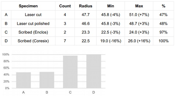
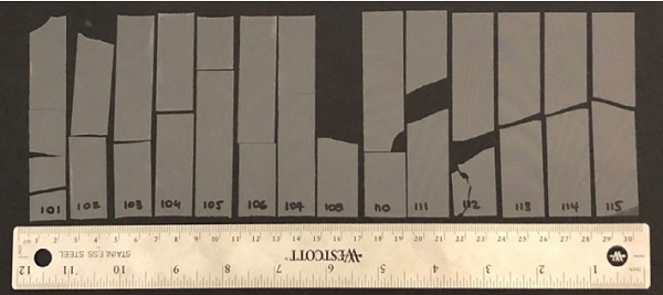
Several specimens were produced and tested, for each of the cutting methods afore mentioned. The specimen sizes were 0.1x20x100mm. All types are listed below and illustrated in Fig.17, from left to right:
A - Laser cut (4)
B - Laser cut manually sanded (3)
C - Scribed Enclos (2)
D - Scribed Coresix (7)
A total of 16 specimens were tested, which is not a significant sample population, but offers enough insights on the order of magnitude of the relative capacity of the glass elements. The samples were placed on a system that slid at one end and were fixed at the other (see figure 18).
Where necessary, a thin sheet of foam spacer was placed to avoid glass contact with metal and prevent a failure at the short edge. No specimen broke at the short edge, they all broke at approximately mid length of the long edge, as expected. Some samples experienced further breakage after slipping out of the testing support, but upon review of the videos of each test and review of the sample pieces, it was confirmed that they all broke at approximately mid length of the long edge.
The bending radius of the deformed shape (first parabolic then circular) was monitored then normalized to the index D and summarized in Fig.19 and 20. The bending capacity of samples type A was 47% of index D. Specimens of type B and C were respectively 48% and 97% of index D.
The results were relatively scattered, which might be due to multiple parameters, not isolated by the time of this publication: storage of glass and possible weathering or scratching due to handling, cutting method variability, testing setup and measurement method. While all samples for each family type were produced from one single sheet of glass each (totaling 4 source sheets total, for the 4 sample types), the distribution of flaws could vary across the surface.
While the testing setup and measurement method was the same for all samples, some minimal out of plane rotation of the support could lead to dissimilarity in the results. The results were more scattered for the series E than the other series, which can be explained by handling specific to this set, but also the fact that these samples were subject to multiple loading before tests, which could have induced fatigue in the glass flaws. Another parameter not isolated at this point is whether the samples were bent on the “compression” side or “tension” side of the product.
The edge polishing of the samples did not show a significant improvement, which remains of the order of magnitude of the measurement itself. The method of polishing, the grit grade (50), the orientation of the polishing (which is known by architectural glass designers) did not seem to soften the edge defaults produced by laser cutting. In either case, the laser cut samples were far from optimal, with a bending radius and therefore bending capacity half of those for samples C and D.
The scribed samples (C,D) were bent at radii of approx. 23mm. This value compared to the 90mm value recommended by Corning provides a safety factor of 3.9 in average, or 3.5 to 4.7 for the extreme cases. The authors do not recommend designing for less than the value recommended by Corning (90mm) as the effects of handling, weathering or stress fatigue are not quantified at this point.
In conclusion, the laser cutting methodology, while providing results half of other techniques remain a viable, consistent and affordable cutting technique for early stages of prototyping. The scribing technique, while much lesser economical provided the best results for prototyping and production. Future research should address weathering of ultrathin glass, edge treatment, stress fatigue, testing apparatus refinement, metrology.
2. Lamination
Safety glass is comprised of tempered and/or laminated glass. As previously documented [3], Willow Glass behaves like an annealed product which breaks into large shards and requires lamination. Lamination enables retention of the glass fragments, should the panel come to break. Typically, safety glass in buildings is laminated with PVB, EVA or SGP interlayer.
However, these films are much thicker than the ultra-thin glass itself, and SGP would typically be stiffer than the ultra-thin glass itself. As the context of this research is to use the flexible nature of ultra-thin glass, another thinner interlayer was investigated. We used a 1 mil (0.025mm) high quality, optically clear PET film, coated on both sides with a pressure sensitive, permanent solvent acrylic adhesive, both of which are protected by a clear PET release liner. The film and adhesive are using the finest optical clarity components and offer excellent UV stability.
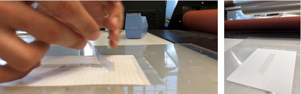
The laminated specimen size was 0.1 x 100 x 20 mm, using 2 glass specimens cut by Coresix, and one sheet of interlayer. Figures 21 and 22 depict the application of two-sided film on the glass strip at the time, before the laminate is pressed through a laminator roll at room temperature.

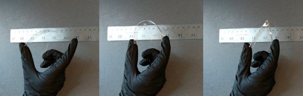
The glass laminate was manually bent (Figure 25). One lite broke at a radius close to 25mm, then the second broke shortly after. A hinge was formed at the break, the interlayer kept pieces together and no shards flew out of the glass laminate.
Whereas PET proved to be adequate to procure retention of the shards after breakage of small glass pieces, it is likely inadequate for composite action for its very low E modulus and is extremely sensitive to temperature and creeps under permanent loads.

3. Connections
The ultra-thin glass panels of the 2017 sculpture project were interconnected by means of free-form sweeping V profiles, following helicoidal curves. At that scale, the V profiles could not have been fabricated from a single strip bent in its middle, because of the crease or opening occurring along the piece. It could be fabricated out of 2 curved strips of material joined along one edge. Various fabrication options were investigated, such as CNC cutting metal sheets and welding.
Given the free-form non-repetitive geometry of the sculpture, the cutting contours couldn’t be perfectly nested and resulted in large material yield. Additionally, the strips would need to be spatially curved, either plastically or elastically which didn’t suit well the free form nature of the project. The plastic approach was disregarded because no economical technique matched the free-form nature of the geometry.
Elastic forming results in spring-back forces which would require continuous or multiple pass welds which was both timely and costly. In either case, welding could not be automatized. These aspects greatly impacted the fabrication cost and due to budget constraints, the use of metals was discarded for the sculpture project in 2017. Further explorations on metals connectors are documented below.
3D printing was deemed appropriate for the 2017 sculpture, subject to limited loads and is also appropriate for table top scale prototyping. However, at the scale of building façade systems, stainless or aluminum are definitively the strongest, most durable and optimal materials. The sweeping V profiles were 3D printed using clear PLA filament.
Time and budget constraints resulted in choosing small printers which limited the maximum size of the part to 250mm. The pieces were jointed with adhesive, creating a discontinuity in stiffness. The sculpture was built in June 2017 and stored for a few months over the summer. During that time, the adhesive parts creeped, and the connection profiles hinged at the connections, which overstressed the glass (Fig. 2). Learning from it, alternate materials and equipment were investigated.
Tthe Autodesk Technology Center in Boston has a large BigRep printer in residence, which has a 1x1x1m print bed. The team performed PLA prints trials for the pavilion project (Fig. 29). The free-form sweeping V profiles, which did not have a single flat surface, required support material during printing. Unlike several small printers, the BigRep printer does not offer a solvable support option, as the dissolution bath would need to be over 1 cubic meter. While 3D printing is a promising prototyping approach, it is worth noting that the absence of dissimilar support and print material requires intensive post-processing of the parts, which did not represent a valid fast prototyping option nor matched the pavilion project schedule.
Stemming back from the lessons learned on the sculpture, consisted in using more repetitive shapes were investigated, that nest well on a sheet. Although this drastically restricts the design, the result is much more promising and allows for automatization (Fig. 30).
4. Pavilion Design + Connections
While team Enclos performed research on cutting and laminating ultra-thin glass through the residency at the Autodesk Technology Center in Boston and capitalizing on internal knowledge and external suppliers, Josephine Stoddard wrote a thesis for the USC Building Sciences Master program on the topic: “Concepts for Working with UltraThin Glass in Elastic Bending: Typological Development and Emergent Technology”.
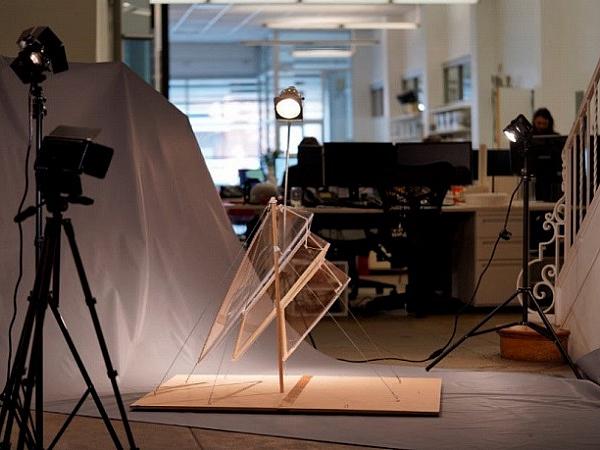
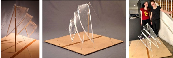
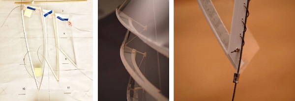
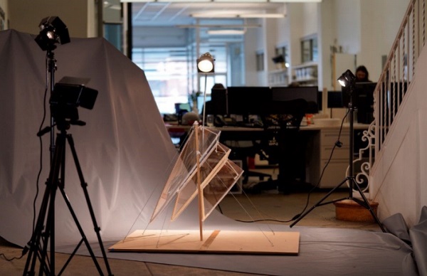
The thesis documented precedent projects, material properties, design of a pavilion with bending active ultra-thin glass, numerical analysis of the ultra-thin glass pavilion structure and the elaboration of a physical scaled model. The scaled model was made of PET sheets, 3D printed connectors, wood mast and stainless cables connected to a stiff MDF platform. It was 850mm tall and 1200x1200mm wide (Fig. 31,32,33).
Whereas some steps capitalized on the development of the 2017 sculpture, such as geometry rationalization principals or most of the connections, the pavilion design also carved several innovative ideas. The designer was keen on reusing tensile architecture typology and elements, where glass panels would wrap around a central mast, stabilized by cables, like multiple boat sails.
While connections between glass ribs would be detailed as sweeping V’s like in the sculpture, the design used channels to reinforce straight edges. These straight edges profiles were introduced not only to connect the glass edge to the tension cables in order to limit the glass edge deflections but also to protect naked edges from the public which would be able to walk around the full-scale pavilion. The straight edge pieces would run along the tension cable and connect to it with a spiraling secondary rigging (Fig. 36).
The PET was cold bent on the 3D printed supports and adhered with hot glue gun. The subparts were jointed to one another in a large preassembly (Fig.34). The sails assembly was subsequently propped off the tension cable by a small truss (Fig.35). Ultimately, the tension in the cables was adjusted and the cables locked.
Not only did this research propose innovative detailing ideas, not all reflected in the pavilion project, but it also well documented the strenuous iterative design process and prototyping process as it impacts the scale of the model and project schedule.
Conclusion and future works
The present research was approached on two aspects: manufacturing and design, as these are inextricable.
This article demonstrates that low cost tools, accessible to a large pool of students and design professionals, are available for the prototyping of ultra-thin glass elements. While professional waterjet and industrial laser cutting equipment are not accessible to all designers, two viable techniques are proposed: table-top laser cutting and manual scribing with a diamond wheel. At this point, the manual scribing gave the best immediate results but is hard to scale up, even for prototyping table-top models. Multiple findings on lamination and connections have been presented, providing guidance for economical prototyping.
As for the design, the 2017 sculpture project set forth a concept for design and analysis. The 2018-2019 USC Master thesis provided an excellent documentation for the current state of the research, and a successful demonstration that a very determined Building Science student from the USC Architecture School, with limited structural engineering or glass knowledge can yet become a local expert in designing with ultra-thin glass.
The research identified plethora of further ultra-thin glass research topics: weathering, edge treatment, stress fatigue, testing apparatus refinement, metrology, etc. Other topics to be addressed are connections, structural, chemical and thermal compatibility of adhesives, numerical analysis, glare and optics. These topics are sine qua non for the implementation of ultra-thin glass in the build environment.
Ultra-thin glass has a great potential in the build environment for its light weight, durability and its optical quality. Yet there are still many outstanding questions to be answered regarding the detailing and scalability of ultra-thin glass panels. The authors hope that sharing their prototyping ideas will inspire other designers to explore designing and prototyping with ultra-thin glass.
Acknowledgements
The authors are grateful to Enclos for the research and development funding, design and manufacturing input, rendering images. USC Master Student Josephine Stoddard was essential to keep the ultra-thin design research alive and well documented. The Autodesk Technology Center Boston's staff and neighboring residents offered time and equipment to support this research (eg. Lumi inc for the laminator and BigRep 3D printer).
Conflict of interest statement
On behalf of all the authors, the corresponding author states that there is no conflict of interest.
References
[1] https://www.us.schott.com/advanced_optics/english/capabilities/down-draw-process.html (accessed 4/30/2019)
[2] https://www.cmog.org/article/long-road-successfusion-draw-glass (accessed 4/30/2019)
[3] Shaping ultra-thin glass, Pennetier, Bowers, Evain, GPD 2017
[4] Concepts for Working with Ultra-Thin Glass in Elastic Bending: Typological Development and Emergent Technology, Josephine Stoddard, University of Southern California school of Architecture, 2019
[5] https://coresix.com/services/cutting (accessed 4/30/2019)
[6] https://www.corning.com/worldwide/en/products/advanced-optics/product-materials/lasertechnologies/clt-500x.html (accessed 4/30/2019)