The Paper with a title "Vacuum Insulated Glazing under the Influence of a Thermal Load" was first presented at GPD 2017 by Dr. Antti Aronen and Dr. Cenk Kocer, University of Sydney.
Typically, solder glass is used as the edge seal, which results in a narrow rigid bond between the glass panes. In-service, the VIG unit must withstand forces resulting from atmospheric pressure, and also survive temperature differences (thermal loads) that occur in extreme climates. In this paper a study of the finite element analysis of the deformations and stresses induced because of a thermal load are presented.
The finite element model was validated with respect to measurements. Using the finite element model, results of the dependence of the thermally-induced stresses on the size of the VIG unit, the thickness of the glass panes, and the temperature field over the surfaces of the glass panes due to different heat transfer coefficients and thermal conductance of a VIG, are presented and discussed.
1 Introduction
Vacuum Insulated Glazing (VIG), shown in Fig. 1, is a highly insulating double pane glazing, with its edges sealed hermetically using solder glass (a glass frit), and containing a thermally insulating internal vacuum. Typically the width of the edge seal is about 4-8 mm. Within the internal vacuum, between the glass panes, an array of small spacers is used to maintain the separation of the glass panes under the action of atmospheric pressure.
Nevertheless, atmospheric pressure does cause local bending, and thus stresses, in the glass panes around and in between the spacers and close to the edge seal [1,2]. Additional stress in the VIG is induced by other external loads, including wind, impact and temperature differences.
![Fig. 1 An illustration of the Vacuum Insulated Glazing [3]](/sites/default/files/inline-images/Fig1_75.jpg)
When under load the rigid solder glass edge seal prevents relative movement of the glass panes close to the edge seal. In particular, under a thermal load the differential expansion of the glass panes induces a moment of rotation which leads to mechanical stresses in the glass, and overall bending of the VIG panel. The amount of stress induced and the degree of bending in the VIG unit is highly dependent on several factors related to heat transfer properties, size parameters and the mechanical properties of the individual components.
The purpose of this work is to present a finite element analysis which will accurately describe the deformations and stresses that are induced because of a thermal load on a VIG. In the following section a review of the background work is presented. Following this, the validation of the thermo-mechanical finite element model with respect to measurement data is presented.
Finally, the finite element model is solved to determine the influence of the size of the VIG unit, the thickness of the glass panes, and the temperature field over the surfaces of the glass panes due to different heat transfer coefficients and thermal conductance of the VIG, on the deformations and thermallyinduced stresses in the VIG unit.
1.1 Previous work
The thermal bending of a solid plate, in which the temperature is non-uniform through its thickness, has been studied extensively [4,5]. However, such work cannot be directly applied to the VIG case since the VIG is not a homogeneous monolithic plate. Specifically, the temperature profile through the thickness of the VIG structure is quite different and lateral heat flow in the vicinity of the edge seal results in lateral temperature variations inthe-plane of the VIG glass panes.
The overall bending and resulting stresses in the VIG due to a thermal load have been studied. Collins et al. [6] and FischerCripps [7] reported analytical solutions for the structural deformations and stresses induced in a VIG based on the theory of bimetallic beams; theory originally developed by Timoshenko [8]. The finite element method was used in studies by Simko et al. [9], Wang et al. [10], Wullschleger et al. [11] and Fischer-Cripps [7] to study thermal load effects.
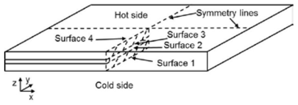
The Simko et al. [9] study also presented measurement results for overall bending and the mechanical strain in VIG units under well-defined thermal conditions. All of these studies have shown that the thermally induced stresses in each glass pane of a VIG unit vary through the thickness of the panes. The surface labeling to be referred to in the following discussion is defined in Fig. 2.
For a VIG with an un-supported edge condition, the stresses remote from the edge seal over the outer surfaces of the hot side (surface 4) and cold side (surface 1) are found to be isotropic and of the same magnitude, but are tensile and compressive, respectively [1,6,7,9]. Closer to the edges of the glass panes, the stresses over the glass surfaces are anisotropic.
The stresses normal to the edges approach zero near the edge, while the stresses parallel to the edge are approximately twice in magnitude than that found at the center of the glass panes; this is due to lateral temperature variations in the glass panes close the glass edge. On the inner surface of each glass pane (surfaces 2 and 3 for the cold and hot pane, respectively) the magnitude of the stress at the center is about twice that of the stress on the outer surface of the same pane and of opposite sign (that is, tensile and compressive, respectively); where the stress through the thickness of each pane varies linearly.
It is well known that the rate of crack growth in glass, particularly soda-lime float glass, is highly dependent on the relative humidity of the surrounding environment to which the stressed crack tip is exposed [12]. Since the internal surfaces (surface 2 and 3) of the VIG are exposed to the vacuum cavity, for an equal magnitude and distribution of stress the probability of crack initiation at surfaces 1 and 4 would be significantly higher than that on surfaces 2 and 3. In addition, in all thermal load cases solved in this work, surface 4 will have the greater tensile stress field. Therefore, in this work, as a matter of brevity, only the stress field induced over surface 4 is considered.
2 Results
The Finite Element Method (FEM) is used to simulate the thermal and mechanical behavior of the VIG under applied loads. The thermal model is a static model used to solve the temperature distribution over the VIG unit. In the model the spacers are modeled with all relevant material and contact properties included.
Furthermore, surface-to-surface radiative heat transfer within the vacuum cavity and the temperature non-uniformity over the glass surfaces were included. On the outer surfaces of the VIG, convective boundary conditions are employed to simulate the heat transfer process between the inside/outside environment and the glass hot/cold surfaces, respectively.
In all cases the FEM solutions are performed with the initial step to determine the deformation/stress field due to atmospheric pressure only and then, in a subsequent second step, the total solution of atmospheric pressure plus the desired thermal load is solved. The thermal load solution is obtained by simulating the temperature distribution over the VIG unit first, and subsequently the mechanical strain over the VIG unit due to the thermal load is calculated.
Since the temperature range of interest is not large, the mechanical solution is obtained for linear elastic behavior of the glass and spacers. The stress distribution over the VIG due only to the thermal load is calculated by subtracting the stress distribution due solely to atmospheric pressure from the final data of atmospheric pressure plus thermal load. As a matter of brevity the mechanical behavior is solved in this paper only for the case of an un-supported (unconstrained or free) edge support.
Therefore, to constrain the model from virtual full-body displacements, only the corner points (FEM model nodes) of the VIG model are fixed not to move in the z direction, only on surface 1 (cold side). To minimize the computational effort/time required to obtain a solution, the mirror symmetry planes are used to reduce the required model size to one quarter of the original full size VIG unit; along the symmetry lines appropriate boundary conditions are applied, Fig. 2 highlights these symmetry planes.
In all cases the finite element software package ANSYS version 17.0 was used to simulate thermal and mechanical behavior. In the following sections the FEM results are validated through direct comparison to measurements published by Simko et al. [9]. Following this, the typical stress and deformation results from the thermal load simulations are presented. This includes data of the effect of different VIG model parameters on the stresses and deformations.
2.1 Validation of the finite element model with respect to measurements
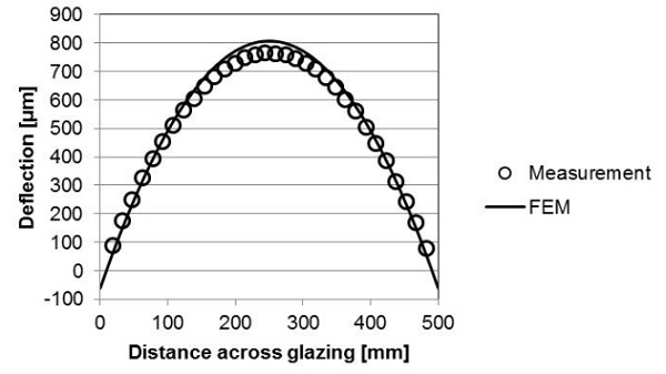
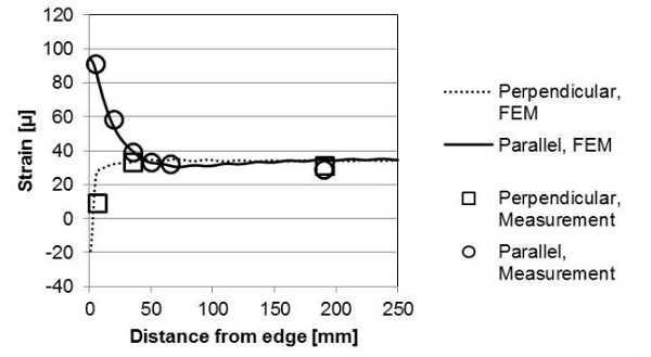
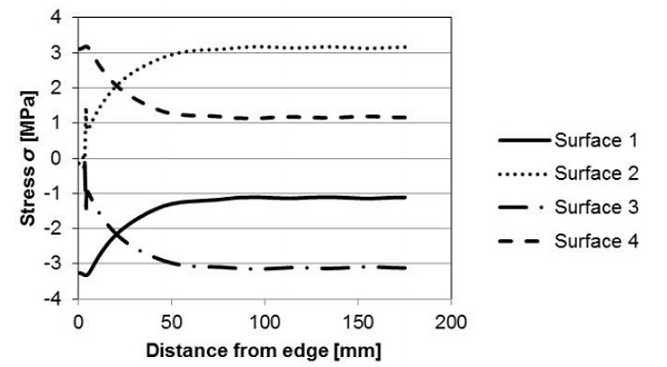
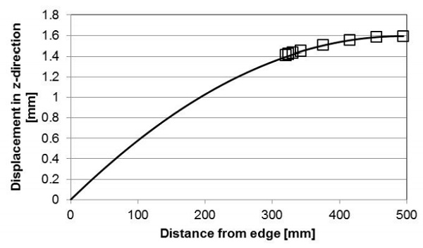
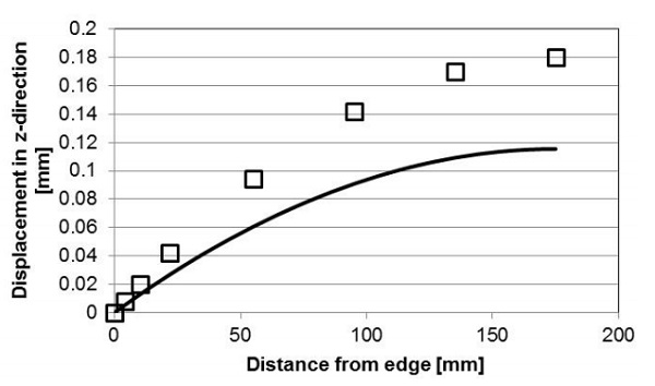
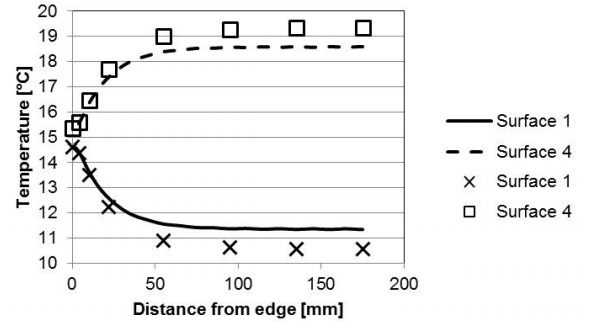
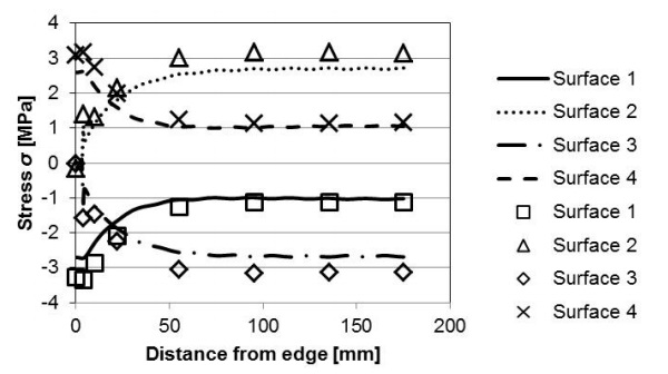
The results from the FEM are validated by direct comparison to measurement data. The overall bending and the mechanical strain (perpendicular and parallel to the edge) at different locations along a mirror symmetry line on the hot side (surface 4) of a VIG are presented in Fig. 3 and 4, respectively. The FEM simulations were performed using model parameters taken from the Simko et al. [9] work and are listed in Table 1.
![Table 1. The material properties of soda-lime glass and the dimensions of a VIG unit, as used by Simko et al. [9], and as used in this work.](/sites/default/files/inline-images/Tab1_34.jpg)
The FEM simulation and measurement data in Figs. 3 and 4 are in good agreement. The center deflection of the VIG from the FEM simulation is approximately 5 % higher as compared to the measured displacement. This is due mainly to the small difference in curvature close to the edge of the VIG unit. The specific edge constraints of the real VIG measurement setup cannot be exactly reproduced within the finite element model.
2.2 Behavior of VIG under thermal load
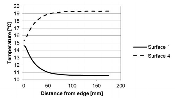
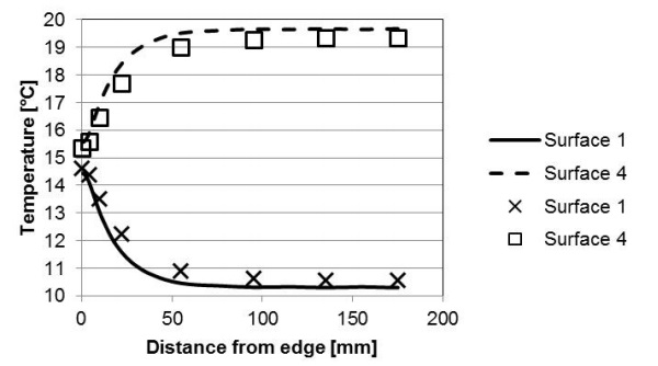
In the previous section, FEM and measurement data were shown to be in good agreement over the glass outer surface on the hot side (surface 4). In this section the FEM simulation results of the stresses and temperature field on a VIG (over different surfaces) are presented, where the model parameters (reference case) are listed in Table 1. First, the temperature profile along the mirror symmetry line is shown in Fig. 5.
The temperature at the center of the VIG is dependent on the glass-to-glass thermal conductance of the VIG, the external heat transfer coefficients and the external inside/outside temperatures. Close to the edge the temperature changes exponentially from the temperature at the edge seal, to the temperature on the glass surface at the center of the glass pane. Even though the edge seal region is a thermal bridge the hot and cold side (surface 4 and 1, respectively) surface temperatures over the edge seal are not equal. There is a small temperature difference (approximately 0.5°C in Fig. 5) and therefore, a through thickness temperature profile at the edge seal.
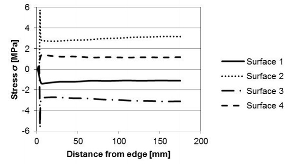
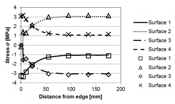
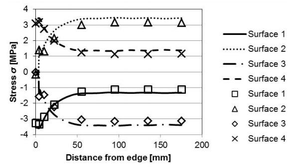
The stress profile over each surface, parallel to the edge, is shown in Fig. 6. The stress profile at the edge is close to three times the magnitude of the stress remote from the edge (on surfaces 4 and 1), which was also the case as shown in Fig. 4. The stress remote from the edge on the inner surfaces is also close to three times the magnitude as compared to the stress remote from the edge on the outer surfaces. This result does not agree with the previous published analytical results [1] discussed in section 1.1.
In the published works the analytical solutions were obtained on the assumption that each glass pane is wholly at a defined constant temperature. The FEM stress field perpendicular to the edge, Fig. 7, is much more uniform along the symmetry line of the VIG unit than the stress parallel to the edge, Fig. 6. In Fig. 7, there is a significant spike in the magnitude of the stress close to the edge, at the inner surface.
The spike in stress is wholly caused by a numerical singularity at the model node which is the point at which the glass pane and the rigid edge join together. In a “real” VIG unit the transition from the glass pane to the edge seal is smooth and there is no significant spike in stress, therefore, the spike in stress in Fig. 7 can be ignored.
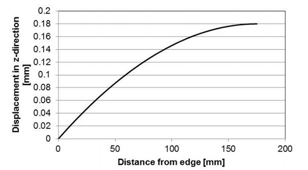
The deflection of the VIG unit along the symmetry line calculated using FEM is shown in Fig. 8. The deflection at any point along the surface of the VIG unit, relative to the maximum deflection at the center of the unit, is proportional to the square of the distance from the center.
2.3 Case study using the Finite Element Method
Clearly, there are numerous parameters which affect the thermal and mechanical response of the VIG unit. In the following sections the results of FEM calculations looking into the effects of VIG unit size, glass pane thickness, overall thermal conductance, and external heat transfer coefficients, are presented. The parameters employed in these calculations are listed in Table 1 as the reference case. In the following discussion the stress distribution parallel to the edge seal is most relevant to the potential fracture of the glass panes, and thus, only the results of the stress field over surface 4 and close to the edge seal are considered.
2.3.1 Effect of unit size
From the thermo-mechanical FEM simulations it was found that the VIG unit size has two effects on the distribution of stress. The first effect is due to changes in the temperature distribution over the VIG and the second is due to the non-linear effect of bending. Fig. 9 is a plot of the stress profile, along the symmetry line from the edge seal to the center-ofpane, for two unit sizes of 350 x 350 mm2 and 990 x 990 mm2.
As the unit size is reduced from 990 x 990 mm2, the temperature nonuniformity associated with heat flow through the edge seal occurs over a larger proportion of the surface area of the VIG unit. This decreases the average temperature difference between the glass panes, and correspondingly reduces the stresses at the outer surface (surface 4).
Clearly, however, for larger unit sizes the maximum center deflection is larger, see Fig. 10, and thus, for the larger unit size the non-linear deformation of the plate must be taken into consideration. The effect of a non-linear deformation is discussed in greater detail by Wullschlegger et al. [11]. It is found that the non-linear effect produces an increase in stress at the center of the unit, and a decrease in stress close to the unit edge.
The deflection of the VIG unit, Fig. 10, is proportional to the square of the characteristic dimension of the sample if the curvature is constant; therefore, the maximum deflection of the VIG unit increases dramatically with increases in the unit size of the VIG. In order to directly compare the curvature of the deflected small and large unit, the data of the small unit, in Fig. 10, is shifted so as to make the center deflection of the small and large unit the same. Interestingly, the overall curvature of small and large VIG units is the same. The maximum center deflections of the large and small VIG units are 1.6 and 0.2 mm, respectively.
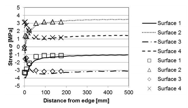
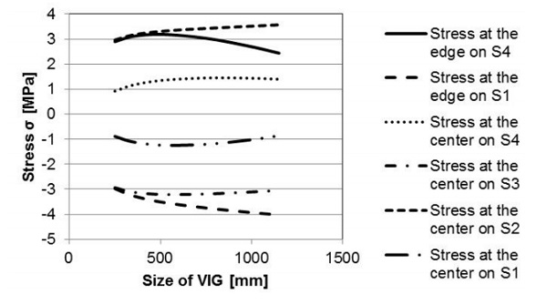
Fig. 11 is a plot of the stresses as a function of the characteristic length of a VIG unit. In the figure are shown the stresses parallel to the edge seal, at the edge, on the outer surfaces and at the center of all surfaces. The magnitude of the stress increases until the characteristic length reaches 500 mm. This is due to the influence of the lateral temperature profile of the edge region. At a length greater than 500 mm the lateral temperature distribution decreases and the effect of nonlinear deformation dominates.
At the edge the non-linear deformation results in a lower stress parallel to edge, with an increased stress remote from the edge. Due to the inplane temperature distribution and the nonlinear deformation the peak tensile stress at the edge on the outer surface of the hot pane (surface 4) occurs at a length of approximately 500 mm. It is important to note that the unit length at which the stress peaks is dependent on the external heat transfer coefficients and the thickness of the glass panes.
2.3.2 Effect of glass pane thickness
Fig. 12 compares the stress profile over the mirror symmetry line, from the edge seal to the center of glazing, for VIG units with either 4 or 6 mm thick glass panes, equal on both sides. The resulting deflection of the VIG unit is shown in Fig. 13. Clearly, the stress profiles over each surface do not change significantly relative to a change in the glass pane thickness. However, the overall deflection (bending) of the VIG unit is appreciably less for thicker glass panes, as would be expected.
2.4.3 Effect of the glass-to-glass, center-ofglazing, VIG thermal conductance (U-value)
The ultimate heat flow through a VIG unit will, clearly, be highly dependent on the U-value of the unit. Figs. 14 and 15 compare the temperature and stress profiles in VIG units where the U-values are 0.47 W m-2 K-1 and 1.38 W m-2 K-1. The latter U-value is for a VIG with a 20 mm spacer array separation and a single internal low-E coating (0.03 hemispherical emittance). Due to the higher Uvalue the temperature difference between the hot and cold panes is less. This reduced temperature difference proportionally reduces the magnitude of induced stress; where a similar change is observed when the external temperatures are changed.
2.3.4 Effect of external heat transfer coefficients
Clearly, the magnitude of the external heat transfer coefficients defines the surface temperatures of the glass panes, and therefore, the induced stresses within the VIG unit. This is best illustrated in Figs. 16 and 17 where the VIG glass-to-glass U-value is 0.47 W m-2 K-1. In each case, the external heat transfer coefficients were 8 W m-2 K-1 and 15 W m-2 K-1, and equal on both sides of the VIG.
The external heat transfer coefficient has a nonlinear effect on the temperature and stress distributions because of its influence on the lateral heat flow through the glass panes. Increasing the external heat transfer coefficient increases the temperature difference between the glass panes at the center region of the VIG. Furthermore, the in-plane temperature profile at the edge region now extends from the edge to center region temperature over a shorter distance, and thus, the relative local temperature difference change close to the edge is larger as compared to that at the center-of-pane region.
3 Summary
In this paper the finite element method was employed to determine the deflections and stresses in a VIG unit which is subjected to a thermal load. The FEM gives results that are in good agreement with measurement data published in the literature.
Specifically, the stress distribution found on each glass surface clearly highlights the effect of the whole area influence of the convection boundary condition of heat transfer used in the simulations. Over the outer surface (surface 1 and 4) the stress parallel to edge at the edge region is about three times the stress remote from the edge.
It was also found that the magnitude of stress over the inner surface (on surface 2 and 3) remote from the edge is about three times the stress over the outer surface (on surface 1 and 4). The parameter study shows clearly that:
- Increasing the VIG unit size increases the magnitude of the stress until the effect of non-linear deformation dominates. Then the stress at the edge region decreases and at the center it increases,
- Change in the glass thickness in the VIG only affects the bending of the unit, since it does not affect the temperature distribution,
- Change in the external heat transfer coefficients, and also the unit glass-toglass U-value, results in a change of the temperature profiles on the VIG. The increase in the glass-to-glass U-value decreases the temperature difference between the glass panes, which results in lower stresses,
- The external heat transfer also has a nonlinear effect on the stress and temperature distributions.
Acknowledgements
The writers thank Richard Collins for valuable comments on the manuscript. The authors also acknowledge the University of Sydney HPC service at The University of Sydney for providing HPC and software resources that have contributed to the research results reported within this paper.
References
[1] Fischer-Cripps, A.C., Collins, R.E., Turner, G.M., Bezzel, E.: Stresses and Fracture Probability in Evacuated Glazing. Build. Environ. 30(1), 41-59 (1995).
[2] Collins, R.E., Turner, G.M., Fischer-Cripps, A.C.,Tang, J.-Z., Simko, T.M., Dey, C.J., Clugston, D.A., Zhang, Q.-C., Garrison, J.D.: Vacuum Glazing – A New Component for Insulating Windows. Build. Environ. 30(4), 459-492 (1995).
[3] Kocer, C.: A discussion of highly insulating windows; a hybrid vacuum insulating glazing. In: Glass Performance Days 2013, Glaston, Finland, 447-450 (2013)
[4] Hetnarski, R.B., Eslami, M.R.: Thermal Stresses – Advanced Theory and Applications. Springer (2009) [5] Boley, B.A., Weiner, J.H.: Theory of Thermal Stresses. Dover Publications (2012)
[6] Collins, R.E., Fischer-Cripps, A.C., Tang, J.-Z.: Transparent Evacuated Insulation. Sol. Energy 49(5), 333-350 (1992).
[7] Fischer-Cripps, A.C.: Stresses and Fracture Probability in Evacuated Glazing. Dissertation, The University of Sydney, Australia (1993)
[8] Timoshenko, S.: Analysis of Bi-Metal Thermostats. J. Opt. Soc. Am. 11(3), 235-255 (1925).
[9] Simko, T.M., Fischer-Cripps, A.C., Collins, R.E.: Temperature-Induced Stresses in Vacuum Glazing: Modelling and Experimental Validation. Sol. Energy 63(1), 1-21 (1998).
[10] Wang, J., Eames, P.C., Zhao, J.F., Hyde, T., Fang, Y.: Stresses in Vacuum Glazing Fabricated at Low Temperature. Sol. Energ. Mat. Sol. C. 91, 290-303 (2007).
[11] Wullschleger, L., Manz, H., Ghazi Wakili, K.: Finite Element Analysis of Temperature-Induced deflection of Vacuum Glazing. Constr. Build. Mater. 23(3), 1378-1388 (2009).
[12] Lawn, B.: Fracture of Brittle Solids. 4th Ed. Cambridge University Press, Great Britain (1993)