First presented at GPD 2019
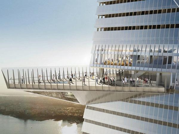
This paper presents a case study of three glass structures with varying challenges on the Observation Deck of Hudson Yards in New York – a 3m, cantilevered Windscreen subject to wind gusts of up to 4.7 kPa, an outdoor Glass Floor with high traffic, and a combination glass floor and window structure.
In this paper, we look at the challenges of laminated connections, ensuring structural safety and performance, meeting a clear architectural vision, and installing glass to high tolerances with access from one side at 335m height.
Project Overview
Hudson Yards is a $25bn mixed real estate development in the heart of New York City. The development is the most expensive private real estate development in US history and comprises a platform over a working rail yard, and 16 buildings on the platform. The tallest of these buildings, at 386m, is 30 Hudson Yards. There is another superlative associated with this skyscraper, and that is that it has the highest (335m) outdoor observation deck in the Western Hemisphere.
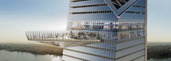
Schlaich Bergermann Partner was hired by Related Hudson Yards, as the façade engineers for the specialty facades on 30 Hudson Yards. KPF is the architect for both the Hudson Yards master plan and 30 Hudson Yards. The specialty facades include the observation deck secondary structure and cladding, and the subjects of this paper – the three structural glass projects on the observation deck. These three structures are the Windscreen, Terrace Glass Floor and Hull Window. According to a review by the Wall Street Journal, the observation deck “offers the most spectacular vista of any building in America.”
The key to achieving these views was through the aforementioned glass structures, which are simultaneously both physical barriers and visual connections.
The Three Glass Structures
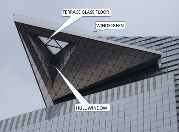
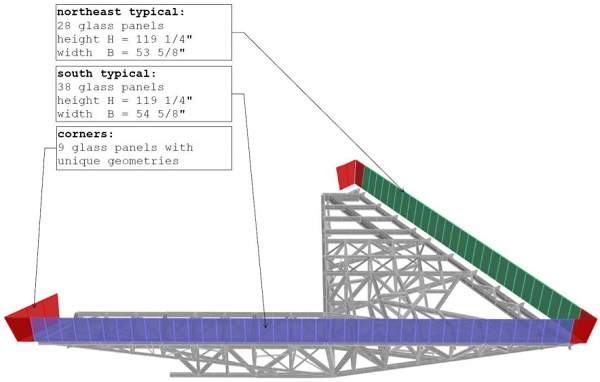
The Windscreen is a 3m high cantilever, sloped at 9° from the vertical. This forms the transparent perimeter of the observation deck and lessens the impact of wind gusts on pedestrians. The glass is supported in a stiff, galvanized steel moment shoe.
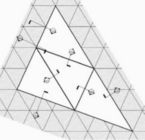
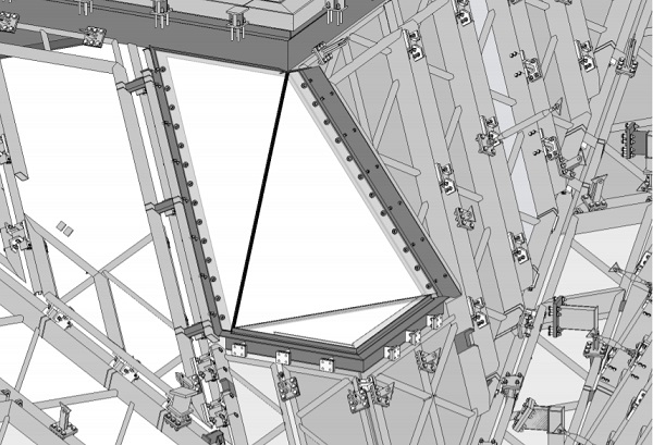
The Terrace Glass Floor offers unobstructed views to the cityscape below and is composed of a set of four repeating glass triangles. Stainless steel beams support both the glass above and the obscured façade maintenance rails which hang below. The stainless steel beams connect into a perimeter framing of mild steel, which itself connects to the primary structure of the observation deck.
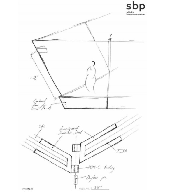
The Hull Window offers similar views to the Terrace Glass Floor, but from an interior space. Three independent panels – a glass floor and two sloping triangular panes – form a faceted shape.
The two sloping panels are supported at far edges. This means that no additional dead loads act on the glass floor panel, and the vertical panels do not produce a constant shear load on the adjoining panel from their dead loads. Supporting these panels at their far edges also allows for a minimal joint at the interfaces.
Boundary Conditions
As unique structures in a unique space, the Windscreen, Terrace Glass Floor and Hull Window also have peculiar requirements. As with all glass structures, it is essential to think about redundancy, especially at 335m high.
Similarly, access for installation, maintenance, and replacement must inform the design. Due to the expected high pedestrian traffic and the large wind loads at this elevation, the structures also experience high loading. These aspects all played a role in the design.
Loading
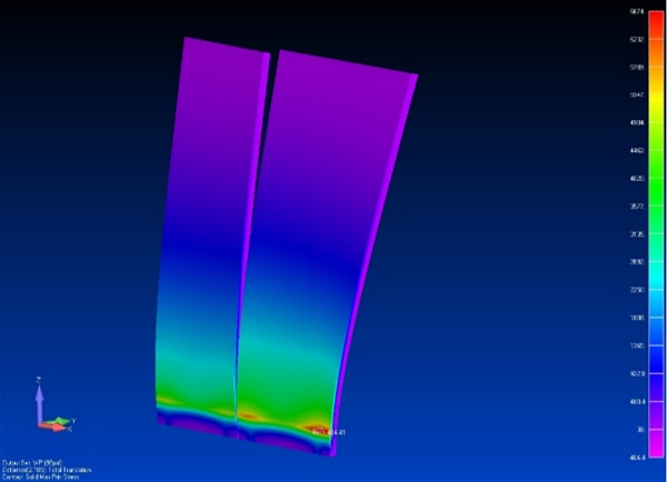
One of the primary functions of the Windscreen is to form a barrier to resist the high wind loads, which exist at this height. As such, it is estimated to be exposed to 4.7 kPa wind pressures and 3.4 kPa wind suction. As a 3m glass cantilever with high loading, it is crucial to control deflection and ensure a robust design.
Both the Terrace Glass Floor and Hull Window were designed for 4.8 kPa uniform live loads on the horizontal surfaces and for 1.3 kN concentrated live loads over 50x50mm areas, in keeping with the requirements of ASCE 7-05 and New York Building Code.
Access
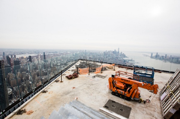
The observation deck was constructed in a modular system, with modules up to 35,000 kg assembled in Italy, shipped to New York, craned up to 335m and installed together on site. Once the structure of the observation deck was in place, there would be no raft or installation platform in place to allow access to both sides of the Windscreen.
Therefore, all access for installation, replacement and maintenance was required to be performed with access from the terrace and a limited access from the exterior using the façade maintenance machines. As a signature element of the building, it was essential that it would be possible for future contractors to be able to install the structure to a high degree of tolerance. The possibility of damage to exposed edges and coatings means that replacement of panels must be accounted for.
With these in mind, sbp devised installation and replacement narratives to ensure each step was thought through in the design stage. The Terrace Glass Floor has access on all sides and is almost horizontal, with only a minimal slope for drainage assumed. Therefore, there are not the same difficulties with installation as with the other structures. However, the footfall expected on the upper surface means that the surface treatment is likely to become worn away after continuous use. The microfractures initiated and propagated by scratches on the surface of glass lead to compromising the compression layer of heat-treated glass and eventual fracture of that layer. If the top layer is damaged in a multi-layer laminate, the entire laminate must be replaced.
At an early stage in design, the idea of a removable layer or laminate was explored. This idea is in use in some interior glass floors but was not appropriate for this project. It was not pursued due to several reasons:
• The difficulty of forming a hermetic seal (for load transfer) on site during replacement
• Increased deflections
• Monolithic layers are less safe and not structurally sufficient for wind suction and concentrated live loads
The Hull Window had similar design parameters to the Windscreen, in that access was only possible from the interior. The sequence was determined to be that the hung panels would be installed first since they would need space to be rotated into place in a limited interior space. After these were installed, the glass floor would complete the structure and the structure would be sealed.
Transparency is key for all these structures, and so regular cleaning is expected. Titanium based self-cleaning coatings were not used due to the possibility of degradation of these over the glass lifetime, and the need to use exterior surfaces for different coating products.
Tolerances and Adjustments
The alignment of the large, sloped glass surfaces of the Windscreen with only one side available for access is a challenge for installers. Therefore, a high degree of adjustability was required from the design. Up to 25mm variance in all directions was expected from the erected primary steel structure which supports the Windscreen.
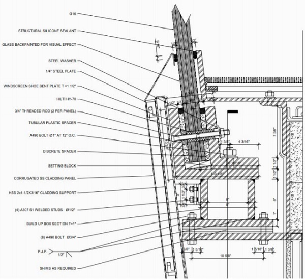
Vertical and horizontal adjustment are provided by shims and slotted holes in the plate below the box element, respectively. Setting blocks inside the shoe allow for minor adjustment.
Codes
It is a common issue for designers of structural glass that codes may be lacking instruction and so structures must be designed from first principles. ASTM E1300 does not require for redundancy layers in vertical glass such as the Windscreen. However, based on prior experience and the precarious site location, the glass make-up was designed to withstand ULS loads with one layer broken.
Following ASTM E2751, the exterior and interior glass floors were also designed to be structurally sound if one layer broke. Due to the inevitable surface scratches and microfractures from users, the top layer was also not considered as a structural layer. However, deflections, and not stresses, were controlling for these glass build-ups.
Architectural Intent
The architectural intents for the structures informed how the glass make-ups were prescribed. Maximum transparency was the aim for all elements, and so Low-Iron glass was specified. SGP was chosen as the interlayer material for reasons including:
• Lack of reactivity to UV light and water
• Lowered risk of delamination
• High level of shear transfer between glass layers, allowing for thinner makeups
• Post-breakage retention
It was decided at an early stage that an antireflective coating would be applied to the Windscreen. For best performance, both exterior faces of the laminate were to be coated.
Considering that the terrace glass floor would be exposed to rain, the surface needed to be slip resistant to protect the safety of users. US codes are not prescriptive in this area, with many different possible tests and standards, most leading to the conclusion that the owner must choose in the final configuration. Different anti-slip products were reviewed, such as laser etched, acid etched and fritted. These were rated on factors such as durability, transparency and level of slip resistance. A fritted surface was eventually chosen.
Samples were reviewed based on certain characteristics:
• Transparency of glass
• Edge work
• Quality of coatings
Structural Systems
Below the level of the terrace floor slab is the base support for the windscreen. Since the Windscreen will be subjected to high wind loading, the supporting shoe was designed to be as stiff as is feasible in the space. Due to the need for a thick, stiff shoe, galvanized mild steel was chosen over the materials that could be used for a smaller balustrade, such as stainless steel or aluminum. The supporting structure was designed to minimize rotation since any rotation in the shoe is magnified at the top of the glass.
Between the 40mm thick steel and the glass, Hilti HY-70 was prescribed. This material allows for transfer of compressive forces from the glass to the shoe and does not form a chemical bond with the glass surface.
Choosing a cementitious grout allows for the easier removal in the case of replacement. Since the exterior face of the Windscreen is difficult to access, this material fits the site conditions.
Two bolts through the glass stabilize the panels for in-plane loading and act as an extra method of redundancy.
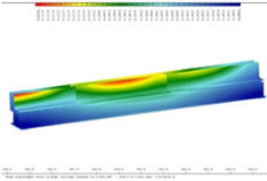
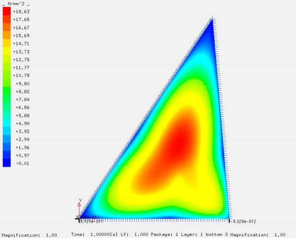
The full system, including glass layers and interlayers, was analyzed using brick elements in Nastran. The glass make-up is 12-15-15-12 FT
To preserve the experience of a flat surface and to avoid possible ponding of the panels in the glass floors of both the terrace and Hull Window, L/360 was chosen as the deflection limit. This was the controlling aspect in prescribing the make-ups.
Windscreen Connections
The vertical gaps between adjacent Windscreen panels was set at 25mm. This figure was chosen to protect the safety of building users and to lessen the possibility of objects falling to the street below. However, under SLS cases of wind pressure, free corner panels could move more than this amount. To avoid a clash of panels under wind loading, sbp designed connections between adjacent corner panels to reduce differential deflection.
Early design options were presented to the architect and client, with the aim of connecting panels in a structurally efficient and elegant manner.
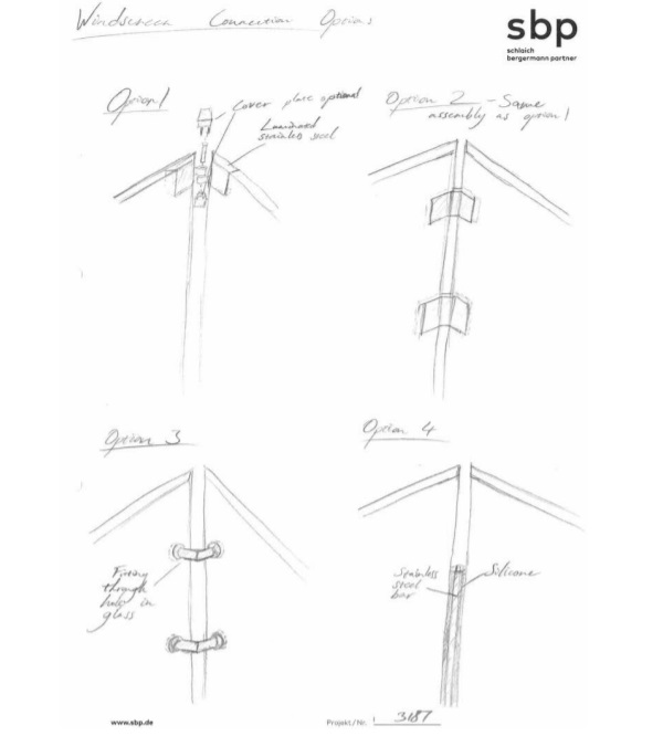
A variation of Options 1 and 2 was chosen for the main SE corner, while Option 4 was chosen for the other corners. Although the first sketch for Option 1 showed a vertical pin, this was rotated 90° in later evolutions of the design to allow for easier installation.
The observation deck, now named The Edge, is expected to open to the public in 2020.


 demonstrator at Glass Technology Live during Glasstec 2024 (© Cas Maertens).")