
1. Introduction
Glass selection represents one of the core aspects in decision-making process and planning of glass curtain walls for architects, engineers, and clients among others. Wide variety of advanced coatings and surface treatments along with innovative smart glazing technologies such as switchable glazing and solar control systems offer a multitude of options for reaching design and performance goals.
This brings a challenge to architects and engineers to choose between two opposing criteria, energy performance and clear vision. While engineers rely on very accurate and consistent analytical and numerical tools for their optical and thermal performance analyses, visualization of selected glazing systems by architects and visualizers depend on subjective estimates of glass properties, producing very inconsistent and often misleading results.
Therefore, for qualitative analyses of glass, initial glazing selection has been traditionally based on small glass samples, later verified through full-scale facade visual mockups. Besides being very costly and timely, this process also imposes limits for reaching design vision by drastically reducing the palette of options and design iterations.
Alternatively, computergenerated images offer limitless options and high flexibility with a fraction of time and cost compared to the physical mock-ups. Therefore, this paper proposes a generalized, physicallybased virtual prototyping approach for a flexible glass design and communication that minimizes discrepancies between virtual and physical prototypes.
2. Previous works
Physically-accurate visualizations of glazing in the past were predominantly based on validated Radiance simulations using the rpict module [1]. However, Radiance relies on simplifications such as the single surface representation of glass that lacks multiple reflections and optical distortion at higher incidence angles caused by multiple glass panes in Insulating Glazing Units (IGU).
Moreover, IGUs may include laminated glass panes as well as different coatings and surface treatments that produce complex reflections. One approach that accounts for these reflections is Radiance glaze script that generates Radiance material descriptions of IGUs including coatings, interlayers, and multi-layer makeups and is applied to a singlesurface geometry.
The material definition is based on double-sided Bidirectional Reflectance Distribution Function (BRDF) data of glass panes exported from LBNL Optics and stored in a library with optics2rad and optics2glazedb scripts [2]. One recent application of Radiance in the visualization of liquid-crystals smart glazing is presented in the [3]. The report elaborates the appearance of different states of switchable glazing under various environmental conditions.
However, despite being designed for both qualitative and quantitative simulations, Linux-based Radiance has limitations for a practical and wide-spread implementation across Computer Graphics Imaging (CGI) industry: it requires virtualization to run on Windowsbased machines, has limitations particularly regarding speed and interactivity caused by lack of computation parallelization, Graphical User Interface (GUI) that supports all Radiance modules.
Consequently, for a larger uptake of physically-accurate glass visualizations and visually-informed glass selection, architects and design visualization professionals need tools and approach that are integrated within their existing design and visualization process based on market-leading tools for 3d modelling and CGI. One of the first physicallyaccurate CGI visualization workflows that used industry-leading 3d modeling software 3ds Max and integrated Mental Ray rendering engine was explained in [4], [5]pick adequate material properties, and set up the render settings for a physically accurate simulation.
Available only within 3ds Max Design, Exposure is a new module for physically based, accurate simulations of complex 3D scenes with daylight and/or electric light sources. The module has been specifically developed for design practitioners with an interest in integrating daylighting with their project. The module predicts interior lighting conditions, under the overcast and clear CIE sky as well as the PEREZ sky, allowing users to evaluate their design according to the US Green Building Council’s LEED green building sys- tem (under the Indoor Environmental Quality Daylighting Credit 8.1.
The report explained multiple workflows for glass material characterization, single and volume surface models. However, it lacks a double-sided approach that is common for coated glazing as well as IGU representation. On the other hand, marketleading glass manufacturers offer tools and apps for visualizing their glass products, exclusively. Examples of such tools are SaintGobain Glass Pro App [6], AGC Architectural Glass Visualizer [7] and Guardian Glass Analytics – Glass Visualizer [8].
These tools are based on a database of pre-rendered scenes of all available glass compositions under different lighting and in different environments. For every set of glass parameter, tools use the database to pull related rendering for display. While such an approach may facilitate the glass selection process, predefined context and geometry are not sufficient to demonstrate the effect the glazing will have when applied to the specific building and its context. For these purposes, some companies offer on-demand services such as Saint-Gobain Glass Pro live. However, the glass choice is still limited to the company’s offering and more importantly, glass design process is detached form architectural design and visualization process.
3. Objectives
The paper goes beyond previous tool and company-specific workflows and proposes a generalized approach for physicallybased glass visualization of advanced glass across industries, especially focusing on building facades.
It discusses practicalbased approaches for virtual prototyping with main objectives: (i) to demonstrate design workflows for photo-realistic virtual prototyping of IGUs containing advanced glass technologies such as smart glass, spectrallyselective coatings, media glass, photovoltaic glass, etc., (ii) to bridge the gap between architectural and engineering glass design process and facilitate their integration, (iii) to demonstrate advantages and limitations of proposed workflows concerning speed, accuracy of color representation, as well as optical effects such as multiple reflections and optical distortion, (iv) to discuss workflows and their respective accuracies and quality levels as a function of glass material optical characterization and glass geometric LODs, (v) to establish a foundation for immersive virtual prototyping façade mock-up pipeline to provide valuable responsive feedback on glass selection throughout the design process in Virtual and Augmented Reality VR/AR.
Although the primary focus of the paper is on qualitative aspects of the glass visualization, the workflows may be useful for architectural engineering simulations such as daylighting, glare, color rendering, urban light pollution, etc. With the current rapid development of physically-based real-time raytracing, such approach is essential to establish universal, consistent and trustworthy workflows for interactive virtual prototyping that can analyze an indefinite number of glass combinations and consequently meet both design and engineering criteria.
4. Methodology
The virtual prototyping process is structured around four parts: material characterization, geometry definition, experimental scene and color management. The paper brakes down four parts into sub-processes and discusses differences in workflows according to the input data and output LOD targets.
4.1 Material Characterization
Considering optical material properties, all materials fall into two categories, dielectric and metals. Dielectric (insulator) materials allow light scattering inside the material to a variable degree. Glass represents such material and depending on the optical material properties and surface treatment, glass aesthetic may have very complex appearance combining visual effects ranging from opaque to transparent, reflective to non-reflective, glossy to mate, clear to translucent, colored to neutral. On the other hand, metals do not allow light scattering inside the material as free electrons absorb the refracted light almost immediately.
Therefore, metals by default have only reflected light component. While Radiance allows material descriptions of dielectrics and metals, most of the commercially available renderers support only dielectric material description model to simulate both material types, relying on increasing Index of Reflection (IOR) values to simulate metallic reflections. With the introduction of principled shading model [9] that defines “metalness” in a range from 0 to 1, commercial raytracers have started adopting physically accurate material definitions for both material types. Metal-based thin-film coatings represent a special case where the metallic layer is so thin that it allows light transmittance.
This effect appears at a very low thickness of thin film stack, usually in the range of 70-300nm, where metallic layer thickness, mostly silver based, is around 10-15nm per coating layer. Modern Low-E coatings are usually multilayered, up to 4 layers in a single stack. Transparency of such films is exponentially decreased with the thickness and theoretical limit is around 70nm when metallic layer reaches optical properties of bulk metal [12]. The transmittance of the silver-based coated glass as a function of silver thin-film thickness is shown in [10] - Figure 1 (left).
![Figure 1 – Transmittance of the silver-based coated glass as a function of silver thin-film thickness [10] (left); Optical properties of Silver free and silver based coatings [11] (right)](/sites/default/files/inline-images/Fig1_100.jpg)
To properly model optical behavior of arbitrary thin-films, simulation based on wave optics is preferred since the thickness of the film is in a range of light wavelengths and therefore may cause interference. Thin-film interference appears when light waves reflected by the upper and lower boundaries of a thin film interfere with one another, either amplifying or reducing the reflected light. Interference effect is consequently highly dependent on the thin film thickness and light incidence angle thus producing high variability of optical effects such as iridescent colors and rainbow effect. Frequency of the fringes depends on the thin film thickness and is higher as the thickness increases. Figure 1 (right) shows typical silver-based and silver-free thin-films spectra depicting fringes.
However, research presented in [13] has demonstrated practical implementation for thin-film interference by replacing classic Fresnel reflectance term with a new Airy reflectance term through analytical integration of the high-frequency spectral oscillations exhibited by Airy reflectance of thin-films. This highly sensitive model (Figure 3 -N4) requires postprocessing spectral data from LBNL to extract n, t parameters, that is out of the scope of this paper and may be subject of the future research. Since the majority of spectrallyselective coatings are silver-based, that do not have colored reflections, we may neglect interference effects in this paper.
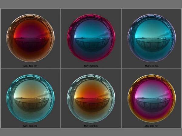
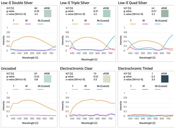
This research is based on extracting glass material properties from LBNL Optics glazing database of more than 4700 entries, containing spectral data of Transmittance (T) and Reflectance on coated and uncoated sides, measured at the normal incidence usually at 5nm intervals. Since this software is used for optical and thermal characterization of glazing, it represents an ideal resource for color matching of glass selection for energy requirements with those in design visuals. In order to account for different visual effects, 6 glass samples were chosen. Four samples are based on green colored soda-lime glass with different silver-based coatings, as well as electrochromic glass in clear and tinted state. Glass samples’ spectral data and respective optical and thermal properties are shown in Figure 2.
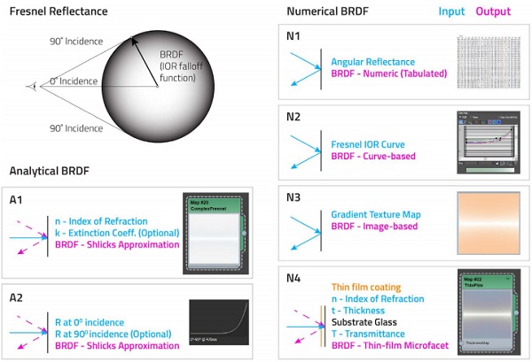
While it is possible to obtain angular spectral reflectance data (from 0˚ to 90˚ incidence angle, usually in 10˚ increments) on-demand for ultimate accuracy when simulating gonioapparent coatings, in most cases LBNL Optics data represents sufficient resource for reflectance characterization. Two main approaches are used to define BRDF: Analytical and Numerical - Figure 3.
Analytical models use either Reflectance data at 0 and 90 incidence angles (A2), or n and k (A1) as an input, while BRDF is computed using Schlick’s method [14]. Numerical approaches include Tabulated angular reflectance data (N1), Custom Fresnel IOR curve (N2), Gradient texture map (N3), and already mentioned thin-film model (N4). While numerical methods may offer higher flexibility and custom Fresnel reflectance, they are computationally more expensive than analytical methods. This paper used A2 model for creating BRDF.
4.2 Geometry Definition
Glass pane can be geometrically represented through three models: Single surface, HalfSurface, and Volume. Glass pane modeled as a single surface, often referred as a thin glass model, is the most computationally efficient model with reasonable accuracy and therefore the most common approach in the building industry for both architectural engineering and visualization.
However, this model does not account for many light effects such as multiple refraction and reflection, total inside reflection, caustics by glass volume, dispersion, etc. This approximation also produces a discrepancy between qualitative and quantitative simulation procedures. In quantitative simulations, such as Radiance, transmissivity replaces transmittance to account for multiple light reflections, as defined by Navier-Stokes equations and described in [15].
However, this increase produces a slightly brighter color in visualizations. Therefore, for qualitative simulations, transmittance should be used instead. When exporting Radiance glass material definition from LBNL Optics, the program automatically applies transmissivity coefficient and exports transmissivity RGB values.
However, for accurate color representation in qualitative simulations, RGB values should be extracted from spectral data through CIE chromaticity coordinates XYZ and translated to the sRGB color space as this is the most common standard in the visualization industry. Alternatively, RGB values from the rad file may be used instead, knowing the values slightly differ from reality, depending on the glass thickness.
The default glass material in Radiance is a simplified dielectric model defined only through RGB transmissivity values derived from Transmittance. Radiance Dielectric material may receive additional two parameters: index of refraction (n) and Hartmann constant (Hc), that describes how the index of refraction changes as a function of wavelength, to override default values for a glass of 1,5 and 0 for n and Hc respectively that are immutable parameters in Radiance glass material.
Both materials assume the same Reflectance properties on both glass sides. This has its limitations in regard to the accurate reproduction of optical properties of modern selective coated glass products such as Low-E coatings, electrochromic and liquid crystal glass among others, that have different reflectance properties on coated and uncoated sides. Therefore, to account for specific reflectance parameters on each side, double-sided surface BRDF model has to be used.
RGB rendering engines generally do not support this model type, with the exception of Radiance, while the most advanced spectral renderers like Ocean are capable to handle double-sided transparent materials. While the model performs quite well for distant flat glass surfaces, as shown in Figure 6 and Figure 7, it cannot accurately describe optical effects of curved glass at a higher incident angle nor multiple reflections that occur from two glass pane sides, visible in close-up views, causing saturation and optical distortion, design aspects relevant for increasingly popular undulated glazing.
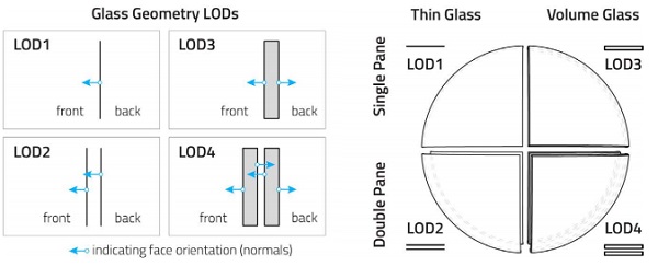
This model may be used to represent IGUs by single or multiple surface model, defining LOD1 and LOD2 respectively - Figure 4 (left). However, if IGU is modeled as a single glass surface material, the model will under-predict transmittance drop at higher incident angles. Therefore, for an accurate representation of IGU with a single surface model, angular BRDF has to be computed, as demonstrated in [2].
Half-Surface: This model is based on the single surface model, but it can account for volumetric effects. Both glass pane sides are modeled as single surfaces with their surface normals facing outwards. To account for correct optical behavior, each surface share of reflectance and transmittance should be calculated and assigned to each surface. Since not many rendering applications do not support two-sided materials, this model was not considered in this study.
Volume glass: The model denotes the best geometry model for representing all possible optical effects, as it exactly represents the real world objects. When representing IGUs, volume glass model may have single geometry - LOD3, and multiple geometries - LOD4 - Figure 4 (left). Yet, this model is computationally more expensive than the surface model. When defining transmittance properties in volume glass model it is important to model glass geometry thickness to match the measured sample.
In contrary, defining color without defining light path length will produce unreliable colors due to the attenuation effects as a function of light path length. Additionally, laminated glass may be characterized as a single volume or modeled as multiple volumes representing each layer including lamination foils. In most renderers, due to the lack of interface material definition, these volumes have to slightly overlap to respect energy conservation laws and properly calculate exit rays.
4.3 Experimental Scene
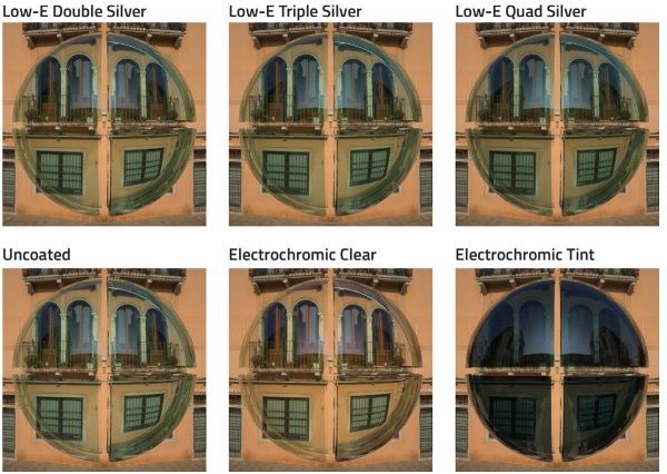
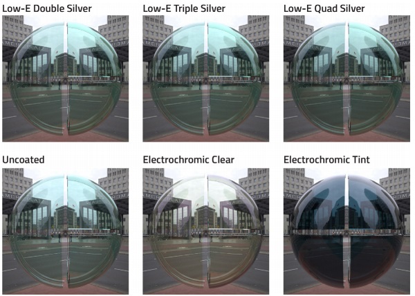
The experimental scene was created to compare two main glass geometry models: Thin vs. Volume both represented as a single and double pane composition, thus portraying all four glass geometry LOD models of IGUs in a single image. Each of the LOD is modeled as a quarter of the sphere and combined they compose full shader ball geometry - Figure 4 (right). The model is capable to visualize full range of incidence angles and demonstrate differences in LODs regarding optical effects such as color saturation caused by attenuation effects and total inner reflection, multiple reflections of IGUs, optical distortion of volume glass, etc.
The scene was illuminated by the HDR Images spherical environment, representing sunny and overcast sky conditions, with the dynamic range of 24EV and 6 EV respectively. HDR images were chosen to be highly detailed and textured to allow better comparison of all analyzed optical effects and color matching. Additionally, HDR images have vertical symmetry in order to provide the same background texture and reflections for comparing surface and volume glass models. Illumination spectra of HDR images was neutral and closely fit the CIE D65 standard spectra.
Visualization was performed using full spectral simulation and bi-directional Metropolis light transport in Ocean [16], to allow the highest possible color accuracy and account for caustics. Furthermore, the experimental setup is planned to be used in future work as a benchmark for other glass experiments illuminated by various types of illuminants with arbitrary spectral distribution and white point.
4.4 Color Management
Given a source illuminant, glass material with arbitrary spectral distribution from LBNL Optics and the standard observer color matching functions, CIE standard method is used to derive a tristimulus XYZ values and subsequently sRGB values for transmittance glass color, applicable only for RGB rendering workflow [17], while spectral renderers perform color conversion automatically after the simulation - Figure 5.
Another important aspect in color management and accurate color conversion from XYZ to sRGB space is the Correlated Color Temperature (CCT) of the illuminant or so-called white balance expressed in [K]. While this step is performed after the spectral simulation, RGB workflow requires color conversion to sRGB before the simulation - Figure 5. The last step in simulation workflow is the tone mapping that converts High Dynamic Range (HDR) image to Low Dynamic Range (LDR) image, suitable for displays.
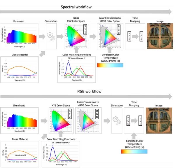
Tone mapping may be neutral eg. correcting only luminance of the pixels without affecting the color or may have filmic effects reproducing altered colors as captured via CCD cameras and old 35mm films. Figure 5 provides an overview of the two most common rendering approaches concerning the handling of spectral data: Spectral and RGB workflows. While spectral renderers have superior color management and are able to simulate more optical effects, they are computationally more expensive.
On the other hand, RGB renderers are much more common across the CGI industry and much more practical for real-time applications, they have limitations in color management and cause inaccuracies in a visual color representation of materials when illuminant and/or material spectra have sharp peaks and valleys. One approach that combines the best of both approaches uses spectral prefiltering and sharp color primaries to account for spectral effects at reasonable commutation cost [18]. Unfortunately, this approach is not available in commercial rendering tools and therefore is neglected from the overview.
5. Results
Results are comprised of two sets of images representing one set of 6 chosen glass samples under two different HDR environments. Glass samples under sunny with the clear sky are shown in Figure 6, while samples under the overcast sky are shown in Figure 7. Color comparison of the same glass sample under different illuminant, in this case, is not possible due to the high transmittance values of the glass that emphasize background images’ colors. Therefore, the paper focuses on the comparison of LODs in the same image and under the same illuminant.
With every light interface, the light ray is split on the transmitted and reflected component. Therefore, for every glass surface interface, there will be as many reflections as light bounces, manifested as slightly shifted images of the reflected environment. These reflections are not the same intensity, and, in most cases, number of surfaces will determine number of distinguishable reflected images. Shifting distance is a function of incidence angle and thickness between the glass panes.
Effect of multiple reflectance of the environment is more visible in Figure 7 in the LOD3 in the upper right region of the shader ball. In the curved glass, the reflected environment will not only be translated, but also distorted. Since experimental setup contains the same curved glass ball model, results show equal levels of optical distortion of the background image for each LOD across all samples. LOD1 and LOD2 shows no optical distortion since the surface glass model is not able to represent accurately this phenomenon, even when using multiple surfaces.
To account for this effect, volume glass model has to be used either as a single – LOD3, or multiple volumes – LOD4. It is clearly seen that for each additional volume, level of optical distortion is higher and increases at the higher incidence angles. This effect is particularly important for curved glass, and therefore it is recommended to use LOD3 and LOD4 when representing curved glass geometries.
Color differences between LODs are very low at normal incidence (close to the center of the image). LOD1 and LOD2 exhibit no color difference with the increase of the incidence angle since there is no light attenuation that produces color saturation. This phenomenon is displayed for LOD3 and LOD where volume glass model saturates the colors, especially at the borders of the ball where total inner reflections occur.
6. Discussion and Future Works
This paper demonstrated possible workflows and LODs for physically-based virtual prototyping of the glass. Therefore, it represents the foundation for future work that will explore glass visualization under illuminants with complex spectra (e.g. artificial lighting) and mixing spectra scenarios (e.g. sunset and twilight when artificial lighting is switched on), especially focusing on spectral and RGB workflows and comparing their outputs.
Moreover, the future research will be focused on immersive virtual prototyping of adaptive facades and explore the relationship between dynamic behavior of smart switchable glazing and a real-time interactive occupant control by simultaneously analyzing both qualitative and quantitative aspects. Additionally, research is planned to expand to other materials and façade systems such as plastics, ETFE, media façade systems with LED, complex fenestration systems and building-integrated photovoltaics.
7. Acknowledgements
We would like to thank to the company Eclat Digital for providing their support, software and performing simulations.
References:
[1] G. W. Larson and R. Shakespeare, Rendering with Radiance : the art and science of lighting visualization. Space & Light, 2003.
[2] J. De Valpine, “Building Better Glass Materials in Radiance,” in 2009 International Radiance Workshop, 2009.
[3] David Barker, “Chasing Transparency - MERCK LIQUID CRYSTAL WINDOWS,” 2018.
[4] C. Reinhart, M. Landry, and P.-F. Breton, “Daylight Simulation in 3ds Max Design 2009 – Getting Started,” Daylight Simul. Autodesk 3ds Max Des. 2009 3ds, pp. 1–23, 2009.
[5] C. F. Reinhart, M. Landry, and P.-F. Breton, “Daylight Simulation in 3ds Max Design 2009 – Advanced Concepts,” Daylight Simul. Autodesk 3ds Max Des. 2009 3ds, pp. 1–23, 2009.
[6] “Glass Pro - Glazing simulation for building facades | Saint-Gobain Glass Scandinavia.” [Online]. Available: http://scandinavia.saint-gobain-glass.com/content/glass-pro-glazing-simulation-buildingfacades. [Accessed: 03-Apr-2019].
[7] “AGC.” [Online]. Available: https://www.yourglass.com/archiglassvisualiser/#!Home!init. [Accessed: 03-Apr-2019].
[8] “Guardian Glass AnalyticsTM.” [Online]. Available: https://glassanalytics.guardian.com/MVC/Visualizer/Standard. [Accessed: 03-Apr-2019].
[9] B. Burley and W. Disney, “Physically-Based Shading at Disney.”
[10] D. Zhang, H. Yabe, E. Akita, P. Wang, R. I. Murakami, and X. Song, “Effect of silver evolution on conductivity and transmittance of ZnO/Ag thin films,” J. Appl. Phys., vol. 109, no. 10, 2011.
[11] M. Junghähnel, “Advanced Glass Refinement by Thin Films - Trends and Challenges of Thin Film Technologies for Windows and Facade Glasses,” in 4th G.A.S.T. Travelling Conference ”Energy efficient Buildings”, 2013.
[12] G. Ding and C. Clavero, “Silver-Based LowEmissivity Coating Technology for Energy-Saving Window Applications,” in Modern Technologies for Creating the Thin-film Systems and Coatings, N. Nikitenkov, Ed. IntechOpen, 2017, pp. 409–431.
[13] L. Belcour and P. Barla, “A practical extension to microfacet theory for the modeling of varying iridescence,” ACM Trans. Graph., vol. 36, no. 4, pp. 1–14, 2017.
[14] C. Schlick, “An Inexpensive BRDF Model for Physically-based Rendering,” in Proceedings of Eurographics ’94, Computer Graphics Forum v13, n3, 1994, pp. 233–246.
[15] G. Ward, “Behavior of Materials in RADIANCE.”
[16] “Home - Éclat Digital OCEAN.” [Online]. Available: https://www.eclat-digital.com/. [Accessed: 20-Apr-2019].
[17] B. J. Lindbloom, “Useful color equations,” Useful Color Equ.,< http//www. brucelindbloom. com/index.html, 2010.
[18] G. Ward and E. Eydelberg-Vileshin, “Picture Perfect RGB Rendering Using Spectral Prefiltering and Sharp Color Primaries,” in Rendering Techniques 2002 - Thirteenth Eurographics Workshop on Rendering, 2002, pp. 117–124.


