

This paper was first presented at GPD 2019 by Massimo Maffeis, Marco Bombonato, Alberto Consolaro and Luca Barbieri from Maffeis Engineering S.p.A., Italy.
The architectural complex shape led to the need for integrated design among all the different personalities involved: clients, architects and engineers. The “One Single Model” (OSM) approach rises, in our experience, as the best tool to manage complex buildings through the different engineering branches. This approach aims at creating a single parametric 3D model containing every building information and capable of being associated with all the different design phases. The goal of the present study is to show how the OSM approach can be applied to the structural calculations of the curtain walls; a case study will be presented in which our tool permits to have an automatic analysis process with, as the input, a complex geometry coming directly from the main model and, as the output, a structural analysis of all the glazed panels.
Introduction
In recent years the architectural concept of the façades has changed radically: the curtain wall has left its pure role of division between the internal and external environment. Playing with transparencies, refractions and complex geometry shapes the building skin has become, on one side, a window on the world and, on the other side, a viewport on the building. The engineering of this new architectural concept, leaving the structural, acoustic and thermo-hygrometric performances unchanged, is the required challenge for every architectural project.
The management of this process involves different personalities including the clients, the architects, the designers, the construction companies and many others. The large number of interested parties makes it necessary to develop a workflow that, starting from the main concept, develops towards each branch of the project, updates the initial information step by step and makes them accessible to the other branches in real time.
The main concept can be identified as a single 3D parametric model of the building containing all the structural, architectural or economic information that will be useful in the design phase or under construction. One single model nowadays is not able to directly handle every design computation and, for this reason, the model has to be interfaced with all the required specialized software down to the desired level of detail.
In structural façade field, the OSM contains all the information for the static and dynamic analyses:
- Global position;
- Geometry;
- Boundary conditions;
- Glass Build up;
- Specific load condition (barrier load position, wind tunnel test results, etc.).
Once the data are collected, a tool generates a global finite element model which allows to identify the most critical glass-pane conditions. Then other tools manage this highlighted pane with specific and more precise analyses. At the end of the process, if the panes satisfy the checks, then the original model is automatically confirmed, otherwise it is updated with the new information.
For the purpose of this work the OSM is represented by a 3D RhinocerosTM geometry parameterized using the Grasshopper plug-in. Through an automated procedure, the geometry is automatically imported as a Strand7 model based on the different input parameters. The procedure was made in #C language, that allows the system automation and interface between the different components.
Theoretical references and methods
All the finite element analyses are performed using a “level 1” plate modelling using the Enhanced Effective Thickness method [1] to define the equivalent thickness of the four nodes isoparametric elements (Quad4). The partition of external uniformly distributed loads (load sharing) for the insulating glass units follows the [1], [2] indications both for the global and for the single panel finite element model. For the single panel a specific tool allows to determine the effective partition of the barrier load case for the insulating glass unit. Both the loads value and the partial coefficients are customizable to satisfy the growing international demand.
In order to demonstrate the goodness of the procedure a case study, based on the design of a real structure, has been conducted and a comparison between a reference model implemented in SJMepla and the St7 single pane model is tested and the results have been reported at the end of this work.
The One Single Model and the Global Finite Element Model
The OSM is the new frontier in the building sector, since it allows to efficiently manage and interface the integrated design of all the parties involved. The main features of the model have to be the ability to store any type of information and the ability to make them easily available and updatable in a short time. To be able to reach the structural results (stress, deflection, nodal reaction) for all the glass panels, the architectural model needs to be converted into a numerical model, which is built as an assembly of finite elements.
According to [3], the geometrical interface has no parametric intelligence that may be used to directly generate the calculation model and this conversion has been achieved through a Grasshopper script. This tool, which has been developed by Maffeis Engineering research and development team, allows to assign a set of parameters to each geometrical element and through the Application Programming Interface (API), it automatically exports geometries and properties to a “global” Strand7 finite element model.
The creation of this model has two main purposes: on the one hand, it provides a preliminary analysis useful to determine the pane subjected to the most critical condition; on the other hand, it allows the engineer to preliminary check the results, saving up the time necessary for the most accurate analyses. Furthermore, the nodal reactions of the global analysis can be used as stresses to analyse the overall behaviour of the mullions and the transoms.
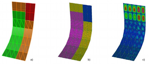
Figure 1 shows the typical workflow for the structural branch of the integrated design. The first step is the construction of the OSM, which contains all the available information of the building (structural, physical, economical etc.); the second step is the extraction of a sub-model containing only the information necessary for the façade structural analyses (1a); the third step is the construction of the global finite element model (1b); the last step is the preliminary structural analyses of the whole façade (1c).
The Single Panel Finite Element Model
The last step of the OSM façade structural workflow is the detailed analysis for the worst case scenario. The modern codes of design require a set of standard tests and checks for the glass unit and the Maffeis Engineering research and development team has developed a procedure to take them into account. This procedure includes tools that automatically receive all the information, from the main model and the global analysis results as an input and return the check results as the new information to the OSM.
The state of the art of the procedure includes four subroutines which accomplished different tasks:
• The effective load sharing of the single glass unit subjected to a concentrate loads: the tool provides a combination of the loads and the pressures which approximates the effective behaviour of the single glass unit. The new load combination will be automatically exported as a load case for the single panel combinations. This tool supports- both concentrate loads and linear loads (barrier load); both double and triple glazing glass unit; both rigid and elastic constraints.
• The “conventional” glass analysis: the tool provides the conventional glass analysis for the single glass unit.
• The “staged analysis”: the tool provides an analysis that is able to take into account the non-linear behaviour of the glass unit subjected to load with different application period. The time periods are defined “stages” and the tool allows to consider the time scale differences, in terms of stiffness and strength of the glass pane, and the non-linear geometrical behaviour from one step to another. The state of the art of this tool allows two main stages: the “long term loads stage” which brings together the dead load, the climate load and the snow load; the “short term load stage” which brings together the live loads and the wind load. Both the “Staged Analysis” and the “Classical Analysis” automatically attaches to the OSM a report which includes the main engineering information of the analysis. The tools support both the double and the triple glazing glass unit; both the rigid and the sealing constraint conditions; both the V.E.A., the two side and the four side supported glass unit.
• The soft-body impact on glazed surfaces: the tool has been developed in partnership with the University of Parma [4], and allows the evaluation of the response of glazed surfaces with respect to impulsive dynamic action.
The application of the One Single Model Procedure, a case study
The case study has been inspired by a real Maffeis Engineering project. The extension of the curtain wall is about 280 m2 and it is composed by 60 indipendent panels: the shape of the wall starts with a “skylight” whose panels are almost horizontal and it ends with a vertical façade (fig.2a). The panels of the vertical façade are rectangular and their dimensions are respectively 2m and 4m; the panels of the “skylight” are triangular and their principal dimensions are respectively 2m and 4m.
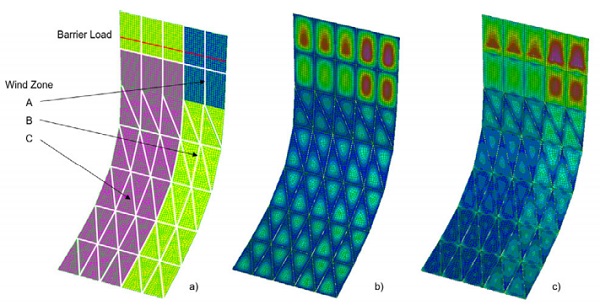
All the edges of the panels are supported normally to the surface. At the top of the curtain wall there is a floor space and the barrier load has to be applied to the highest panels. It is supposed that the importance of the building requires a wind tunnel test and three different wind pressure zones have been extracted from the test (Tab.1, Fig.2a).
The same glass build up has been used for all the panels: glass units are made of a symmetric “double glazing”; each pane of the double unit built of a single monolithic glass. In order to make the analyses faster and more legible, the global finite element model has been split into two simpler models: the first one is used for the SLS combinations and the second one for the ULS combinations. Each model has 120 panels (60 for the outer pane and 60 for the inner pane).
The mesh is composed by four nodes isoparametric shell elements and the average size of the single element is 20 cm. The distributed loads are applied normally to the surface of the elements. For the barrier load case, null beam elements are created through the highlight plate nodes and the linear load P=1 kN/m is applied normally to the plate surface following the beams local reference system.
The panels have different space orientations: to apply the in- and outof-plane constraint condition, it has been necessary to extrude the beam elements from the edge nodes of the panels, perpendicularly to the panels itself.
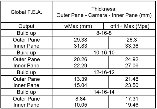
Three different types of beam are created using cinematic “end release”: the first one simulates a normal constraint and it transmits only normal forces to the panels; the second one simulates the simple support and transmits normal and shear forces in one direction to the panels; and the third one simulates the double support and transmits normal and shear forces in two directions to the panels. The global model preliminary analyses (Tab. 2) have been taken into account four different glasses build up, changing the plates effective thicknesses.

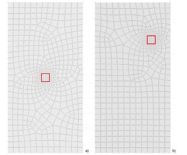
The results (fig.2b, fig.2b) show that the most critical panel is the top right corner rectangular glass unit, both in the displacement combinations and in the stress combinations. The Combination that generate the worst case is the wind suction as the primary load case and the barrier load as a combination load case. To test different glasses, the global analysis has been replied four times. Table 2 provides the numerical results for the worst case scenario extracted by the global analyses.
With reference to the maximum allowable displacement wlim = min (B, H) / 100 = 2000 / 100 [mm] = 20mm, the OSM procedure has been further developed only for the 10-16-10 and the 12-16-12 glasses build up. The geometry of the most stressed panel has been exported in a new finite element model. The panel has been re-meshed and the maximum size of the elements has been set to 10 cm; the constraint condition has been updated following the new reference system of the model.
The “climate load” condition, the effective “barrier load sharing pressure” and the impact load have been considered in these analyses. The first step of the single panel analysis is the definition of the “effective barrier load sharing pressure”. Under the condition of isochoric behaviour of the glass camera, a positive pressure is produced under panes deflection; this pressure can be evaluated through numerical iterative analysis.
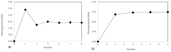
Figure 3a and Figure 3b show the iterative progresses of the sharing pressure both for the 10-16-10 and for the 12-16-12 glass unit. The analyses show that for the 10-16-10 camera the sharing pressure Pb_10 = 0.143 kPa and for the 12-16-12 camera the sharing pressure Pb_12 = 0.149 kPa. To ensure the goodness of the method a results comparison have been produced between the “Maffeis Engineering Iterative Tool” and the commercial software “SJ MEPLA”; these comparisons have been reported in Table 3.
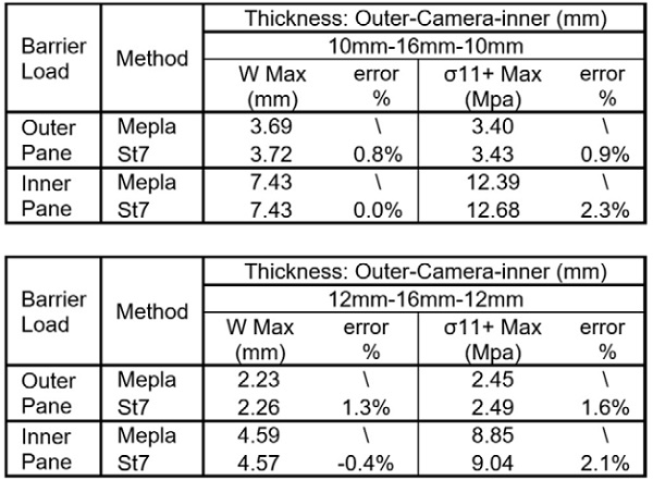
The results provided by the Maffeis Engineering tool are in a very good agreement with the commercial software and the relative error is always under the 2.5% both for the deflection and for the stresses. At the end of the process the “sharing pressure” has been automatically added to the barrier load case in the single panel finite element model.
The next step is the SLS and the ULS analyses for the single panel. The finite element model has the same numerical features of the model used for the barrier load calculation and rigid out of plane constraints have been used. For the present work two different calculations have been produced. In the first calculation all the loads have been applied considering the same load application period: this standard calculation has been called “un-staged analysis”.
In the second calculation the “long term” loads have been applied to the undeformed pane and the nonlinear analysis has been run (stage 1). Once the analysis has been completed, another calculation has been run (stage 2) applying the “short term” loads to the deformed shape obtained in the stage 1 analysis.
This procedure has been called “staged analysis”. In order to demonstrate the goodness of the method, a comparison- between these two methods and an un-staged analysis performed by the using of the commercial software SJ MEPLA, has been produced and the results have been reported in Table 4. The results show a very good agreement between the two un-staged analyses.
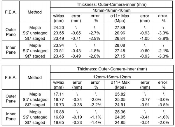
The sums of the errors caused by the different finite elements used (SJ MEPLA used 9 nodes isoparametric elements) added to the errors caused by the different load sharing of the single glass unit subjected to distributed loads, are always less than 0.65 mm in terms of maximum out of plane deflection, and less than 0.95 MPa in terms of maximum principal stress.
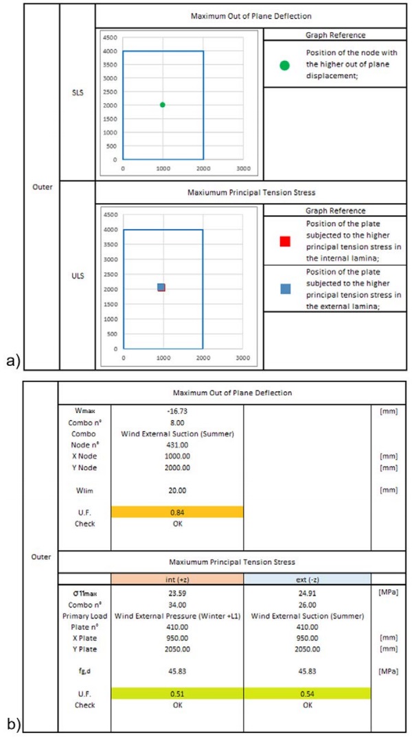
The staged analysis maximum errors increase respectively to 0.71 mm and 1.05 MPa due to the non-linearity of the analysis. At the end of the analyses a table report is produced. This report will be attached at the OSM as a new information, which could be consulted by each person involved in the project. An example of the table report is shown in Figure 4.
The OSM procedure allows one further step. Following a confirmed approach, an innovative tool, presented in [4], has been added to the automatic OSM procedure to evaluate the response of glazed surfaces with respect to impulsive dynamic action applied in a plate random position. The single panel geometry has been exported in a further finite element model and the mesh has been updated in order to follow the [4] instructions.
The procedure allows any position of the plate to be considered as an impact point and Figure 5 shows two possible configurations. For the impact test analyses only 12-16-12 glass build up has been considered. The 10-16- 10 panel, indeed, does not satisfy previous deflection checks and this glass build up has been rejected. The impact test results and their comparison with the SJ MEPLA software results have been reported in Table 5.
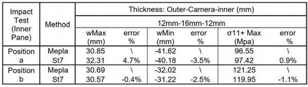
The results show a good agreement between the Impact tool and the commercial software with a maximum error below five percent. At the end of the analyses, the impact test results will be attached to the main table report that has been shown in figure 4.
Conclusions and future developments
The One Single model procedure has been developed to simplify the interaction between the different personalities involved in the buildings design. All the subroutines, the steps and the automations follow the “Integrated Design philosophy” and the result is a procedure able to collect all the building information in a single dynamic and upgradable model. A structural example has been produced to demonstrate the goodness and the utility of the procedure and the results are in perfect agreement with the engineering expectations.
The Maffeis Engineering Research and Development team is working to constantly upgrade the procedure to be always at the forefront in the complex building design. A new full 3d single brick model is under study to model the effective behaviour of the plane and curved laminate glasses and saving up time and material resources. A new and simpler graphical interface, that makes the whole procedure accessible to any type of users, is on the company agenda. The addition of a new “Bomb Blasting” Load case in the OSM procedure is under study in collaboration with the University of Parma [5] and it represent a short term goal to satisfy the new world façade design standards.
References
[1] CNR-DT 210/2013, Istruzioni per la Progettazione, l’Esecuzione ed il Controllo di Costruzioni con Elementi Strutturali di vetro, Consiglio Nazionale delle Ricerche, 2013.
[2] DIN 18008:2010, Glass in building – Design and construction rules, Normenausschuss Bauwesen (NABau) im DIN, 2010.
[3] R. Rempling, D. Fall, K. Lundgren, “Aspects of Integrated Design of Structures: parametric Models, Creative Space and Linked Knowledge”, Civil Engineering and Architecture 3(5): 143-152, 2015.
[4] A. Consolaro, G. D’Ambrosio, M.Maffeis, G. Royer-Carfagni, “An engineered tool for the soft-body impact on glazed surfaces”, Glass Performance Days (GPD), Tampere Finland, 2019.
[5] M. Maffeis, G. Royer-Carfagni, L. Viviani, “An engineering approach for the basic design of glazed surfaces under blast waves”, Glass Performance Days (GPD), Tampere Finland, 2019.


