Source:
Challenging Glass 7
Conference on Architectural and Structural Applications of Glass
Belis, Bos & Louter (Eds.), Ghent University, September 2020.
Copyright © with the authors. All rights reserved.
ISBN 978-94-6366-296-3, https://doi.org/10.7480/cgc.7.4610
Authors:
Thomas Wüest
Andreas Luible
Lucerne University of Applied Sciences and Arts, Switzerland

In the past glass design in Switzerland was based on foreign standards and regulations. Questions raised whether the application of these standards is suitable, as they do not comply with the Swiss Standard SIA 260 –Basis of design. The most used standards are the German technical regulations for the use of glazing with linear supports (TRLV) and the DIN 18008. The Swiss society of engineers and architects (SIA) initiated a structural glass standard committee with the task to develop a Swiss glass design standard.
The new Swiss glass design standard is based on the same concept as the Eurocode10 "Design of Structural Glass", which is currently in preparation. In future, this standard will be the basis of the Swiss national annex of the Eurocode. An important issue in glass design practice is the shear coupling effect in laminated glass. The standard allows taking into the shear coupling effects and thus will lead to more economic pane thickness.A new concept was developed to meet post failure requirements without time-consuming and costly tests. Anew approach for the determination of temperatures in IGU was established to determine the climate loads of insulated glazing units (IGU).
1. Introduction
1.1. The Swiss Society of Engineers and Architects
The Swiss Society of Engineers and Architects (SIA) is Switzerland’s leading professional association for construction, technology and environment specialists. The SIA develops, updates and publishes numerous standards, regulations, guidelines, recommendations and documentation for the Swiss construction industry. Some 200 committees are responsible for a continuous update of existing and the development of new standards (SIA, 2020).
In 2003 a new generation of swiss codes (260 series), which are based on the same safety concept as the Eurocodes, were published. As a full CEN member and as part of an agreement between the countries of the European Union (EU) and the European Free Trade Association (EFTA), Switzerland has committed itself to reducing technical trade barriers by adopting European EN standards. This means in future, European standards will be adopted as national standards. Swiss standards that contradict an EN must be withdrawn after a transition period. Therefore, the Eurocodes with its Swiss National Annexes are also applicable as SN EN 1990 to SN EN 1999 in Switzerland.
The objective of the SIA is to create guidelines for project planning that do not unnecessarily restrict the creativity of planners. Therefore, the Swiss standards are based on the principle, that they are not kept too brief nor too extensive. The SIA standards should address the professionals in practise as a central instrument of aid rather than an instruction manual. Further, it is not foreseen that the standards restrict unduly the field of the structural engineers own responsibility. The standards should not inhibit development or innovation (Cogliatti, 1978) (Lang & Fischer, 10/2014).
1.2. European Glass Design Standard
Structural Glass applications became very popular in the building sector. This is also the reason why the next generation of Eurocodes will also contain a Eurocode 10 "Design of Structural Glass". The CEN/TC 250/SC 11 “Structural Glass” started in 2016 to work on a CEN TS on Structural Glass. It is expected that the Eurocode 10 will be available at the end of 2023 or beginning of 2024 (Feldmann & Di Biase, 2018).
1.3. Brief History of Glass Design in Switzerland and linked Problems
The SIA never had a standard or guideline for glass design. Only within the SIA 329:2018 Windows and French Doors and SIA 331:2012 Curtain Walls, only allowable bending stresses for glass are listed in an annex. However, both standards are in line with the SIA 260 series standards and based on the semi probabilistic design concept. Further instructions how to deal with the allowable stresses are missing.
Since 1980, the SIGAB (Swiss institute for glass in buildings) publishes recommendations and guidelines concerning safety issues of glass. The guidelines propose a minimal glass thickness for some simple cases, which are based on best practice or foreign standards. Because SIGAB is located in the German part of Switzerland, the application of the German TRLV (technical regulations for linear supported glazing) (TRLV, 2006) since 1998 was obvious.
In practice, the application of foreign standards was not satisfying because some of the regulations have been seen as “too strong” and so come that certain points have been neglected. In some cases, only the allowable stress of TRLV (same as later in SIA 329 & SIA 331) and favorable rules were applied and unfavorable rules were neglected. In 2010, the DIN 18008 (DIN 18008-1, 2010) replaced the TRLV in Germany. The transition from TRLV to DIN 18008 changed the safety concept from allowable stress to the design values with safety factors.
The result was that some engineers applied the TRLV, while others applied the DIN 18008. In principle, the SIA allows the application of foreign standards, which are state of the art, especially if a national standard is not available. In consequence, engineers that relied on TRLV should also move to DIN 18008. This process was long and difficult. Finally, the DIN 18008 became the most used glass standard in Switzerland within the past years.
Beside all the improvements and compatibility with SIA 260 series, the DIN 18008 for some planers contained “too strong” constructional restrictions. As the Standards is not an officially approved design standard, this resulted in a free interpretation of the DIN 18008 in design practice, which led to different solutions for the same problem. For example, fully glazed bottom clamped float glass balustrades were designed according DIN 18008-2:2010 with a construction factor kc= 1.8 instead of 1.0, which is only allowed for at least two sides supported glass. In addition, detailing requirements according DIN 18008 such as a minimal clamping depth, handrail or edge protection, have been ignored.
1.4. SIA 268 Committee
The SIA, SIGAB and the Competence Centre Building Envelope at Lucerne University of Applied Science initiated the development of a national glass standard for Switzerland in order to overcome the unsatisfactory situation for planners and engineers. The SIA Committee 268 started in 2014 with the task to develop this new glass design standard for Switzerland. The group, established by the SIA, consists of representatives of the glass industry, planers, façade manufacturers, façade engineers and research institutions. Some of them also represent one of the professionals association of the metal and facade construction industry.
The SIA 268 committee is part of the SIA 260-Series structural design standards. As the new glass design standard is new standard and not based on a previous standard, it is released as the so called “SIA Guideline2057”. After a probation period of 5 years, the data sheet will be transformed into the standard SIA 268. In addition, the SIA committee is the mirror group for all glass relevant EU guidelines and standards and, therefore, actively cooperates and participate on an EU level.
One objective during the development of the guideline SIA 2057 was, that it is in line with the current drafts for Eurocode 10. Therefore, the safety concept based on Ultimate Limit State (ULS), Serviceability Limit State (SLS), Fracture Limit State (FLS) and Post Fracture Limit State (PFLS) has been adopted.
2. The SIA guideline 2057
This section gives an overview of the SIA 2057 content and highlights some special regulations and approaches.
2.1. General overview
The structure of the standard corresponds to the typical structure of the existing SIA structural design standard series. During the development of the standards, great importance was given to user-friendliness. Therefore, most of the structural design standards consist only of one single document with all the information necessary. Furthermore, the Standard is not intended to cover all possible application situations, but only those that are most relevant from a practical point of view. The SIA guideline 2057 and future SIA 268 follows this principle.
Chapter 4 defines all the essential rules and boundary conditions for the whole document, where as Chapter 5 deals with the specific components and related special requirements. Subsequent, a few topics from chapter 4 are highlighted; design bending strength calculation, Laminated Glass Design with Shear Stiffness (see 2.2) and the “4 limit states concept” (see 2.3).
Chapter 5 deals with the specific glass applications, called “components” and their related requirements. This includes a tighter definition of the component class, constructional requirements, additional specifications for the ultimate and serviceability limit state (ULS & SLS), requirements regarding the fracture limit state (FLS) and post fracture limit state classification (PFLS). The latter one is discussed in detail in chapter 2.3.
Applications or components, which covered by the guideline are: Vertical glazing, Horizontal glazing, Insulated Glazing Units (IGU), Barrier Glazing, Overhead glazing, Walk-onGlazing, Accessible Glazing, Drive-on Glazing, Components subject to column buckling, Components subject to lateral torsional buckling.
As an example, a horizontal IGU is both a horizontal glazing and an IGU. Therefore, it has to fulfill both sets of requirements. The components are structured in that way that requirements are consistent and additive. This means that an IGU has always higher requirements than a horizontal or vertical glazing. Consequently, an accessible IGU contains the requirements of horizontal glazing & IGU & accessible glazing.
2.2. Laminated Glass Design with Shear Effects
The static behavior of laminated glass strongly depends on the interlayer properties (stiffness). In addition, the interlayer properties depend on the load duration and interlayer temperature. This wide range of variations can hardly be covered with a “simple standard” and various concepts to deal with this issue had been developed. Some standards simplify the problem by neglecting positive effects of interlayer shear stiffness or account full shear bond if it has non favorable effects on glass stress calculations (DIN 18008-1, 2010). Some standards allow a low shear stiffness for certain applications (ÖNorm B 3716-1, 2015) and others allow an “effective glass thickness” with shear effects (DIN EN 16612, 2017).
Due to the lack of regulation in Switzerland, almost all types of shear stiffness consideration had been appliedin the past. Therefore, the SIA 268 committee agreed that the application of shear stiffness must be part of the standard. Regarding the basic principles of the SIA “nothing should be prohibited but appropriate boundary conditions must be set”, a rather simple procedure and amore detailed procedure are noted.
The simple shear stiffness follows mainly the recommendations of DIN 18008-1 & B 3716-1, which means that favorable effects are neglected and unfavorable effects must be considered. On the other hand, some concessions for SLS and ULS are made; for short load durations in SLS a fixed shear module of G = 0.4 N/mm2 is allowed and for ULS the total design bending strength is increased by kVSG= 1.1.
In the more detailed procedure, the engineer must fulfill a the following requirements to account shear stiffness in structural analysis;
- a suitable calculation model (analytic or finite elements (FE)) must be chosen
- the shear stiffness, depending on load duration and temperature, must be determined for every load case
- it is necessary to ensure that the right product is used in fabrication
Surely, the calculation effort increases drastically with complexity of the structure and number of load cases. This means not only structural aspects; the engineer also needs building physics skills to determine the correct temperature range of the glass element. To support the application of shear stiffness, the guideline contains values of load duration and temperature in the Annex. Furthermore, guidance to determine temperatures of glazing structures in summer (or winter) conditions are also provided.
The consideration of shear stiffness leads to “optimized” glass thicknesses, which is desirable. On the other hand, the simplified regulation with no shear stiffness enlarged the safety margin of laminated glass components. For safety reasons, the “old” system has been approved. If the same, simplified requirements are sufficient for thinner, optimized laminated glass components is one of the questions to be asked. This is one of the reasons why the SIA 268 committee adopted the idea of the “four limit states” from the (prCEN/TS 19100-1:2020, 2019).
2.3. The “four limit states” concept
The brittle behavior and lack of ductility and randomness of the surface bending strength leads to the effect that glass layers can completely fail when the stress exceeds its limit. In contrast to traditional construction materials robustness and redundancy requirements are mandatory for glass. Therefore, a “four limit states” concept has been established in prCEN/TS 19100-1:2020 to ensure the robustness and redundancy of glass structures:
- Service ability Limit State (SLS) Limit State that concerns service requirements (deflections, vibrations, ...) of the structure.
- Ultimate Limit State (ULS) Limit State that concerns the maximum load carrying capacity of the construction.
- Fracture Limit State (FLS) Limit State that concerns safety and protection of people and/or the structure during accidental fracture.
- Post Fracture Limit State (PFLS) Limit state that concerns the residual load bearing capacity when one or more glass plies have accidental fractured.
2.3.1. Serviceability Limit State (SLS) and Ultimate Limit State (ULS)
The assignment of the SLS is generally defined by the characteristic combination of actions according EN 1990:2002 (Formula 1) and divided in horizontal and vertical glass applications.
![]()
For the ULS, the combination of actions for persistent and transient design situations according EN 1990:2002 is used. Note that the national Annex NA SN EN 1990:2002 as well as SIA 260:2013 defines γQ,i= 1.0 and therefore is left out in Formula 2.
![]()
2.3.2. Fracture Limit State (FLS)
For the FLS, the situation during or immediately after fracture of glass components is considered. Therefore, mainly issues concerning the safety of people in close proximity to the glass components are regarded. As example the risk of injury by falling into the element or falling fragments.
The verification of the FLS is usually made by theoretical assessments. Therefore, requirements regarding the material selection or construction design are stated. This is strongly depending on the application and defined for each component in chapter 5 of the SIA guideline 2057.
As an example, for vertical glazing over areas with free movement of people the use of single ply glazing’s is limited. Single glass plies are only allowed, if they are linear supported on all edges, exceptional thermally toughened safety glass. Thermally toughened safety glass with top edge over 4m above ground, with or without heat soak test, is not allowed as single ply or external IGU component at all. Punctual supported components need to be laminated glass.
2.3.3. Post Fracture Limit State (PFLS)
There is always a possibility of failure of a glass component and this situation has to be taken into account during design of glass structures. The resistance of the component after failure of one, two or all plies is strongly dependent by the type of glass, size and its support.
Defining PFLS requirements is difficult as it depends on many factors: Is it possible that all plies fail, or just one? Does the failed component receive any load or should it just remain in the structure? If it receives load, how many? Is it a short time or long lasting time event? Is experimental testing required or is a static calculation sufficient?...
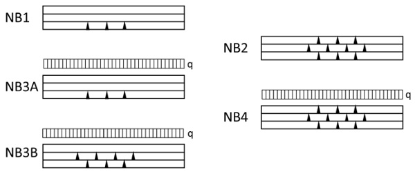
To answer those questions, the SIA 268 committee came up with the “NB-Concept”. Whereas “NB” is the abbreviation for the German “Nachweis im Bruchzustand”, which is approximately “verification in PFLS”. The NB-Concept is based on five different failure modes classes (see also Fig. 1).
- NB0 No additional verification needed.
- NB1 If one (or more) plies fail, the component shall stay in place after failure. No additional load must be applied.
- NB2 If all plies fail, the component shall stay in place after failure. No additional load must be applied.
- NB3 If one (NB3A) or two (NB3B) plies fail, the component must resist the accidental load combination.
- NB4 If all plies fail, the component must resist the accidental load combination.
The required NB class depends on the specific application and is defined in the chapter 5 of the guideline.
For situations with load bearing requirements, the accidental load combination according EN 1990:2002 / SIA 260:2013 (where Ad is the PFLS situation and not a load) is to be applied. Together with the additional definition in SIA 2057 this results in the load combination according EN 1990:2002, given by Formula 3.
![]()
The NB’s especially refer to plies, which means one single monolithic ply of a laminated glass or IGU can fail. This means, that a double glazing unit (DGU) with two laminated glasses consists of 4 plies. If NB1 or NB3A is to be verified, there is still a DGU with three plies remaining!
For NB1, NB3A and NB3B either a calculation with the remaining plies or an experimental testingcan be performed. The assessment of NB2 and NB4 needs experimental testing, because fractured plies cannot be taken into account for structural analysis. The calculation NB assessment (NB1, NB3A, NB3B) underlies the following requirements:
- Fractured plies cannot be taken into account,
- the effect follows the accidental load combination,
- dead load of broken plies must be considered,
- load sharing between the components of IGU’s with remaining closed cavity is allowed,
- climate loads are negligible for NB calculations of IGU’s,
- the fracture of an arbitrary ply should be considered (or defined by an fracture scenario),
- the design bending strength is not modified.
The experimental testing of NB cases should be performed on an appropriate mockup, which includes all relevant details corresponding to the real, as built, situation. Alternatively, in situ experiments are also allowed. The thermal conditions should be chosen according to the real situation and preset at least 4 hours in advance of the experiment. The load application should be in a suitable way to ensure that it remains for the whole duration of the experiment and does not make positive effects.
The main goals of the NB experiments is to prevent people and structures from damage by the failed glass component. Therefore, the component must remain in the mounting condition for at least 24h in partial fractured situations and 12h in completely failed situations. The maximum amount or size of falling fragments is to be defined by the project responsible in advance of the experiment. The experiment is fulfilled when this requirements are met.
However, the NB3A requirement is probably easy to understand, this accidental situation is likely to happen. In combination with the accidental load combination, it is not a too high requirement. The NB3B, where two plies are fractured, might be a more challenging requirement. The idea behind is to gain redundancy. That means that as more plies are used, the more unlikely it is that several plies fail. So come that the NB3B implies that 3 plies is the minimum structure, but it is unlikely that the PFLS is passed and 4 plies should be used.
2.3.3.1. PFLS example
In order to explain the PFLS calculations in prSIA 2057 might be complicated to understand. Therefore, some simple (fictional) examples are provided in this section in order to explain the PFLS calculations in prSIA 2057. Assuming, a barrier glazing of 1m height and 1m length with a characteristic barrier load of 1 kN/m. The effect for ULS and PFLS is shown in Formula 4 and 5.
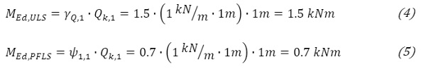
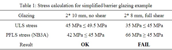
At this point, we already see that the impact of NB3A on a two ply laminated glass (minus one ply results in one ply for PFLS) is often negligible for calculations without shear stiffness. This because half of the structure (1 ply) receives little bit less than half of the load (MEd.PFLS / MEd.ULS = 0.47). The remaining single ply of a 2 ply laminated glazing is no longer seen as “VSG”, therefore the kVSG is reduced from 1.1 to 1.0. As long as the bending stress in the ULS is not close to the design bending stress and ψ1 is 0.7 (or often less, see EN 1990:2002 Table A.1.1), there is only little impact. If the shear stiffness is accounted in ULS, the PFLS with the remaining ply of a 2 ply laminated glass is likely to not pass.
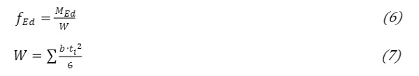
To get some numbers, a few simplified stress calculations are made for the barrier glazing example. To demonstrate the assumption above, the design with shear stiffness is simplified to full shear stiffness (2 times 10 mm is seen as a monolithic 20 mm ply). In addition, the design bending stress calculation is neglected and the characteristic 45 MPa according EN 572-1 is the limit. The stresses are calculated according the following Formula 6 and 7.
As mentioned before, a 2 ply laminated glazing component without shear stiffness is likely to pass NB3A. Whereas a thinner component with shear stiffness likely fail the PFLS, see Table 1.
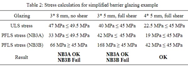
The picture changes a little bit in case of 3 ply laminated glass. Obviously, calculation without shear stiffness will pass the NB3A PFLS, when one of three plies is fractured. Also the calculation with shear stiffness has better chances to pass the NB3A. The higher requirement of NB3B, where two plies are fractured, is still challenging for both calculation methods, see Table 2.
The NB3B is more likely to pass with 4 plies. First, this is a shocking statement because all have the “traditional” thick plies in mind. Therefore, in Table 2 a 4 ply version is added. It is visible that only the 4* 5 mm passes NB3B, with a total thickness of 20 mm glass. This is the same total glass thickness as 2* 10 mm that would pass NB3A with full shear!
To sum up, the NB concept in prSIA 2057 ensures that laminated glass, especially designed with shear stiffness, still provide a suitable residual load capacity. Furthermore, the simplified example shows that a higher NB-requirement does not directly mean more glass mass, it mainly demands more plies. Certainly, this is very much depending on the applied load, load cases, bearing and the component. However, engineers tend to say “Where I used 2*10 mm, I need now 3 plies that makes 3* 10 mm”, that is not right.
2.4. Climate Loads of Insulated Glazing Units (IGU)
Climate loads on modern IGU’s have been investigated in (Wüest & Luible, 2016). Since then, the model has been improved and used as basis for the SIA temperature calculations. In addition, the application of “absorbance classes” for TGU’s and the safety factor γQ for climate actions have been discussed.
2.4.1. Thermal IGU characterization
The SIA 268 committee followed the recommendation that the IGU’s should not be classified according their total absorbance. This because the thermal behavior of a TGU with similar total absorbance vary widely weather they have “usual” coatings, sun protection coatings or thick middle plies. Therefore, the SIA 2057 provides two characteristic IGU setups, a “usual” setup and more absorptive setup with increases and reductions, depending on coating and internal / external shadings.
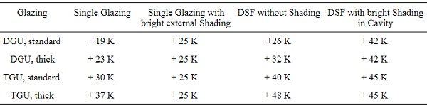
In addition, it is recommended that the temperatures should be calculated if there are special setups or installation conditions. An overview for DGU and TGU temperature differences ΔT as single IGU, IGU with external shading and in (non ventilated) double skin facades (DSF) are shown in Table 3. For comparison only, the DIN 18008-1:2010 says only “+20 K” for all those cases, based on a solar irradiation of 570 W/m2 (instead of 830 W/m2 used in prSIA 2057).
Table 3: IGU Climate Load Temperatures (ΔT) Summer Cases for standard IGU’s (DGU 4/16/4 with LowE Pos. 3 and TGU 4/14/4/14/4 LowE Pos. 2 & 5) and “thick” IGU’s (DGU 8/16/8 with LowE Pos. 3 and TGU 6/14/8/14/6 LowE Pos. 2 & 5)
2.4.2. Load safety factor for climate actions
Another important IGU issue is the safety factor γQ. According to EN 1990:2002 and SIA 260:2013, unfavorable variable actions are multiplied with γQ = 1.5. In combination with a low kmod for climate loads, the load combination “climate” is often predominant for IGU design. The often discussed “lack of IGU failure due to climate loads” led to exception clauses or alternative design strategies, as example within DIN 18008-2:2010 Art. 7.5 or draft DIN 18008-2:2019.
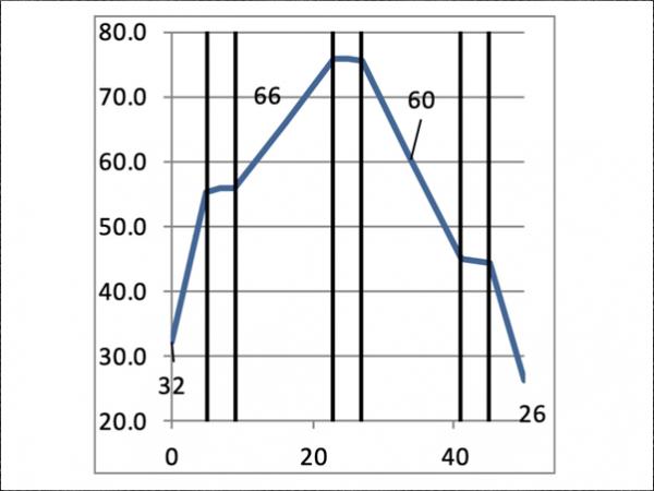
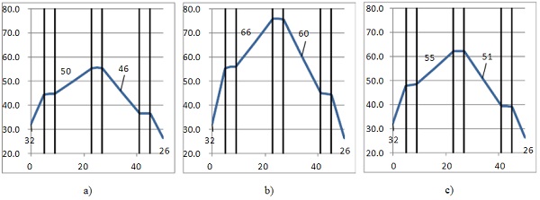
Based on the more sophisticated temperature calculations in prSIA 2057, an increase of ΔT by factor 1.5 is physically not appropriate and should be reduced. To demonstrate that, Fig. 2a shows the standard TGU (4/14/4/14/4, LowE on Pos. 2 & 5) in the summer case according prSIA2057 (830 W/m2, 32 / 26 °C, hsurf = 13.5 / 7.7 W/(m2K)). This results in gas temperatures of 50 °C and 46 °C, in average 48 °C. With a production temperature in winter of about 18 °C, the basic ΔT of +30K according Table 3 shows up. Now, to achieve 1.5*ΔT = 45 K (see Fig. 2b), the solar irradiation must achieve about 1590 W/m2. This is even higher than the solar constant above Earth’s atmosphere of about 1360 W/m2. Even on 1000 W/m2 an external Temperature of 57 °C is needed.
Therefore, the SIA 268 committee recommends a lower γQ for climate actions, γQ,climate = 1.1. The enlarged 1.1*ΔT = 33 K (see Fig. 2c) covers solar irradiations up to 1075 W/m2 or external air temperatures up to 43 °C. The γQ,climate is also applicable for the atmospheric pressure change Δpmet, because a variation 1.5 times higher than the 95% fractal, evaluated by long term measurement data in Switzerland (Neuchatel data from 1913 until now), is hardly possible.
In addition, two exception clauses are also available in the SIA guideline 2057. One for small IGU’s in usual windows, which should not be designed structural every time. Another for IGU’s that only the climate load case is relevant for design; the weakest ply / plies cam be neglected and the remaining component must be design for full ULS load.
3. Discussion
Developing a new standard from scratch is challenging. On one hand, the standard should support glass applications, which are proven in practice. On the other hand, glass needs some special attention when used as load bearing element.
The main goal of the new guideline is, to harmonize glass design within Switzerland and to create a standard, which complies with the future European glass design standard. During the development of the SIA guideline 2057, the committee studied existing standards of foreign countries in depth. Conforming with the philosophy of the SIA construction standards, the SIA 2057 guideline addresses most common glass applications without overregulation.
The guideline offered opportunities to include new approaches for the shear stiffness application and a PFLS verification with the NB-Concept. As demonstrated in the examples, there is low impact for traditional designed or existing glass components. However, it ensures that optimized glass components still possess safety requirements in terms of robustness and redundancy, especially such ones with shear stiffness.
Another focus during the development of the guideline was the determination of climate loads as most calculations still refer to the work of Feldmeier (Feldmeier, 1995) and the application in the TRLV (TRLV, 2006). It is evident that those simple recommendations are not suitable for modern triple IGU and based on a deterministic design approach. The SIA guideline now updates those recommendations and enlarges the field of application. In addition, it is desired that IGU temperatures are calculated by a suitable model, as it is written in (DIN EN 16612, 2017), but with the addition of seasonal boundary conditions.
In this context, the issue of load combination factor (γQ) for climate loads is addressed. Due to the natural limited variation of climate conditions, the redundancy given by the NB-concept and low occurance of climate load failures in practice, the combination factor γQ = 1.1 for climate loads as dominant load is proposed as sufficient. Furthermore, other loads are usually relevant for design.
4. Conclusion & Outlook
Glass with its unique transparent feature is a popular building material and the use of glass will probably rise in future. The new guideline should support the use of glass in an adequate way by the combination of latest research results, experience and standardization. In addition, it supports innovation and development of new solutions in consideration of the special safety and robustness requirements of structural glass.
5. Acknowledgements
The authors acknowledge the Swiss Society of Engineers and Architects and the members of the SIA committee 268; Christoph Haas, Claude Hutmacher, Bruno Kassnel-Henneberg, Reto Meili, Jurij Patocchi, Corsin Roffler, Mario Russi, Daniel Schaad, Daniel Schärer.
6. References
Cogliatti, A.: The role of the Swiss Association of Engineers and Architects (SIA) in the development of prestressed concrete. Schweizerische Bauzeitung, S. 279 (1978). doi:http://doi.org/10.5169/seals-73671
DIN 18008-1 Glas im Bauwesen -Teil 1: Begriffe und allgemeine Grundlagen. Berlin: Deutsches Institut für Normung (2010)
DIN 18008-2 Glas im Bauwesen -Teil 2: Linienförmig gelagerte Verglasungen. Berlin: Deutsches Institut für Normung (2010)
DIN EN 16612: Glas im Bauwesen - Bestimmung des Belastungswiderstandes von Glasscheiben durch Berechnung und Prüfung. Brussels: CEN - European Committee for Standardisation (2017)
EN 1990: Eurocode - Baiss of structural design. Bruxelles: CEN (2002)
Feldmann, M., & Di Biase, P.: The CEN-TS "Structural Glass – Design and Construction Rules" as pre-standard for the Eurocode. ce/papers, S. 71-80 (2018). doi:https://doi.org/10.1002/cepa.911
Feldmann, M., & Kasper, R.: Guidance for European Structural Design of Glass Components. Luxembourg: Publications Office of the European Union (2014). doi:10.2788/5523
Feldmeier, F.: Entwicklung eines vereinfachten Verfahrens zur Berücksichtigung der Klimabelastung bei der Bemessung von Isolierglas bei Überkopfverglasungen. Stuttgart: Frauenhofer IRB Verlag (1995)
Lang, T. P., & Fischer, J.: Philosophie der SIA-Tragwerksnormen. TEC21, S. 17 (2014)
ÖNorm B 3716-1: Glas im Bauwesen ― Konstruktiver Glasbau, Teil 1: Grundlagen. Wien: Austrian Standards Institute (2015)
prCEN/TS 19100-1:2020.: Design of glass structures — Part 1: Basis of design and materials N 512. CEN/TC 250/SC 11 (2019)
prSIA 2057.: Glasbau. Zürich: Schweizer Ingenieurs- und Architektenverein (2020)
SIA. (9. 1 2020). the sia. Von https://www.sia.ch/en/the-sia/the-sia/ abgerufen
SIA 260. (2013). Grundlagen der Projektierung von Tragwerken. Züroch: Schweizerischer Ingenieur- und Architektenverein.
SIGAB. (10. 1 2020). Schweizerische Institut für Glas am Bau (SIGAB). Von https://www.sigab.ch/de/startseite abgerufen
SN EN 572-1: Glass in building - Basic soda-lime silicate glass products - Part 1: Definitions and general physical and mechanical properties. Bruxelles: CEN (2016)
TRAV - Technische Regeln für die Verwendung von absturzsichernden Verglasungen. Stuttgart: DIBt - Deutsches Institut für Bautechnik (2003)
TRLV. Technische Regeln für die Verwendung von linienförmig gelagerten verglasungen. Berlin: DIBt (2006)
Wüest, T., & Luible, A.: Increased thermal induced climatic load in insulated glass units. J. Facade Des. Eng. 4(3/4), S. 91-113 (2016)