
Challenging Glass 6
Conference on Architectural and Structural Applications of Glass
Louter, Bos, Belis, Veer, Nijsse (Eds.), Delft University of Technology, May 2018.
Copyright © with the authors. All rights reserved.
ISBN 978-94-6366-044-0, https://doi.org/10.7480/cgc.6.2129
Authors:
- Rafael Ribeiro Silveira - Delft University of Technology / Hugh Dutton Associés, Paris
- Christian Louter - Delft University of Technology
- Tillmann Klein - Delft University of Technology

Chemically strengthened thin glass (t < 2 mm) is a material that is stronger and due to its small thickness, more flexible than conventional window glass. As such, thin glass offers the possibility for lightweight and flexible glass façades that could change shape depending on external conditions. This paper explores this concept and presents an MSc study on the use of this material in adaptive façade panels. The behavior of thin glass in this context depends on different factors. The glass thickness and strength define its bending limits, while the desired geometry and movement affect its overall stiffness and visual outcome.
In order to integrate these factors, different configurations of panels were analyzed in numerical models. These analyses showed the importance of understanding the desired movement and geometry in order to correctly define the supports and degrees of freedom of the panel, avoiding stress concentration (particularly on the edges) and allowing for an unobstructed movement of the panel. The development of these analyses resulted in the conception of a design example of an adaptive façade panel, taking into consideration the design requirements developed in the research.
Finally, as a proof of concept, a mock-up was built simulating the behavior of the design example developed in this research. Although there is still the need for research to be developed so that thin glass can become a building material, this research showed that this is possible and that interesting results, regarding visual effect, ventilation and dead load reduction (in larger scale, an environmental impact reduction is also possible) can be achieved. Besides that, using thin glass in adaptive panels challenges the concept of glass as a static material, opening new possibilities for its use.
1. Introduction
Chemically strengthened thin glass (under 2 mm thickness) is a material commonly used in the electronics industry for (touch)screens on tablets, smartphones and other devices, providing impact and scratch resistance. Although these functions do not seem appropriate for a brittle material like glass, thin glass differentiates itself from conventional glass by its strength and flexibility, due to the chemical treatment and its small thickness.
Glass design for the built environment faces challenges related to weight and material use, due to the high density of glass and the necessity of laminating many layers of this material together to ensure stiffness and safety. Besides that, it also faces challenges regarding complex glass geometries - as hot bending glass can become cost and energy inefficient and cold bending has a limited geometry range.
In this context, the use of thin glass in the built environment can provide multiple possibilities to these challenges. An MSc study was developed with the objective of exploring this topic, linking the advancements in glass technologies with the built environment.
2. Thin Glass
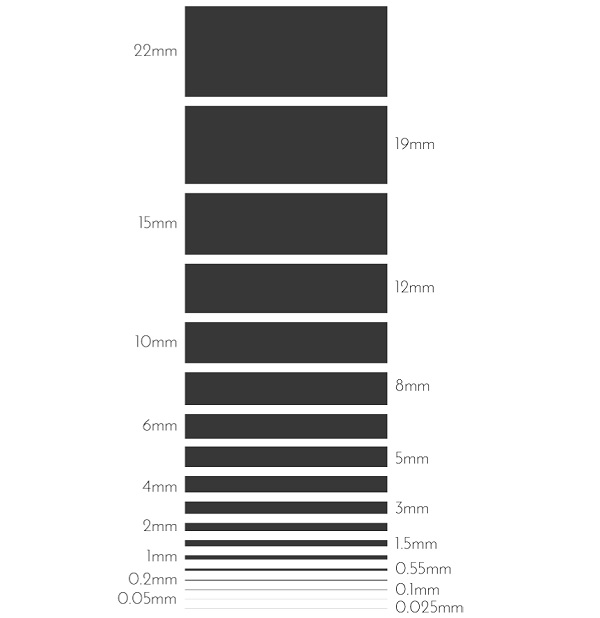
Thin glasses are here defined as those under the thickness of 2 mm, as this is the minimal standard glass thickness of float glass (although thicknesses as thin as 0.1mm can also be achieved by this process). As of ultra-thin glass, these are usually classified as glass under the thickness of 0.1 mm (100μm) (AGC 2011); as for the current date, glasses at the thicknesses of 25 μm (0.025mm) are already being produced.
Figure 1 illustrates a comparison between typical float glass thicknesses (in scale 1:1) until the ultra-thin glass that can be produced.
Although this material may seem like an exclusive material used for particular purposes, it is widespread on smartphones and mobile devices; the evolution of these products in the past decade has pushed the glass industry to produce ever thinner and resistant glass, attending to the necessities of scratch, fall resistance, and low weight.
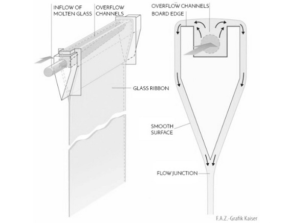
Thin glass material properties depend on its composition; “typical glass types used for thin glass are borosilicate glass, aluminosilicate glass and the well-known float glass” (Albus and Robanus 2015) or soda lime silicate glass. Itcan be produced by the traditional float process, the down-draw process, and the overflow-fusion process (Schneider 2015 and Neugebauer 2015). The last (Figure 3) produces glass with a higher surface quality, as the glass surface does not have contact with any solids during its production.
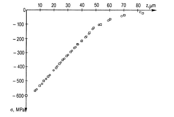
To improve the material properties of thin glass, this material is usually pre-stressed by chemical strengthening, which consists in a process of ion exchanging instead of thermal shock (quenching). The result of this process is a surface compression much higher than that of fully tempered (75Mpa), or heat strengthened (25Mpa) glass, reaching values such as 300 MPa (Schittich, C. et al. 2007). It is important to remark that the typical depth of the compressive layer of this process is very narrow, 25-50 μm (Schneider, J.), and the glass strength is notably reduced in the center of the glass. In the Figure 2, an example of a measurement of a chemically strengthened soda lime glass shows this behavior, the surface compressive stress is of 500 MPa, however at 50 μm deep this value is already lower than 100 MPa.
The minimum radius this material can bend is directly related to its thickness, generally, the thinner the glass, thesmaller the radius it can achieve without breaking. In addition to that, a combination of material properties, production process, and strengthening can make thin glass more resistant to bending stresses, allowing it to bend to smaller radii.
2.1.Current applications in the built environment
Although this material is commonly available in smartphones and other electronic devices, thin glass is still on its first steps in the built environment.
The most advanced application at this time is at the production of high-performance windows, in which thin glass is used in triple and quadruple-glazed windows for the visual and lightweight qualities (MEM4WIN 2012). Another example of the use of this material was in the World Cup of 2014 (AGC 2014). In this event, the player benches were designed using thin glass on the top and back of these elements to provide maximum transparency, weather and impact resistance while reducing reflections.
A different application for this product was also found by one of its leading producers. Corning has developed analternative use for its Gorilla Glass. Due to the impact and scratch resistance of thin glass, together with its optical qualities, this material is currently being used as a protective layer in interior architecture, mainly targeted at elevator’s interiors (Corning 2018). It’s used as an external layer allowing the lamination of panels behind it, which can be exhibited with high optical quality, without being susceptible to damage.
The last built example mentioned here is an experimental study, developed by prof. Jürgen Neugebauer and APG, and realized by SFL Technologies at the GlassTec 2014 in Dusseldorf (Neugebauer 2015). It consists of a movable glass canopy, which can be expanded and contracted in two directions. The appealing aspect of this example is that it shows the adaptability of thin glass, which is bent into a complex geometry and then moved back to its original state.
3. Potential uses for thin glass in the built environment
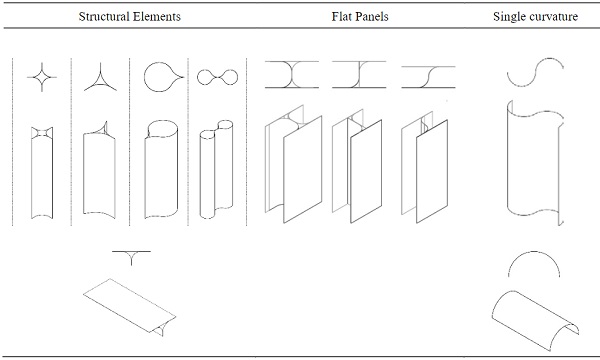
After studying the material properties of thin glass and analysing its current uses in the built environment, additional possible applications were explored in this context. Considering the classification of forms elaborated by Wurm (2007), four main geometry types or applications were selected (Structural elements, flat panels, single radius elements) in which glass is used in the built environment, and then alternatives (Table 1) were explored using the thin glass technology.
In general, thin glass can increase the stiffness of glass elements by adapting its geometry instead of the addition of glass layers, or stiffeners from other materials. An example of this strategy can be applied in glass column design for increasing buckling resistance and in flat panels to increase stiffness without affecting the transparency of a façade. However, the flexibility of this material could also be considered a disadvantage in some cases that depend on its shape for stability; if any part of the surface is deformed due to an impact, the structural integrity could be compromised. As an alternative to that thin glass could be used as a protective layer for other glass elements.
Table 1: Geometric exploration of thin glass in common glass applications. (Ribeiro Silveira 2016)
After exploring different applications, it is clear that the most remarkable characteristic of this material is its flexibility.
From this initial overview and the research on the material properties, it was concluded that an adequate use of thin glass in the built environment would be one that would benefit from its transparency, adaptability, and flexibility.Adaptive façade panels were considered to be the application that best answered to these characteristics, using the potential of the material at the same time as showing its value in a façade.
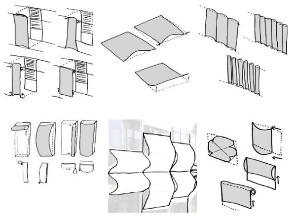
To explore the outcome of using thin glass adaptive panels in a façade, different façade panel types were selected and, for each of them, thin glass alternatives for their current façade components where were sketched and analyzed (Figure 4).
It was then concluded that the most suitable building elements for the development of the study would be on double skin façades, with the thin glass adaptive panel on the outer skin. This strategy allows for the interior spaces of the building to be insulated by the inner skin, while the exterior skin creates the visual identity of the building and can also help on the performance of the building skin, as controlling the ventilation for instance.
The definition of the boundaries of the research also relates to the dimensions of the studied panel. This panel should be of a floor height and a standard width for building-related purposes. The selected panel dimensions to attend to these parameters were 3000 by 1250 mm, using a hypothetical thin glass panel of 3000 by 1750 mm allowing for the geometry exploration of the use of this material.
4. Study on movement and supports
The research followed on simulating the material behavior under bending and the relation between its thickness and bending stresses.
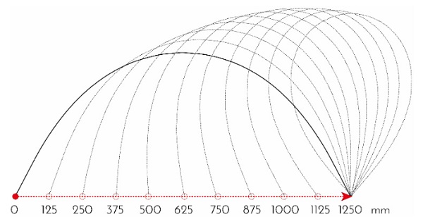
A numerical analysis was made by simulating the movement of one edge of the panel and checking the resulting geometry and stresses generated by the increase of the bending according to different glass thicknesses. Thissimulation was made by moving one of the longer edges of the panel (3000 by 1250 mm) in a 125mm step until it was at the same position of the other one. The boundary conditions were determined by using pinned supports on the two edges, allowing for rotation. This method is illustrated in Figure 5.
The increase of stress by the increasing of bending presented a linear pattern. However, when comparing the pattern of different thicknesses, the stresses increased more from step to step with the increasing of thickness. Thisconclusion is visible in the Figure 6, where the line referring to the stresses in the 2-mm plate is steeper than the others.
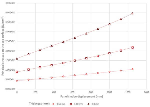
For the development of the studies in this research, it was considered a glass panel with a 1.1 mm thickness, toprovide a balance between bending stresses (allowing for more freedom when exploring different geometries) andthe resistance of the plate to wind loads.
Following this initial understanding of the material, the successive step was to study thin glass in the context of adaptive panels. For a thin glass façade panel to be adaptive, it needs movement. However, this movement is determined by the way this panel is supported and how its supports are designed and positioned.
Therefore, both of these characteristics that allow for adaptiveness were analyzed. First, movement and support alternatives were studied separately; then the relation between was analyzed, showing how the boundary conditions can affect the design and the final geometry of the panel.
It is important to clarify that this analysis had not the objective of covering all possibilities of supports and movement of an adaptive thin glass façade panel. Rather than that, it looks into general design strategies, showing different possibilities and conclusions that could also be adapted to other scenarios.
4.1.Support possibilities
The development of support strategies started by analyzing the aspects to consider when designing supports for a thin glass adaptive façade panel. This analysis resulted in four general technical and aesthetical parameters:
- Protection of the panel edges: due to the cutting of the panel, these are its most vulnerable areas;
- Prevention of stress concentration: essential to be considered due to breakage characteristics of the material;
- Allowance for movement: the supports should not obstruct the movement of the panel, instead, they should enhance it;
- Avoidance of view obstruction: in a context of a glass façade the supports should be positioned in order not to interfere in the views from inside the building.
Based on these parameters and the thin glass alternatives to current building façades presented in Figure 4, different possibilities of supporting a thin glass adaptive façade panel were developed (Figure 7). Not all of them are ideal according to all parameters, the choice between one strategy or another depends on the desired movement and boundary conditions.
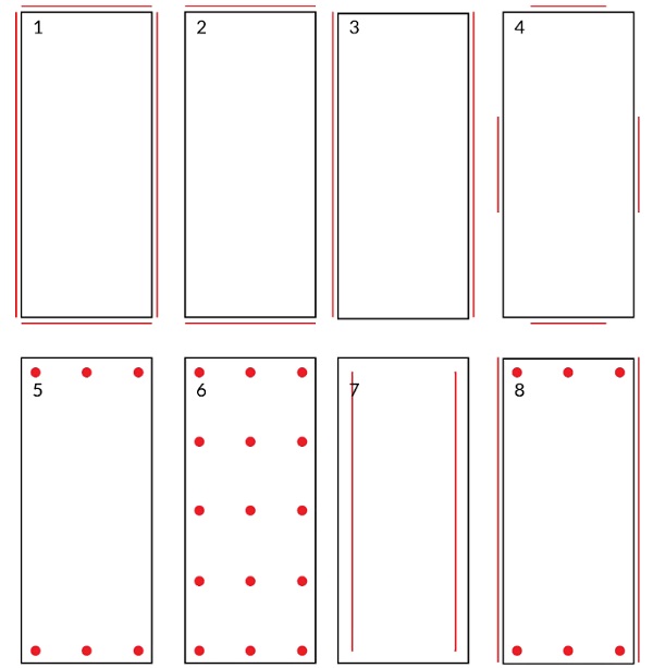
The support solutions can be divided mainly into edge and point supports. The first four options show different ways to use edge supports, these types of support have the advantage of low visual obstruction and also more stiffness to the edges. Options five and six show point supports, which can avoid stresses on the edges, but cause peak stresses and block the views. The last two options show hybrid solutions; option seven shows that linear supports can also be present on the surface of the glass to avoid stresses on the edges, while option 8 shows that these different types of supports can also be combined.
4.2.Movement possibilities
As in the previous analysis, the development of movement strategies of the panel started by looking into general aspects to be considered during the design of the panel, which can be summarized in the following parameters:
- Evidence of movement: making movement evident makes it possible to differentiate thin glass from ordinaryglass, justifying the use of this material;
- Avoidance of multiple actuators: as a façade panel is expected to be reproduced multiple times in a façade, the excessive use of actuators per panel should be avoided;
- Stiffness by geometry: the movement of the panel is directly related to its shape, and to the stiffness obtained from it.
- Double curvature limitation: movements that imply in the double curvature of the panel should be avoided, as the glass has a low strain capacity.
Again, based on these parameters and the solutions presented in Figure 4, different possibilities of moving a thin glass adaptive façade panel were developed (Figure 8). As in the supports analysis, not all of them are ideal regarding all parameters, the choice between them is dependent on the desired final shape and also on the supports design.
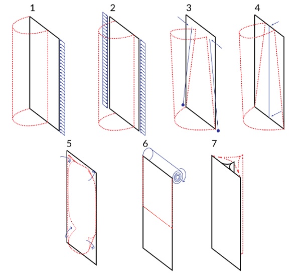
The first three options in Figure 8, regard the movement of the edges of the panel by translation (options 1 and 2), resulting in a cylindrical shape, and rotation (option 3) resulting in a conical geometry. The fourth movement consists of moving the panel by pushing its center in a perpendicular direction, which would result in a cylindrical or conical shape depending if the movement forces on the top and bottom of the panel are equal or not.
The 5th option consists on the bending of the corners of the panel inwards, while the 6th option shows the possibility of rolling the glass pane; in this case the minimum radius of the roll would be defined by the maximum stress allowed by the panel directly related to its thickness (as seen in Figure 6). The last option is a reference to the structural elements geometrical exploration (Table 1) in a façade context, uses the flexibility of the material to deform that geometry and adapt it.
However, all movement possibilities and resulting geometries are very dependent on the supports of the panel. To understand the design of an adaptive thin glass panel, it is not possible to look into movement and support separately, as adaptiveness of the panel is the result of the relation between them.
This relation was investigated by looking into each of the proposed movements (Figure 8) using different support types (Figure 7) and degrees of freedom. The main conclusions of this investigation were:
- Number and type, and degrees of freedom of supports can determine the final geometry of the panel;
- Insufficient degrees of freedom on the supports generally leads to stress concentration;
- Excessive degrees of freedom on the supports generally leads to excess of complexity on design or unpredictability;
- The suitable type of support and degrees of freedom depends on the desired movement and geometry of the panel.
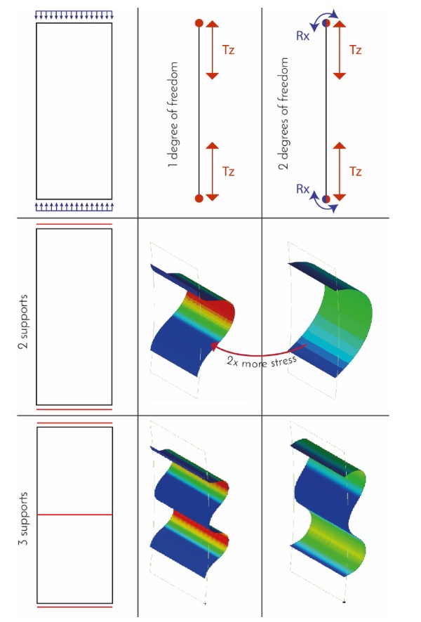
In Figure 9 one of the developed analysis is presented as an example of this investigation, which clearlydemonstrates some of the conclusions listed above.
This example shows a movement based on the translation of the two shorter edges of the panel, comparing the use of two and three supports allowing for one or two degrees of freedom. It is possible to see that the stress and bending moment varies according to the degrees of freedom of the supports. In this case, the stresses were calculated as two times higher if the rotation of the edges is not allowed. It is also very interesting to see that by the addition ofone support the geometry assumes a very different configuration for the same movement.
5. Design
5.1.Potential design strategies
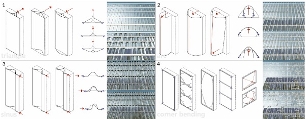
The following step of the study was the development of an example of a thin glass adaptive façade panel. After the analysis presented on item 4, it was possible to better understand the potential use of thin glass in a façade panel.Based on this analysis and on the design parameters developed for supporting and moving this façade panel, four potential design strategies were developed (Figure 10).
The first solution was based on the structural elements geometrical exploration (Table 1); this concept consists of three layers of thin glass laminated together forming a triangular shape. In this way, by pushing one of the edges, it is possible to make a flat and stiff thin glass panel, which is the initial position of the panel. To allow for its movement this same edge is pushed backward or forward, making the other edges move in the direction of each other, opening both sides of the panel.
The second design strategy consists of having a thin glass panel which is moved by a vertical bar that pushes the glass pane outwards increasing its curvature.
The glass is connected to a frame by four pinned supports, which can move horizontally along the supporting frame. According to the movement of the bar, the supporting points translate on the x-direction opening or closing the panel according to the necessities of the building. As the bar is supported by two different actuators, it can assume inclined positions, allowing for different curvatures in the top and bottom layer of the glass, increasing the stiffness of the surface. Also, the bar works as a support against wind loads, avoiding the buckling of the panel.
The third option consists of moving the panel by translating one of its long edges, and using three supports; theresult is a series of sinus shapes. This panel would be moved by a single actuator in one of the sides of the glass panel; forcing the panel to buckle. As the panel is attached to its frame in specific points, this movement generates the sinus shape. These support points also translate together with the glass panel as it is pushed by the actuator, keeping the controlled buckling behavior and increasing the stiffness of the panel.
The fourth and last potential design strategy consists of a flat panel that is adapted by pulling its corners inwards,creating curvature in these specific areas, stiffening the panel.
This panel is supported by its four edges, but its extremities are left free so that the corners can rotate inwards. In this case, the actuator would be placed in the middle of the panel, connected to each of the edges by cables; which are then pulled, bringing the edges of the panel inwards and allowing for its movement.
For the selection of which of these strategies would be adequate for the development of the research they were compared according to the following criteria and methods:
- Transparency: as a glass façade panel, one of its primary functions is to create an invisible barrier between the interior and exterior environment. This was evaluated by comparing interior visualizations of the panel;
- Stiffness: a thin glass façade panel needs to be stiff to prevent vibration, which can cause noise and discomfort to the user of the building. To determine the stiffness of each panel, numerical simulations of each panel were developed, in its initial and bent states;
- Adaptiveness: besides creating a visual effect, it is interesting that the adaptiveness of the panel can enhance the performance of the façade in other aspects. In the context of this research, the technical purpose of adapting the shape of the panel would be of ventilating the façade. For the visual effect, external visualizations were developed, as for the ventilation, the openable surface of each panel was compared to the others.
- Feasibility: it is important to analyze if the detailing of the design strategy is feasible, considering its movement, supports, actuators, and production.
By comparing the four potential design strategies, it was identified that according to the developed criteria the second strategy, the central bar movement, was the one selected for further development. This design proposal, showed a satisfactory balance between the different criteria, with main advantages being its transparency, visual effect and feasibility. However, the stiffness of the panel should be improved, as the choice for punctual supports led to the high concentration of stresses and unexpected deformation of the desired geometry.
5.2.Design example
After analyzing the selected design strategy, the further development of the design example was initiated. The first step was to analyze how the selected design proposal could be improved.
The first improvement was on the type of supports. On the analysis of the relation between movement and supports a comparison between point supports and edge supports for a similar panel was developed. There, the edge supports solution showed an overall better result regarding the stiffness of the panel. Therefore, the four punctual supports were substituted for two edge supports along the long edges of the panel.
The second change was on the glass plate size and thickness (1750mm and 1.1mm respectively as described in previous items 3.1 and 4). Initial numerical simulation analysis showed that the calculated stresses on the glass under a low wind pressure (0.5kN/m²) were already too high, reaching 500N/mm² if the panel was bent asymmetrically (Table 3). Therefore, it was decided to increase the thickness of the panel to 2mm, however, by just increasing the thickness of the panel the initial stresses would become too high. Therefore, it is also necessary to change the width of the glass panel, reducing it to increase the initial bending radius and decrease the stresses generated by it. Thus, the selected final configuration of the glass plate for the design example was a 2mm thick with the dimensions of 1500x3000mm.
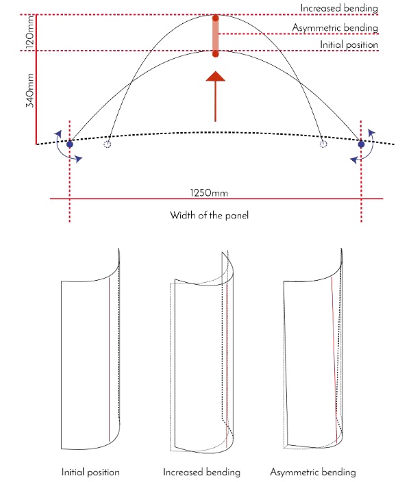
Table 3: Maximum top surface principal stresses in N/mm² according to wind pressure and position of the panel. Glass plate characteristics: thickness: 1.1 mm / dimensions: 1750 x 3000 mm
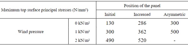
This new configuration (Figure 11) was then reanalyzed in a numerical simulation considering the bending stresses for the three positions of the panel (initial, increased and asymmetric) under wind pressures up to 2kN/m² from different directions. The results are presented in tables 3 and 4.
Table 4: Maximum top surface principal stresses in N/mm² according to wind pressure and position of the panel. Glass plate characteristics: thickness: 2.0 mm / dimensions: 1500 x 3000 mm
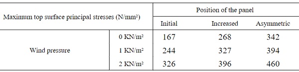
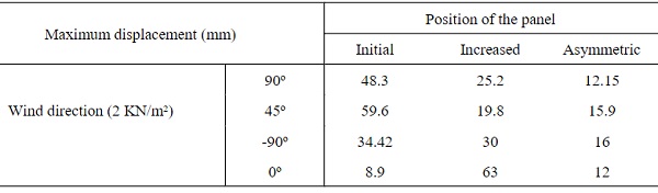
Table 5: Maximum displacement in mm according to wind pressure direction and position of the panel. Glass plate characteristics: thickness: 2.0 mm / dimensions: 1500 x 3000 mm
Even though the initial stresses on the reviewed panel are higher, it is possible to see that there is a significant reduction of stresses under wind load, up to 33% when the panel is on its initial position.
Also, the deformation of the panel is much lower in this new configuration. When loaded with a perpendicular wind pressure of 1 kN/m² on the initial position the maximum displacement of the panel is of 48.3mm; under the same boundary conditions, the previous configuration had a deformation of 197mm.
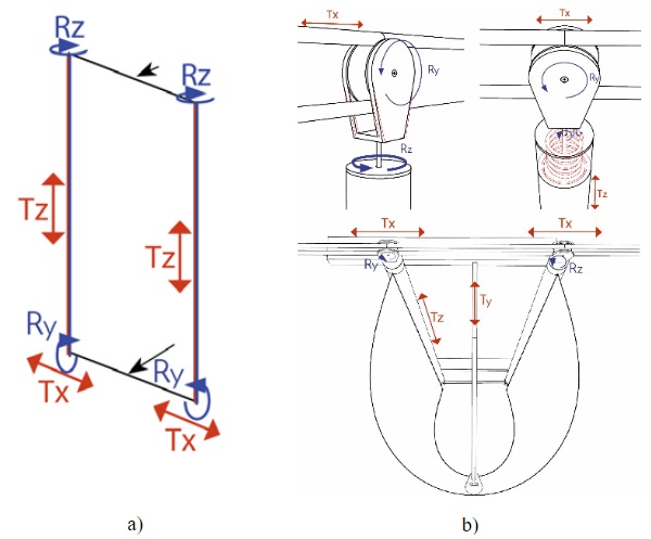
After analyzing the stresses on the panel, the next step in the development of the design example was its detailing. The process started by looking into the degrees of freedom required for the movement of the panel; in total four degrees of freedom needed to be addressed (Figure 12a).
The solution to this challenge (Figure 12b) was on using the same component for all corners of the panel. A single wheel that can also act as a pendulum allows for the translation the x-axis, and the rotation around the y-axis. The wheel is fixed to a component which is then connected to the other parts of the panel by an elevator bolt, which is integrated with a spring allowing for the translation of the panel on the z-axis. In addition, the edge profile of the panel can rotate around the bolt, allowing for the last necessary degree of freedom.
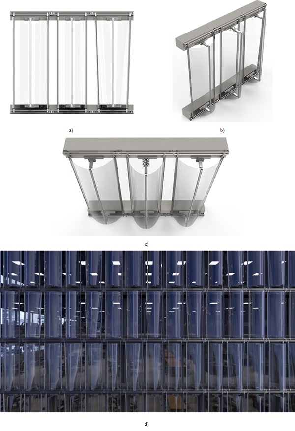
Based on the detailing concept each element of the panel was developed, making it possible to develop a design example of a thin glass adaptive panel. This example was elaborated as generic panel (meaning that not implemented in a specific building) with the function of an adaptive double skin façade panel. In Figure 13 it is possible to see the appearance of this panel and a visualization of it integrated into an office building.
5.3.Mock-up
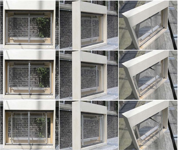
The final step of the research was a construction of a mock-up using thin glass as a proof of concept (Figure 14).
The model was developed using a 2mm thin glass plate of 500 x 700 mm and two chain drive actuator which had a maximum stroke length of 250mm. The designed connection was simulated in the following way:
The glass was supported by two edges, using aluminum profiles which were connected to the top and bottom steel tubes by a combination of a bolt fixed to a sphere (which was constrained inside the tube). The actuators were fixed to the model frame and pushed a vertical aluminum bar which was attached to the glass. When the actuators pushed the bar, the edges were free to translate and rotate around the supports.
The end result of the mock-up was very satisfactory. It was possible to use the full stroke length of the actuator, achieving a minimum bending radius of 106 mm and a maximum calculated bending stress of 424MPa.
6. Conclusions
The safe use of thin glass in façades is still dependent on more research and tests. Suggested topics would be on the breakage behavior and lamination (and delamination due to movement) of this material and its integration with other materials, such as bimetals for instance.
Nevertheless, the development of this research contributes to the growth of knowledge over the use of this material on the façades context. This study shows that the use of a thin glass adaptive panels in a façade can achieve interesting results regarding visual effect, ventilation and dead load reduction. Also, it challenges the concept of glass as a static material, opening new possibilities for the use of this material.
Acknowledgements
The authors would like to thank Peter Eigenraam for his contribution as a mentor to the MSc study here presented.Likewise, express their gratitude to AGC for providing the thin glass for this study and D+H mechatronic and DWS Solutions for providing the chain drive actuators for the physical model. Also, the European COST Action TU1403 Adaptive Façades is acknowledged for providing a research network.
References
AGC: 2014 FIFA World Cup Brazil™ Glass Roof for Player Benches Unveiled (2014) http://www.agc.com/en/news/pdf/20140424e_1.pdf. Accessed 14 January 2018.
AGC: AGC Develops World’s Thinnest Sheet Float Glass at Just 0.1 mm. Press release (2011)
ALBUS, J. ROBANUS, S.: Glass in Architecture - Future developments. Detail magazine - Glass construction, pp. 168 – 174. Vol. 2 (2015)
CORNING: Elevators go light, modern and durable with Corning Gorilla Glass (2018) https://www.corning.com/worldwide/en/innovation/corning-emerging-innovations/elevators_architecture.html. Accessed 14 January 2018.
GY, R.: Ion exchange for glass strengthening. Materials Science and Engineering: B 149.2: pp 159- 165. (2008)
KUEFFNER, G.: Bruchfest und hart müssen Scheiben sein (2012). http://www.faz.net/aktuell/technik-motor/smartphone-displays-bruchfest-und-hart-muessen-scheiben-sein-11712180.html#aufmacherBildJumpTarget. Accessed 30 December 2015.
MEM4WIN Technologies explored in MEM4WIN project (2012). http://mem4win.eu/index.php?id=86. Accessed 14 January 2018.
NEUGEBAUER, J.: A movable canopy. Proceedings of the International Conference on Building Envelope Design and Technology. Graz. Advanced Building Skins. pp.324. (2015)
RIBEIRO SILVEIRA R.: 2016 Flexible transparency: A study on thin glass adaptive façade panels. Master's thesis, Delft University of Technology (2016)
SCHNEIDER, J.: Thin Glasses - A future envelope? The Future Envelope 9 – Conference on the Building Envelope. pp 54 -69 (2015)
SCHITTICH, C. et al.: Glass construction manual. Birkhauser Architecture, 2007
WURM, J.: Glass structures: design and construction of self-supporting skins. Walter de Gruyter. 2007


