.")
Source:
Challenging Glass 7
Conference on Architectural and Structural Applications of Glass
Belis, Bos & Louter (Eds.), Ghent University, September 2020.
Copyright © with the authors. All rights reserved.
ISBN 978-94-6366-296-3, https://doi.org/10.7480/cgc.7.4547
Authors:
Özhan Topcu - seele GmbH
Vladimir Marinov - Define Engineers

Thin glass offers a promising prospect for lightweight façades with reduced use of raw materials, also opening up entirely new perspectives for architectural expression with its excellent optical quality as well as its high flexibility. The realisation of projects featuring thin glass as a structural element is so far limited due to several challenges led by structural issues mainly induced by the product's low stiffness.
This paper attempts to bypass this issue by exploring the possibilities of the structural application of thin glass as a membrane element using examples of all-glass projects from the past as well as research project sconducted in the present. The use of thin glass as a compressive member is impractical since the risk of buckling poses a greater threat than stress exceedance.
As an alternative, its application as a tensile member is proposed, supported by examples from academic and industrial research projects. In this context, a new type of glass support is introduced, enabling a moment-free load transfer into the glass.
1. Introduction
The desire for transparency in buildings in contemporary architecture where opaque building elements are increasingly being replaced by transparent elements makes the use of glass as a construction material more and more desirable. On top of that, the realisation of glass constructions is becoming increasingly challenging together with the growth of expectations, which is demonstrated by numerous existing all-glass projects around the world.
The rapid development of research and production techniques has a decisive impact to the increased use of this material and is undoubtedly one of the key factors in this positive trend. This statement is supported by Baum (2007) with the following sentence: “Initially, it was not the architects who took architecture into the modern age, but rather engineers and planners from so called non-artistic disciplines“.
Today, the aforementioned development of production techniques allows us to produce glass with thicknesses as little as 25 μm (Schott AG, 2019). Thin glass in this context, opens entirely new perspectives in glass design for architecture but it also comes with challenges, which need to be overcome. A number of projects have been realised in the past and present that can serve as a guide for the implementation of this relatively novel product.
2. Thin Glass in Practice
In general, glasses of a thickness of 2 mm or less fall into the category of thin glass. While thin-or ultra-thing lass is commonly applied in other industries such as the electronics industry, standard glass thicknesses used in architecture normally range from 2 to 12 mm. Both, the possibilities as well as the challenges thin glass entails, if it is to be implemented into the built environment, are described in this chapter.
2.1. Advantages and Possibilities
In comparison to regular glass, thin glass stands out with its reduced use of raw materials and its low weight due to its lower thickness at same density. These aspects do not only offer the potential for an economic advantage but also contribute to the sustainability of the building in general due to the reduction in the use of raw materials. This does not only apply to the glass itself but to the entire building, as a low glass weight also reduces the weight acting on the supporting structure.
A further aspect worth mentioning is the higher flexibility of thin glass and its excellent optical quality in comparison to glass of conventional thicknesses. Instead of considering the flexibility as a disadvantage, it can be regarded as an opportunity to open the way for the design of more transparent and optically appealing structures. If complex shapes are to be created with glass, they are restricted either due to potentially high costs of hot bending processes or due to technical limitations, such as too large minimum bending radii of cold formed glasses (Topcu 2017).
With a reduced thickness, smaller bending radii with the cold bending method are made possible. Several studies conducted at TU Delft suggest potential applications of adaptable façade elements in combination with thin glass. Some include bending the glass for purposes such as regulating the air inlet to the interior, adjusting its shape according to the intensity of the wind load, or adjusting the position of PV-cells that are integrated to the glass surface according to the angle of incidence of the sunlight (Louter et al. 2018).
Apart from academic research projects, also numerous industrial research projects have been conducted involving cold bending of thin glass, which demonstrate the extent of how much thin glass can be deformed and what possibilities this property brings about.
A research conducted by seele in 2012 studied the minimum achievable radius of thin glass that is cold bent during the lamination process (Figure 01). The test was performed with two chemically strengthened glass sheets with a thickness of 1 mm each and a 0.89 mm SGP-interlayer. The sample was first modelled using an FE-model to determine the probable minimum bending radius, which was then successfully implemented in the bending test. The bending was performed using a 3D-printed mould with a radius of 300 mm. The glass radius increased to a final value of 450 mm after relaxation, which is not thinkable with glasses of regular thicknesses (Kloker 2012).
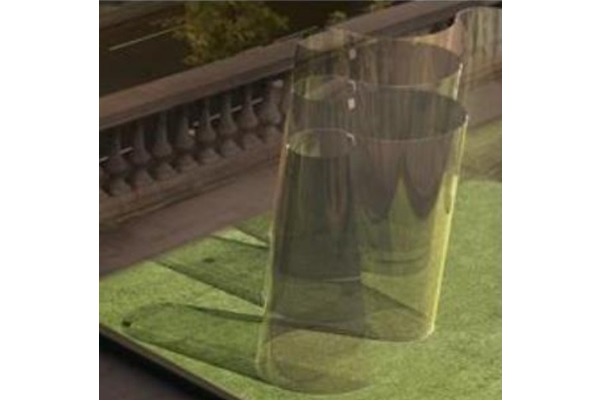
A further research showcasing the bendability of thin glass is the flowing glass sculpture proposed and designed by Carpenter / Lowings Architecture & Design and Eckersley O’Callaghan Ltd (Figure 02). This example shows a frameless thin glass sculpture, where the cold bending is accomplished with point fixings at the corners of the chemically strenghtened glass elements. Due to the cold bending process, less optical distortions are created in comparison to hot-bent glass. Another effect that is gained with the resulting shape is stiffness through geometry, which allows the glass to stand on its own, without the help of an additional substructure.

2.2. Limiting Factors
As much as thin glass is a promising prospect for the future, it has not been implemented in any project functioning as a structural member to this day. This can be led back to a number of reasons. This paper solely focuses on the limiting factors from a structural point of view.
The first challenge to overcome is the low bending stiffness of the element, as well as its high susceptibility to buckling, as would be the case in every material with a low thickness. In case of glass however, its brittle behaviour increases the risk of serious consequences in case of failure, which requires additional attention.
Another aspect to focus on is the design of the support concept. The reason therefore is that common glass support concepts, such as setting blocks or toggle systems, are developed for plates subjected to out-of-plane loading and are not ideal for the use with thin glass. Thus, a rethinking is required if loads are to be transferred effectively through the thin glass element.
3. Glass as a Membrane Element
3.1. Use of Glass as a Membrane Element
Among the aforementioned challenges we are facing, the lack of stiffness is undoubtedly the one that requires the most attention, as the structural conceptis completely dependent on it. Conventionally, the application of glass in architecture is limited to that of a plate serving as a building envelope and in some cases as a barrier. Since plates are subjected to bending, thin glass does not offer much potential in this manner due to its lack of stiffness as a result of its low thickness. A possible and more effective way of making use of this products’ full potentialis to apply membrane theory.
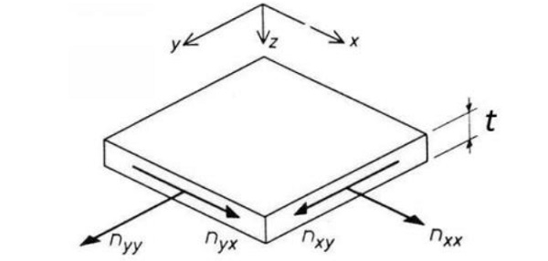
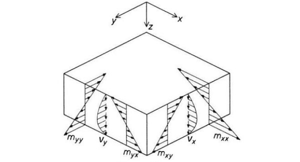
Membrane theory describes the state of a structure in which loads are mainly transferred in form of normal forces, where as bending moments are small enough to be negligible. It has proved itself over time as a very effective method to transfer loads with minimum use of material. The advantage of this effect over a plate is that stresses are evenly distributed over the entire cross-section. Unlike in the case of plates, stress peaks or uneven stress distribution within the cross-section are avoided and the material of the structure can be utilised to its full capacity (Figure 3 and 4).
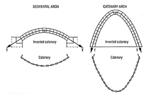
Common geometries that allow membrane behaviour are arches, shells, domes and barrels amongst other shapes. All these geometries are based on the principle of the catenary curve: the form that occurs when a chain is held loosely on both ends. If the hanging chain is assumed to beglued at the connection points of each link and is inverted, the resulting geometry corresponds to that of the line of thrust (Figure 5).
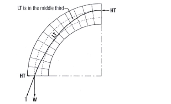
The line of thrust (LT) is an imaginary line through which the normal forces flow in a structure. It comprises two forces: the weight of the structure (W) and the horizontal thrust (HT). The resultant force of these two is the thrust (T), acting inthe direction of the line of thrust (Figure 6).
In an ideal arch, the normal forces run through its axis, meaning that this particular shape will provide the greatest stability in case of self-weight. In comparison, in a barrel or a dome, the thrust line will slightly deviate from the centre of the cross-section. If the thrust line moves away from the centre, tensile forces will be induced. The structure will however remain stable as long as the thrust line remains inside the middle third of the cross-section (Dutton 2013).
The geometry of a thin shell can be identified with a similar concept of a hanging model. This method is also described as structural form finding.The imaginary chain is then replaced by a cloth, which is held at each support. The shape that occurs due to the cloths self-weight forms the base of common shell structures comprising monolithic domes, grid shells or saddle roofs.
The shape of the arch is controlled by the line of thrust, which corresponds to the catenary line. For external loads such as wind, which can be asymmetrical, a further optimization of the geometry is required. Unlike the arch, the shape of the thin shell is not required to be adapted to the load. While the arch can only transfer loads without bending moments if its shape is adjusted to the load, the shell has the ability to carry loads moment-free, as long as it is supported in-plane of the shell and concentrated loads are avoided (Schober 2015).
3.2. Use of Glass as a Compressive Member
seele has realised all-glass projects in the past, in which glass acts as a compressive or in-plane shear member.These projects highlight that it was possible to create economically efficient all-glass structures even with the technology of more than 20 years ago.
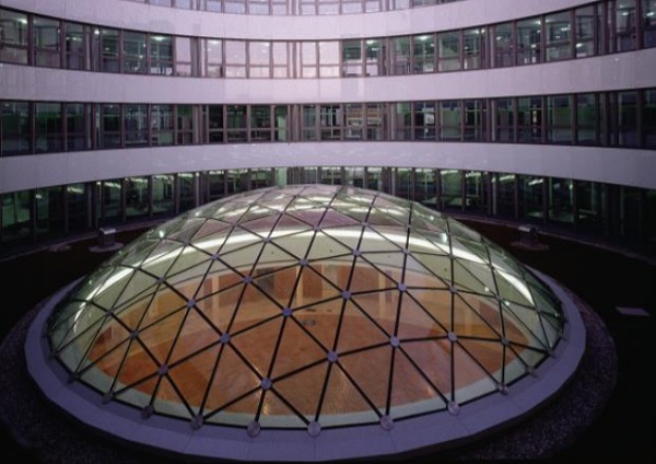
The first project is a shell structure consisting of triangle-shaped insulating glass units (Figure 7). The glass dome features a diameter of 12.5 m and a rise of 2.5 m. Completed in 1997, the dome introduced a novel type of construction, where the load bearing characteristics of glass was utilised, instead of relying on the structural capabilities of steel. The idea behind the concept was to create a structure as lightweight and transparent as possible. The dome solely consists of glass elements, which are subjected to compressive forces.
These forces are a result of the self-weight of the structure as well as the pre-stressing caused by the cable-net spanning between each node along the joints. A key factor for the development of this structure was the material characteristic of glass, being able to transfer larger compressive forces than tensile forces. While this method proved effective, the risk of buckling that comes with the slenderness of the structure sets a limit to the possibilities that can be accomplished with a glass dome (Ludwig & Weiler 2013).
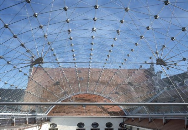
The all-glass barrel-vault roof of the Maximilianmuseum, completed in 2002, forms a self-supporting structure over a historical courtyard measuring 37m x 14m with a total of 527 glass panes (Figure 8). The only component complementing this all-glass shell is a tubular frame that is needed to define the edges of the barrel vault. The single-curvature shell structure forming the barrel vault enabled economic prefabrication of identical panes. Compressive stresses are transferred to the structure at the nodes.
To do this, each pane is supported on the node plate via stainless steel caps fitted to the corners. A pin with adjusting screws in the centre of the node is used to position the plate to create a structural connection with the steel caps. Each pane is made of laminated safety glass consisting of two plies of 12 mm heat-strengthened glass and measures 1.16 m x 0.95 m (seele GmbH 2020).
Both of the mentioned projects display an example with the glass acting as a compression member. However since a shell structure requires a minimum thickness to prevent compressive buckling, this concept is not ideal for the application of thin glass. A possible solution to overcome this obstacle is to invert the structure back to its original orientation under its self-weight.
This way, the glass will be subjected to tensile stress. While, as mentioned in the case study of the Weltbild Dome, glass is more effective under compression compared to tension, buckling poses a greater risk for thin glass than failure due to stress exceedance. Therefore, loads are transferred more effectively in form of tensile forces since the destabilizing effect of compressive forces is avoided, thus eliminating the risk of buckling.
Numerous researches are being conducted to study the capabilities of glass when used as a tensile member. Their findings are crucial to give an idea of how much further thin glass structures can go in the architecture branch.
3.3. Use of Glass as a Tensile Member
In this chapter, two exhibits are introduced to showcase the abilities of glass subjected to tension.
The research conducted by TU Darmstadt shows an example of the already existing concept of a flexible cable net structure inspired by the Munich Olympic Park roof by Frei Otto. With the roof cover being replaced by thin glass, the structure allows for more transparency and remains lightweight at the same time. Thereby, the cable net dictates the shape of the structure according to the pre-stressing grade of each cable, while the glass acts as a form-following cover making up a transparent weatherproof roof structure as well as transferring loads (Figure 9).
Due to the large deformation that occurs in the glass in relation to its thickness, the assumption of linear plate theory does no longer apply and geometrically non-linear effects need to be considered for an accurate calculation. The glass is subjected to a combination of bending-and membrane forces. In order to ensure a continuous structure with a smooth transition between each glass element, the elements are linearly supported with continuous clamping bars (Figure 10, Peters et al. 2019).
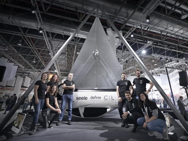
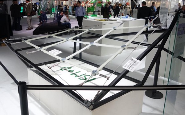
The concept of using thin glass as a structural membrane is perhaps most effectively showcased by the project ‘Gravity’ at the Glass Technology Live section in 2018. Starting off with the idea of having thin membrane in tension meant an innovative way of transferring the load needed to be devised. Around that time bonding systems like TSSA from Dow have begun to suggest different ways of getting forces in and out of glass surfaces: previously with thicker glass systems minimisation of fixings meant development of point fixings, which focus forces at the points.
Thin glass, with its low bearing capacity, suggests that a more distributed fixing system would be necessary, and a strip fixing was something that was developed for this project. In a car windscreen for example, thin glass suggests a continuous perimeter fixing rather than point attachments. This has an aesthetic merit, which has been a direction of exploration by architects and engineers for a while.
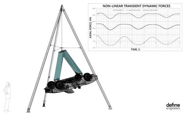
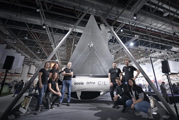
The exhibit comprises two glass panels made up of two sheets of 2 mm thin glass laminated with SGP and bonded to stainless steel edge strips, which are suspended from a tripod structure. The assembly is holding 1.5 tonne swinging car close over a podium. The glass sheets are 1m x 2m, composed of two heat-strengthened laminated glass panes. The glass bonding detail is one-sided relying entirely on the adhesive connection to transfer the loads.
The swinging of the car mass was simulated by Define Engineers using non-linear transient dynamic finite element analysis. The suspension point at the top of the glass allows the car to spin 360 degrees and to swing in any direction by 15 degrees from vertical, all hanging from a 9.5mm diameter high strength steel rod. This was modelled in the analysis as a pendulum with initial displacement equal to the maximum angle of swing and minimal damping of 5%.
The dynamically amplified tension force in the system (Figure 11) was used to design all components of the exhibit. The non-linear effect of the glass in tension (15kN) counters the bending, which might have otherwise occurred due to self-weight of the glass or any other later load, much like a string in tension, which keeps straight and can resist lateral loads. The result of using permanent tension in the glass was perfectly straight glass panels adding to the dramatic effect of the exhibit.
The hangers and all brackets were carefully designed to avoid out-of-plane forces bending the glass. This is achieved by using an offset steel bracket (Figure 12) which introduces moment in the steelwork but the line of reaction is aligned with the centerline of the glass. That results in zero effective bending in the glass from the tension force.
Further to that,the pivot at the top has been specifically designed to allow maximum movement and minimum restraint to reduce twisting forces in the glass panels. In summary, in order to maintain the membrane only loading in the glass, all the attention was put in the detailing of the system to release the glass as much as possible while maintaining a stable system.
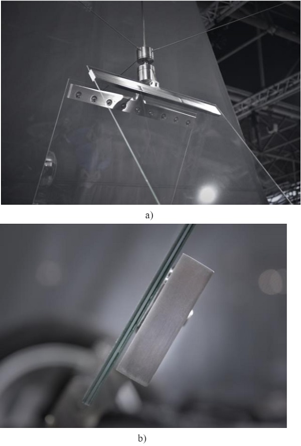
The heat-strengthened glass is bonded using Dow TSSA to stainless strips within the hanger details, which are in turn connected to the car, and the specially designed and fabricated suspension detail at the top. The laminated glass uses SGP as an interlayer, and the glass, being heat-strengthened, has a breakage pattern, which allows transfer of loads to the back-up glass sheet, through the interlayer. Note that the detail is one-sided to reveal the transparency of the fixing detail and preserve the clarity of the front face of the glass. This suggests how it could be presented in an architectural context for real projects.
A key feature of project is the transparent connection between the glass and the stainless steel brackets made with The Dow Chemical Company DOWSIL™ Transparent Structural Silicone Adhesive (TSSA). The permanent stress in the TSSA layer, estimated at about 0.6 N/mm², is further increased by the dynamic effects of the swinging car to about 0.7 N/mm². The final exhibit in the Glass Technology Live section is shown in Figure 13.
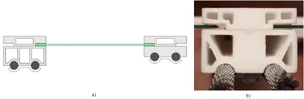
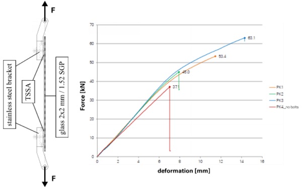
seele carried out structural performance tests to confirm the TSSA reliability utilising samples of thin glass with a size of 400 mm x 600 mm provided by Glaston Corporation. The test TSSA bonding area of 300 mm x 40 mm had to transfer a permanent load of 4.5 kN resulting in local peak stresses of about 0.6 N/mm².
For the short-term experiments, the force was increased until the failure of either the glass or the TSSA. The maximum achieved tensile force reached a mean value of 53.8 kN for the first three samples (Figure 14). The fourth sample (PK4) was subjected to additional bending on purpose and is therefore not included in the average value.
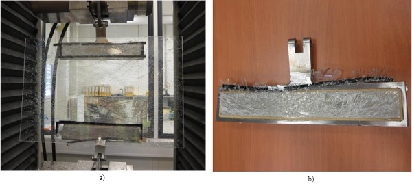
Upon reaching the maximum force, the failure occurred at the entire laminate. The entire TSSA surface was covered with glass fragments, showing that the adhesive layer was still intact after reaching the maximum force (Figure 15).
The long-term experiments were performed under the structurally required force for one week and the same force increased by 50% for another week. The samples were able to withstand the loads without any visible alterations. Subsequently, the glass plies were fractured in order to test the residual capacity of the laminate. Despite the propagation of single cracks, a complete failure did not occur.
4. Future Application and Potential
Thin glass is a promising material for creating more lightweight, transparent and optically appealing structures with the application of traditional engineering design approaches in combination with innovative materials that require innovative solutions.
The aim of this paper is to present the advantages this novel product could entail with its unique properties, such as its low weight or its high flexibility. In contrast, some of the challenges and the limiting factors are mentioned, demonstrating where the difficulties lie in implementing thin glass into the built environment as well as the limits that are set due to the intrinsic nature of the material.
Focusing on the structural aspects, this paper deals with the issues of stiffness and load introduction. As a solution, the use of glass as a membrane element and a connection detail with TSSA are suggested respectively, both supported by examples from projects realised in the past and by exhibits from the present.
The results of this paper show that at the current state of technology, we possess the general understanding on two crucial aspects: 1) The functioning of thin glass in the structural context and how to make use of its full potential. When applied as a membrane element, the glass offers more potential as a structural member, as stress is distributed evenly. 2) The load introduction into the glass in a way that bending moments are avoided and the glass can function as a membrane.
With the acquired knowledge at hand, we are now facing the challenge to come up with further ideas to bring this vision closer towards an application in future buildings. Nonetheless, the insights gained so far from previous experiences prove the potential of the product and can serve as an encouragement for further research in this field.
5. Acknowledgements
The authors gratefully acknowledge Martien Teich for his assistance and valuable input especially during the conceptual stages of the paper and Timon Peters for providing information on the Thin Glass Cable Net Structure.
6.References
Baum, M.: Ulice na konci světa -o architektuře a jiných věcech (1st ed.), Prague (2007)
Borgart, A: Structural geometry. Presentation, Delft(2016)
Drass, M: Cable net structure. Presentation, Darmstadt(2019)
Dutton, A: Analysis of domes. Weebly. https://concretedomestructures.weebly.com/analysis-of-domes.html.(2013). Accessed 04 January 2020
Kloker, S: Kurzbericht 2012-05-22, Laminationsbiegen Dünnglas Kreistonne 450 mm, seele sedak (2012)
Lambert, H., O’Callaghan J.: Ultra-thin high strength glass research and potential applications. Glass Performance Days (2013)
Louter, C.,Akilo, M.A.,Miri, B., Neeskens, T.,Ribeiro Silveira, R., Topcu, Ö.,Van der Weide, I.,Zha, C.,Bilow, M.,Turrin, M.,Klein, T.,O’Callaghan, J.: Adaptive and composite thin glass concepts for architectural applications. Heron 63, H. 1-2, S. 199-218(2018). http://heronjournal.nl/63-12/9.html
Ludwig, J.J., Weiler, H.-U.: Innovative Tragstrukturen aus Glas Ganzglaskugelkalotte –Weltbildkuppel in Augsburg. Stahlbau (2013). doi:10.1002/stab.199801020
Peters, T., Jaschke, S., Schneider, J.: Thin glass in membrane-like structures –applications, modelling and testing. IASS (2019)
Schober, H: Geometrie-Prinzipien für wirtschaftliche und effiziente Schalentragwerke. Bautechnik (2002). doi:10.1002/bate.200200030
Schott AG: Ultra-thin glass. https://www.schott.com/advanced_optics/english/products/wafers-and-thin-glass/glass-wafer-and-substrates/ultra-thin-glass/index.html (2019). Accessed 05 December 2019
seele Gmbh: Maximilianmuseum, https://seele.com/references/maximilianmuseum/ (2020). Accessed 16 January 2020
Topcu, Ö.: Kinetic thin glass façade: a study on the feasibility of a water-and airtight kinetic façade with a bending-active thin glass element. Master’s thesis, Delft University of Technology (2017)