First presented at GPD 2017
This creates special demands on appropriate design of glass units and frame members as well as on the elastic and load-bearing bonding joints in Structural Sealant Glazing applications.
Depending on the approach of producing and installing these units as well as the geometrical boundary conditions, the structural silicone joints are affected by additional permanent load reactions and joint movements next to regular loading. Due to the warped or curved shape of the units, significant changes in load distribution, load sharing and stiffness can result and even load peaks in the elastic silicone joints can arise.
This paper summarizes technical requirements and engineering rules as well as design aspects enabling appropriate design and calculation of structural silicone joints in cold-bent SSG units. Reflecting a reliable safety concept and the expected life cycle of these load-bearing bonding joints is part of the approach.
1. Introduction
The demand of emulating nature’s complex and flowing layout by using curved or even biomorphic design combined with transparent panels and valuable surfaces is an increasing trend replacing conventional straight-lined and sharp-edged geometry in architectural design.
While traditional design limits the architectural freedom as well as the value of recognition and building identity, curvilinear design offers an unlimited variety of custom-made and nonrecurring building shapes. Designs supported by advanced planning processes and computer-aided tools, which had been reserved for automotive industry, have been transferring to buildings and facades.
Considering that sophisticated designs of typical industrial products are implemented to a serial production using complex and dedicated tools, it’s the façade engineer’s and manufacturer’s challenge to properly realize custom-made and mostly nonrecurring shapes within the given economical, technical and regulative restrictions and within acceptable timeframe.
Based on the fact that facades as face and skin of a building have to comply with functional, protective and architectural demands, glass and glazed units as a main part of the envelope have to comply with these demands, too. That means, glass units and their restraints have to fit curvilinear designs, what pushes the demand on curved and warped single glass, laminated glass as well as insulating glass units replacing more and more flat and polygonally installed or even cylindrically shaped glass units.
2. Curved Glass Elements Manufacturing
Curved architectural glass can be manufactured in the façade markets according to three main methods.
• Hot bending
During thermal shaping of glass, a variety of cylindrical and spherical as well as asymmetrical and irregular bending shapes with smaller and larger bending radii can be achieved within the technical limits. The advantage lies in the exact and permanent setting of the required shape in the manufacturing process. The pre-sized float glass sheets are heated to just over the transformation temperature.
Based on the desired geometry and manufacturing processes, the softened glass either can settle in the prefabricated and fire-resistant mold (bending by gravity) by its own weight or is shaped through mechanical molding. The resulting glass strength, fracture pattern an tolerances in the finished state are largely controlled by the cooling process itself. Glass coatings can’t be applied on the shaped glass surfaces, after hot-bending. Due to the manufacturing process, required reflective of low-e coatings must be thermally stable and suitable for tempering.
PVB interlayers, applied between two bent glass lites after the hot-bending procedure, must be chosen in respect of thickness and material properties so that tolerance between the bent lites can be accommodated without constraining stresses. The assembling of the insulated glass unit or its connection to the façade element must also be stressfree. But especially for heavily curved units increased climatic effects, affecting the hermetically sealed cavity, as well as formation and distribution of reaction forces which differ significantly from the situation of flat glazing and non-curved insulating glass units have to be taken into account.
• Cold-bending or cold-warping of flat glass elements
If the use of slightly curved and uniformly or symmetrically bent geometries is required, the use of cold-bent glazing is usually recommended. Since cold-bent glazings are no longer heated up to the glass transformation temperature, the surface quality of smooth and leveled produced float glasses is maintained. Local distortions, as they arise during the transformation process of hot-bending, can be excluded during cold-bending.
Tempering, frit-coating, printing and film coating can be done with standard equipment in flat condition without compromising properties, quality and variety. However, value and shape of the cold-bent unit are limited. Permanent glass stress, which is caused by coldbending, has to be limited through imposed displacement and glass thickness. Heattreated glass products are normally used to provide an adequate resistance to counter permanent stress conditions.
• Cold-bending by lamination
Glass units cold-bent by lamination are similar to the condition of glasses, likewise cold-bent glazings. In contrast to normal cold-bending, the required bending shape is applied during the autoclave process using a corresponding bending device or mold on the overall package of glass and interlayers, before they are joined together to form a single unit. Thermal treatment in the autoclave is done far below the glass transformation temperature and thus has no effect on the properties of the glass products and existing coatings.
Depending on the interlayer used, a specific elastic back flipping as well as a time-, load- and temperature-dependent creep of the organic interlayer have to be considered for the curved and laminated unit. The use of glasses bent by lamination is particularly advantageous when the use of laminated glass is required for other reasons too, or if an exact cylindrical or spherical design is targeted, which differs to a limited extent from the natural bending shape of the glazing. Cold-bending by lamination can significantly reduce permanent effects on laminated glass edges and glass supports.
Visual (aesthetic) demands, technical feasibility and actual availability usually drive the selection of the specific manufacturing process. In addition, regulative requirements, consultants’ agreement and appropriate balance between costs, benefits and risks are important factors to be accounted for the selection.
Even if curved glass units are becoming standard elements of architectural design and project designers and glass and façade producers are getting more and more experienced, curved glass elements are still not standardized. As a consequence, related technical and economic risks lay on decisionmakers and investors.
3. Structural Silicone Joints in ColdBent SSG Systems
Cold-bending and cold-warping of facade elements mainly consists in cold bending of monolithic glasses, laminated glasses or insulating glass units as well as the frames that retain them in the structure after they have been produced and assembled in a flat state. This technique drastically reduces the production costs of the curved façade elements and is very beneficial in projects where serial repetition is limited.
In the majority of international projects where transparency and flowing layouts are emphasized by curvilinear shapes, fixing of appropriate cold-formed glass panels in Structural Sealant Glazing (SSG) units is achieved by the load-bearing bonding provided by structural silicone adhesives (Figure 1).
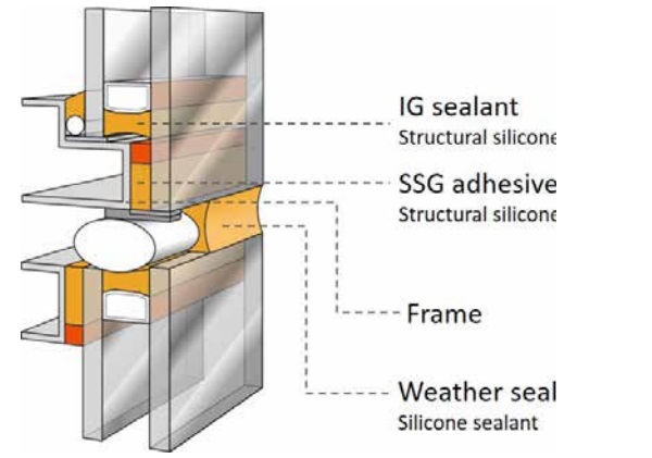
Their approvals and assessment are controlled in the European area by EOTA ETAG002 [3] and American area by ASTM C 1401 [4]. EOTA ETAG 002 [3] refers to exposure of the structural silicone joints to short-term wind loads (dynamic tensile stress), to cyclic thermal expansion between different components (dynamic shear stress) and to permanent dead load transfer (static shear stress). A similar concept is covered by ASTM C 1401 [4]. Stress from cold-bending of glass units and façade elements is not explicitly considered in [3] or [4] and thus requires careful and comprehensive engineering analysis.
![Figure 2: Tensile stress distribution in SSG-joints of cold-warped units according to Beer [2]: stress peaks at the corners based on non-linear FE analysis (left) and simplified uniform stress distribution (right).](/sites/default/files/inline-images/Fig2_62.jpg)
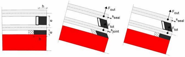
Significant reactions, which arise in the elastic silicone joints due to cold-bending, are:
• Permanent tensile loads – Stressing the SSG joint to bond the glass element to the frame (Ftot – Figure 4) as well as the IG joint of any insulating glass units which is cold-bent (Fout – Figure 4).
The permanent tensile stress is caused by restoring forces (back flipping) of displacement elastically applied on the flat produced glass unit and need to be properly withstood over the entire life cycle. Figure 2 shows the visualization of the distribution of the tensile stress caused by restoring forces of a coldwarped unit according to Beer [2]. High stress peaks at the element corners can be identified with precise simulation of the reaction forces in a non-linear finite element model based on hyper elastic bulk elements representing the elastic adhesive joints.
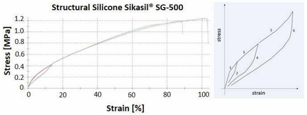
Consideration about Mullins effect could be called upon to evaluate such stress peaks in the joints: the mechanical response of the silicone adhesive and its stress-strain curve depends on the maximum loading previously experienced (Figure 3) and can be idealized as an instantaneous and irreversible softening of the stress strain curve that occurs whenever the load increases beyond its prior all-time maximum value.
Nonlinear elastic behaviour prevails when the load is lower than a prior maximum, while Mullins softening is a viscoelastic effect mainly driven by friction of fillers and sliding of polymer chains. Therefore, it can be argued that shortterm wind load superimposed to tensile load due to cold bending can produce a softening of the material and stress reductions.
Nevertheless, the extent to which stress peaks can be regarded as a temporary effect and can be compensated due to relaxation in favor of a uniform stress distribution requires further investigation or a material-dependent clarification.
Under the assumption of a uniform distribution as shown in Figure 2 on the right, the restoring force of a representative glass unit could also be calculated or experimentally determined using a dummy load, which could then be distributed as an idealized triangular load on the edges of the panel. Depending on the relevant needs, the resistance of the elastic adhesive joints against the permanent load can be adjusted by increasing the joint bite as necessary
• Permanent shear movements – affecting the SSG joint to bond the glass element to the frame (sjoint – Figure 4) as well as the IG joint of any insulating glass units which is cold-bent (sseal – Figure 4).
Under the influence of shear forces caused by geometric-related and reverse movement imposed to the bonded surfaces, possibilities to control the stress level in the joint without a significant increase in its thickness (clearance of bonded surfaces) are limited. However, while the restoring forces acting out-of-plane of the cold-bent and cold-warped unit can only be reduced by decreasing the glass stiffness (glass thickness, glass size, elastic / viscous and thermo-elastic interlayers) or by using mechanical restraints, there are possibilities for actively influencing the reduction of shear movements in the elastic adhesive joints by evaluating different cold-bending procedures:
- A very effective option to remove the permanent shear stress in the SSG joints due to cold bending is using hot-bent frame members, so that only the glazing is coldbent. The glass unit can be cold-bent on the pre-shaped frame and temporarily fix to it by mechanical devices; application of the SSG-joints can follow. After the adhesive is completely cured, mechanical devices can be removed. The introduction of significant shear movements in the SSG joints (sjoint – Figure 4) is permanently prevented.
- An other option to limit the permanent shear stress in the SSG joints due to cold bending is to temporary fix by mechanical devices the glass unit to the frame and cold bent them; after that, application of the SSG joint can follow. When adhesive is completely cured, the mechanical temporary devices can be removed. Permanent tensile stress will arise in the SSG joints; shear stress will arise in the SSG joints too, but its duration will be limited to the timeframe from production to installation, when cold-bent shape will be restored.
If one considers that the level of shear movements does not only depend on the displacement needed to set the curvature but also on the geometry of the bonded components, it is obvious that the system design itself could have important influence on limiting permanent forces in the adhesive joints without further increasing the effort and complexity of factory production and bonding of façade elements.
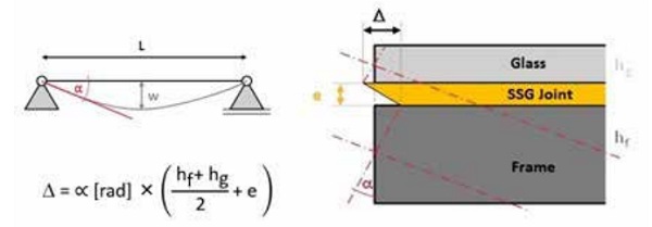
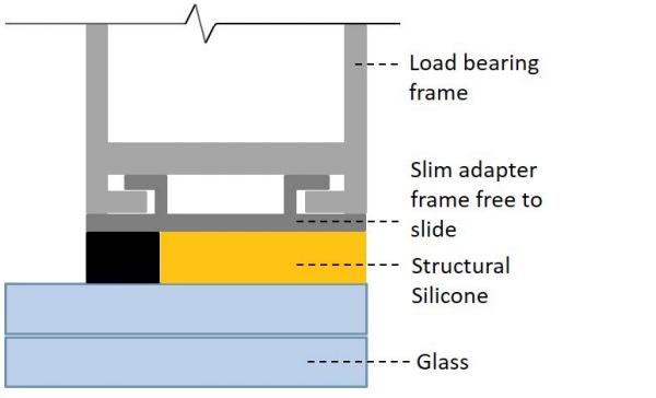
As shown in Figure 5, the degree of shear deformation is significantly influenced by the cross-sectional height of the bonded components and does not just depend on the displacement and the curvature of the coldbent element. That means, the larger the cross-sectional height of frame and glass, the bigger the offset of the bending axis and surfaces of the bonded components and the bigger the reverse movement ∆ of the bonding surfaces, whereas the accommodation of large shear movements within the allowable stress can only be realized by a massive increase of the adhesive joint thickness. In other words: permanent shear stress in the SSG joints can be significantly reduced by increasing the thickness of the structural silicone joint but also by a massive reduction of the crosssectional height of the bonded components. This can be achieved e.g. by:
• Using flat slim frames mechanically connected to a load bearing frame in such a way that free in-plane relative displacements are allowed (Figure 6). The flat slim adapter frame can be bonded to the glass unit at the factory site; after joints are completely cured, application of required out-of-plane displacements for cold bending can occur on site.
• Using flat slim adapter frames which are bonded to the flat glass units at the factory site. After joints are completely cured, the bonded assembly can be cold-bent and fixed to a pre-shaped load bearing frame on site.
4. Permanent Effects on SSG Joints due to Cold Bending
After determining the permanent load reactions, which are created in the elastic adhesive joints by cold-bending or coldwarping of SSG units, the influence on the load-capacity and durability of the structural silicone bonding needs to be evaluated. ASTM C 1401 [4] requires a strong limitation of permanent load effects, such as deadload shear, to maximum 1psi (0.007MPa), while European EOTA ETAG 002 [3] only gives partial guidance on how to proceed.
The definition of a creep test under long-term shear in superposition with cyclic tensile loading in Section 5.1.4.6.8 of [3] helps to get an indication about the long-term performance of the structural silicone. It defines the influence of permanent shear stress on dead-load unsupported systems, what means that the total weight of the glass is permanently transfrered by the structural silicone only.
In addition to the creep test, which requires massive restriction on residual shear deformation after complete unloading besides an adequate material resistance under permanent loading, a creep factor of at least 10 is defined by [3] in the same section. The allowable shear stress has to be reduced by the creep factor in addition to the dynamic safety factor when the elastic adhesive joints are required to take the total dead load.
The procedure defined in [3] can be applied to the evaluation of elastic adhesive joints which are used in cold-bent SSG units only to a certain extent. Indeed, while creeping test defined by [3] analyzes the combined effect of permanent shear load and temporary or dynamic tensile load, the effects of coldbending produces permanent tensile loads and limited-in-distance shear movement. Considering this, one could take over the approach of [3] and reduce the allowable stress for dynamic tensile loading by an additional creep factor γc ≥ 10, with respect to the permanent action of the restoring forces and in order to permanently restrain the cold-bent and structurally bonded glass units.
For evaluating permanent shear movement [3] has no practical approach since the use of the allowable static shear stress for this case would hardly lead to applicable joint thickness, in most cases. Moreover, it must be considered that the imposed displacement is indeed permanent but limited in magnitude, as related to a one-time setup and does not increase over the life cycle. Thus the risk of creep is structurally non-existent. Instead, a process must be found which eventually defines a maximum permissible level for the relaxation of permanently distorted joints. In this context, it should be mentioned that an allowable relaxation of the adhesive joint in shear direction must not have effects in a reduction of material resistance.
For this purpose, following tests have been performed on structural silicone adhesives:
• Lap-shear tests with structural silicone joints loaded up to failure as per following conditions:
- Lap-shear samples tested up to failure at 23°C / 50% relative humidity with no preliminary loading and used as reference
- Lap-shear samples tested up to failure at 55° C / 95% relative humidity with no preliminary loading
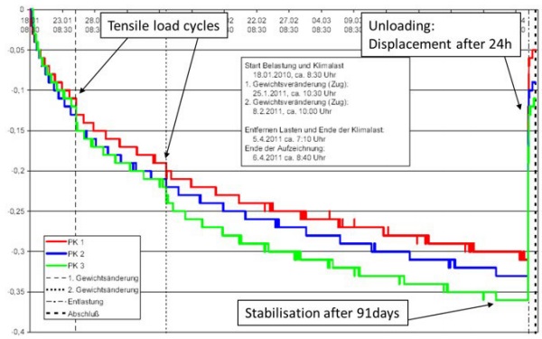
- Lap-shear samples loaded for 91days under different levels of imposed shear movements and tested up to failure at 55° C / 95% relative humidity.
Comparison of results obtained from the above lap-shear samples shows that the ultimate strength of the joint does not decrease, if adhesive has previously experienced an imposed deformation up to maximum 30% design load set by [3].
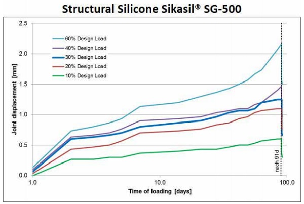
• Creep tests according to EOTA ETAG002 [3], associated to permanent loading from 10% to 60% the design load defined by [3]. The test shows that up to maximum 30% the design load set by [3], joint movements are stabilized and do not increase further after 91 days, although residual deformation are recorded (Figure 8).
Based on above considerations and test series, extended design values could be proposed to include shear strength accounting for relaxation effects to use when shear movements are imposed to joints, but no permanent shear loads to be transferred. For an entire evaluation of the structural silicone joints, the influences of wind, live loads and climatic effects must be taken into account too. Short-term and permanent load combinations should be defined and combination of utilization levels out of existing stress and allowable stress should be evaluated with regard to relevant load directions and durations.
Conclusions
A variety of criteria exists for optimizing the bending process of curved glass elements in façade applications, which take into account different design and manufacturing process and needs. Besides the preferably discussed visual, technical and cost-driven aspects, influences on the joint design of SSG units must also be considered. How the negative influence of large shear deformation can be significantly reduced on permanently loaded structural silicone joints through a clever system design and use of leaner adapter frame is shown in Section 3.
Furthermore, the relationship between EOTA ETAG 002 [3] and the stress of elastic adhesive joints in cold-bent units is established in Section 4. The observation shows that the existing approvals of structural silicone adhesives on the basis of [3] and [4] cannot or can only be consulted to a limited extent for the verification of cold-bent SSG units. More extensive guidelines are needed for evaluation and calculation methods of cold-bent elements, as well as definition of meaningful allowable stress.
References
[1] Dodd, G.; Thieme, S.: Comparison of curved glass and cold bent panels. GPD Glass Performance Days 2007, S. 83-86.
[2] Beer, B.: Structural Silicone Sealed Cold-Bent Glass – High-Rise Projects Experience Leading to a New Design Concept. GPD Glass Performance Days 2015, S. 235-240.
[3] EOTA ETAG 002-1, Structural Sealant Glazing Systems Part 1: Supported and Unsupported Systems, 1998.
[4] ASTM C1401, Standard Guide for Structural Sealant Glazing, 2014.