Source:
Challenging Glass 7
Conference on Architectural and Structural Applications of Glass
Belis, Bos & Louter (Eds.), Ghent University, September 2020.
Copyright © with the authors. All rights reserved.
ISBN 978-94-6366-296-3, https://doi.org/10.7480/cgc.7.4428
Authors:
Martin Jensen Meyland a, b
Jens Henrik Nielsen a
a Technical University of Denmark, Department of Civil Engineering, Denmark
b Ramboll Denmark A/S, Private & Public Buildings East, Structures & Façade Engineering, Denmark

The failure of glass has been studied extensively by many researchers. However, the focus has previously been on the static to quasi-static, rate-independent behaviour. It is commonly accepted that the strength of glass is sensitive to the applied loading time, however, the amount of research in the field of loading rate dependency seems very limited.Consequently, the effect of loading rates on the strength is sparingly described in the available literature despite its relevance when designing for impact and blast loads. The present paper presents an ongoing research project considering the failure of glass at high strain-rates.
It provides a brief review of existing studies showing a strength increase with loading rates relevant for e.g.blast loads. Based on existing experimental work, a numerical model considering different failure models is presented. The different considered failure models are then compared and discussed for their applicability. The paper also includes an outlook of the project, briefly explaining a novel concept for a high strain-rate test setup planned to be built during the summer of 2020.
1. Introduction
Predicting the fracture behaviour of glass at high strain-rates has become a sought for discipline within the design of building facades in today’s societies where terrorism is gaining an increased focus.Glass is seen as a very popular construction material that often is covering large areas of architectural facades, having the function to deliver daylight and views to the occupants while protecting them from outside conditions.
However, in the event of a nearby blast, the glass will, due to its brittle nature, shatter into small fragments that are accelerated to velocities possessing a serious threat. Typically, these fast-moving fragments are the cause of many injuries (Norville et al. 1999; Rudick and Norville 2000; Smith 2001). Being able to design glass facades that mitigate the effect of an explosion is crucial.
Much effort has already been put into the research of laminated glass, which often is used in structures for protection against blast (Hooper et al. 2012; Larcher et al. 2012; Zhang et al. 2013a; Kuntsche 2015; Pelfrene 2016; Del Linz et al. 2017; Osnes et al. 2019). However, the focus has been on the laminate and the global responses while the glass characteristics themselves were of less interest. Not only is the dynamic glass strength of great importance for the prediction of failure and the performance of risk assessments but also for the design of bear in sub-structures in a façade, as the amount of blast energy that can be absorbed by the glass until failure is an important quantity.
As a contribution to the identified lack of knowledge, this paper presents the work of an ongoing research project considering the failure of glass at high strain-rates. First a brief review of existing studies is provided followed by a closer look on the project’s two main parts: (i) the numerical modelling of glass fracture, and (ii) an outlook on future experimental work where small soda-lime-silica glass specimens are investigated at high strain-rates.
2. Failure characteristics of glass
When dimensioning glass structures, the material strength must be considered as a key parameter. In simulations of glass fracture, it is an important parameter for capturing crack formations and the fragmentation as realistically as possible. However, pointing out a unique value is difficult due to the large variations observed experimentally. Several aspects are contributing to the strength definition, which in particular are the surface quality, the size of the glass element, the loading (time and intensity), and the environmental conditions. As the material is brittle and therefore incapable of redistributing stresses, it is very sensitive to surface flaws and other defects as those result in stress concentrations. Like other brittle materials, a glass element will suddenly fail without noticeable warnings when the stress intensity at a crack tip loaded in tension reaches its critical value.
In the quasi-static load regime, where the strength of glass is known to be insensitive to moderate loading rates, the strength prediction is well-described by the theory of linear elastic fracture mechanics (LEFM). For brittle materials, it is common only to consider the Mode I crack opening(tensile opening). The arising elastic stress intensity around a crack tip can then be represented by a stress intensity factor KI, which first was introduced by Irwin (1957). Once the stress intensity factor reaches a critical value, denoted as the fracture toughness KIc, a crack starts growing until failure. In a humid surrounding environment, however, a crack may also start growing slowly below that critical value when exposed to a positive crack opening stress. This is known as sub-critical crack growth and is the reason why the strength of loaded glass decreases over time(Wiederhorn 1967; Wiederhorn and Bolz 1970).
The opposite is observed when the glass is loaded very rapidly, for instance, in blast and impact scenarios. Under such conditions, the material demonstrates a strong strain-rate dependency where the strength increases with the loading rate. A consistent definition of the strength development is now here to be found most likely because of the complex nature of determining dynamic material characteristics. However, a small number of experimental studies exist on investigating the dynamic glass strength. Peroni et al. (2011) and Zhang et al. (2012) performed compression and split tensile tests on monolithic soda-lime-silica glass (SLSG) specimens in a split Hopkinson pressure bar (SHPB) setup at strain-rates up to 103s-1.
The same testing technique was used to study strain-rate effects on the flexural strength of borosilicate glass (BSG) in four-point bending and equibiaxial bending considering different surface conditions (Nie et al. 2009; Nie et al. 2010). Most recently, a servo-hydraulic high-speed test rig was used by Meyland et al. (2019a) to test the flexural strength of small circular soda-lime-silica glass specimens with two different surface conditions in a ring-on-ring configuration. Despite the differences in the applied testing methods, all studies confirm a strength increase with loading rate, which by some of the mentioned authors is explained by the fact that the effect of sub-critical crack growth has been reduced or even eliminated at the observed loading rates.
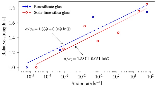
Considering blast-related engineering problems where lateral loads are acting on thin glass panes, the load case is of a more global character that introduces bending (tensile) stresses to the material. The flexural strength at high strain-rates is, however, sparingly described in the available literature and so far only covered by Nie et al. (2010) and Meyland et al. (2019a). The results from both studies are compared in Fig. 1 for comparable surface conditions. With an assumed linear logarithmic regression, it is evident that both glass types exhibit a similar trend in strength development as a slope of 0.049 is found for borosilicate glass and 0.051 for soda-lime-silica glass.
3. Numerical failure formulations for brittle materials
The finite element method (FEM) is a versatile tool for many engineering applications. For simulation of dynamic events such as blast waves from explosions or impact scenarios, the explicit FEM analysis is widely used. An extensive effort has been put into the research of the numerical simulation of crack initiation and formation in solid materials. Different approaches do exist such as the cohesive zone element (Camacho and Ortiz 1996), the extended finite element method (XFEM) (Moës et al. 1999), the meshless method (Belytschko et al. 1995) or the particle conversion method (Johnson et al. 2002).
However, many challenges are still to deal with such as the dynamic failure of thin-walled structures. Especially a certain effort needs to be directed towards the simulation of windows commonly covering large surfaces. Those will consequently require a massive amount of elements to capture the crack formation, which is a disadvantage with respect to computational time and therefore a limiting factor for the practically use.
In the following, the focus will be given to a more crude approach to crack simulation, namely the element deletion technique, which is practically applicable for the simulation of glass under low-velocity impact and blast. It comes with the great benefit that it is relatively simple to implement, and any failure criterion or damage formulation can be coupled with it. However, it is inherently mesh dependent, as a crack only can extend by deleting an element. Also, the element deletion is not an optimal solution to apply for structural applications where it is expected that created cracks close again. In most engineering problems, a more coarse mesh is used, which makes it difficult to predict the correct state at a crack tip leading to an overestimation of the fracture energy (Unosson et al. 2006). Thus, the use and interpretation of fracture models using the element deletion technique should be done with caution.
Hereinafter, three different fracture models using the element deletion technique will be presented, where the first two are readily available in most commercial FEM codes,and the last one is implemented by as a user subroutine in ABAQUS/Explicit.
3.1. Johnson-Holmquist (JH-2) ceramic model
In the early 1990s, Johnson and Holmquist (Johnson and Holmquist 1994; Holmquist et al. 1995) proposed an improved constitutive model (JH-2) for ceramics and other brittle materials intended for simulation of the mechanical response and failure at large strains, high strain-rates, and high pressures. Initially, it was developed for brittle materials under impact conditions, e.g. ballistic impact. However, the model also has become quite popular among researchers for simulation of lateral loads on thin glass panes as used in windows (Zhang et al. 2013; Zhang et al. 2015; Zhou et al. 2019).
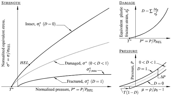
The JH-2 model is available in ABAQUS/Explicit as a pre-defined user subroutine and is composed of three sub-models, as schematically shown in Fig. 2, which describes the deviatoric strength of the material, the damage evolution, and the pressure-density relationship. Starting with the material strength, σ*, it is expressed in terms of a normalized von Mises equivalent stress taking into account strain-rate effects and material damage as well as an intact and fractured strength:

where σi* is the normalized intact strength, σf* is the normalized fractured strength, and D is a damage variable ranging from 0 (intact) to 1 (complete fracture). All the normalized equivalent stresses have the general form σ*=σ/σHEL, where σ is the actual von Mises equivalent stress and σHEL is the equivalent stress at the Hugoniot elastic limit (HEL), at which a one-dimensional (uniaxial strain) shock wave exceeds the elastic limit of the material. Strain-rate effects are directly considered in the formulation of the intact and fractured material strength that is given by:
![]()
and

with A, B, C, M and N being material-specific model parameters, and P∗ defining the normalized pressure as P*=P/PHEL, where P is the actual pressure and PHEL is the pressure at the HEL. The tensile capacity of the material is limited by the normalized maximum tensile hydrostatic pressure T*=T/PHEL with T denoting the maximum tensile hydrostatic pressure, the material can withstand. A dimensionless strain-rate is used as ε̇*=ε̇/ε̇0, where ε̇ is the actual strain-rate and ε̇0=1.0 s-1 is the reference strain-rate.
The damage variable accumulates with plastic strain according to:

where Δεp is the plastic strain during a cycle of integration, and εpf is the plastic strain at complete fracture under constant pressure, P, given as:

where D1 and D2 are material-specific constants and P* and T* are as defined previously in Eq. (2). It follows from Eq. (5) that the material is not able to undergo any plastic strain at P*=−T*; but εpf increases as P* increases.
The pressure-density relationship for the material in compression is expressed as:
![]()
where K1, K2 and K3 are material constants with K1 as the initial bulk modulus; and μ=ρ/ρ0−1 in which ρis the current density and ρ0 is the initial density. When damage begins to accumulate, the effect of dilation can occur, which is included by the additional incremental pressure, ΔP. This pressure increment is determined from energy consideration. As the strength decreases when the material undergoes damage, it produces a decrease in the deviatoric elastic strain, denoted as ΔU. The elastic energy loss is converted into potential hydrostatic energy by incrementally increasing ΔP according to:

where β defines the fraction (0≤β≤1) of the elastic energy loss that is converted into potential hydrostatic energy (for more details, the reader is referred to the references). In the case of tension (μ<0), Eq. (6) is replaced by P=K1μ.
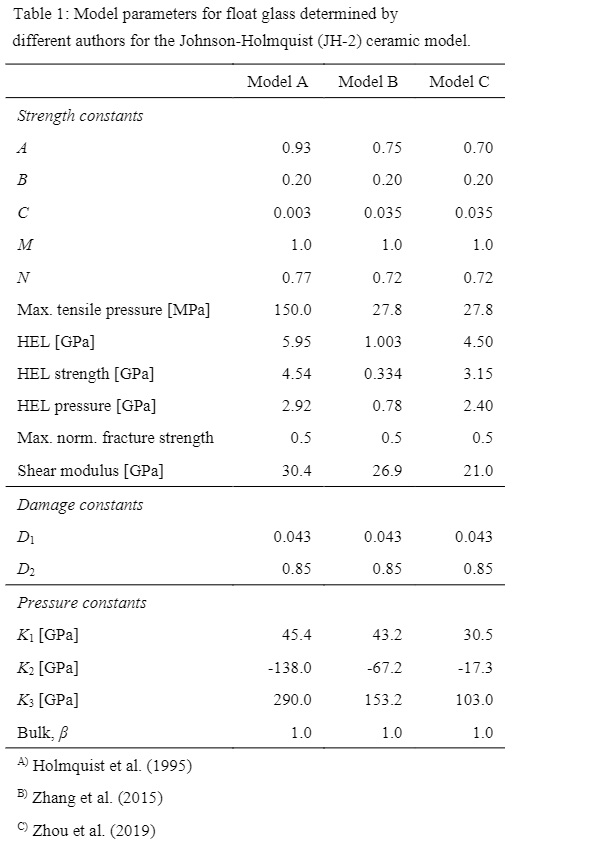
Model parameters for modelling the mechanical behaviour of float glass at high strain-rates were firstly determined by Holmquist et al. (1995) based on uniaxial compression and tensile tests at two different strain-rates (10-3s-1 and 250 s-1) as well as plate impact experiments. The determined parameters are summarised in Table 1 under Model A. Zhang et al. (2015) modified the original JH-2 model parameters, as they considered that the strength of the glass specimens used by Holmquist et al. (1995) was higher than that of common float glass used in today’s architectural glazing. Therefore, they conducted a new series of compression and tensile tests that also were covering higher strain-ratesin the range between 619 s-1 and 1465 s-1.
However, no plate impact experiments were conducted to obtain the HEL. Instead, they introduced a pseudo-HEL, which is taken as the maximum uniaxial strength and the associated pressure value from the split Hopkinson pressure bar tests. Their proposed model parameters are given in Table 1as well, hereinafter referred to as Model B.A newly published article (Zhou et al. 2019) discussing the application of the JH-2 model for the damage assessment of float glass under blast loading, proposes a further set of model parameters where the parameters from Zhang et al. (2015) are combined with the findings from Holmquist et al. (1995) and other available test results. The obtained parameters are summarised in Table 1 under Model C.
3.2. Smeared crack model
A less comprehensive approach for fracture simulation of brittle materials in the finite element method is the smeared crack model introduced by Hillerborg et al. (1976) for concrete, which uses the cohesive zone concept. The term smeared crack denotes that the model does not represent a micro-crack explicitly, but accounts for the effect of a crack by an elastic stiffness reduction, or even elimination, at the integration points of an element. A bilinear traction-separation law, as illustrated in Fig. 3, characterises the stresses over the crack for the cohesive zone model that is used for the built-in material model *Brittle Cracking in ABAQUS/Explicit.
The model is coupled with a linear-elastic material behaviour prior to damage with an initial stiffness K=E/Le, where E is Young’s modulus of the material and Le is the undeformed distance between the nodes. Once the maximum principal stress at an integration point reaches the fracture strength, σ0, the damage is initiated. This is also known as the Mode I, Rankine crack initiation criterion. At the point of crack initiation, the tensile stress perpendicular to the crack decreases with increasing crack width until the work performed on the element matches the fracture energy, GfI.
As soon as full fracture is obtained, i.e. at a crack opening width of δcf, the element can no longer carry any tension loads in that direction. The element can still withstand compression loads when the crack closes. However, the model is to be applied with caution, as it removes elements that are fully fractured from the model and, therefore may not represent the correct structural behaviour in the case where cracks close again. For a pure Mode I failure, it may be reasonable to use the brittle cracking failure criterion to remove elements, as a crack only is loaded in tension.
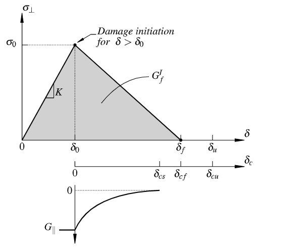
Whereas the crack initiation is based on Mode I fracture only; the post-cracked behaviour includes Mode II as well as Mode I. During damage accumulation, the shear modulus, G∥, is reduced in function of the crack opening width. At a crack opening displacement δcs, G∥ is reduced to zero. Moreover, a relative nodal displacement δu at ultimate failure of the element is to be defined, at which the element is removed from the simulation. This may either beat the point where the stiffness across the Mode I crack is reduced to zero, i.e. δf, or after in order to delay the element removal. When a crack initiates, the elastic strain energy accumulated in the element up to that point is constituting part of the total fracture energy. Hence, the fracture energy equals the area under the triangular curve in Fig. 3, which can be expressed as:

For consistent fracture energy to be obtained, the displacement at tensile failure should not be smaller than the displacement at crack initiation, i.e. δf≥δ0. Applying this inequality to Eq. (8) then gives:
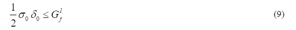
and with δ0= Leσ0/E, there exists a critical element size, Le,cr, for which the fracture energy still can be represented correctly:
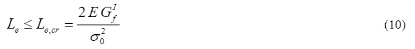
With Young’s modulus of E = 70 GPa, a fracture energy GfI≈ 8.0J/m2 (in accordance with Griffith theory (Griffith 1921)) and assumed fracture strength of 100 MPa, the critical element size would be around Le,cr≈0.1 mm for glass, which is a quite severe limit, and not a practically applicable meshing size for engineering problems regarding the computational time. A more detailed analysis of the effect on the fracture energy when the element size criterion is not satisfied is provided by Pelfrene et al. (2016a), concluding that the fracture energy in the simulations may be overestimated compared to the physical material value. In case, the criterion cannot be met, i.e. when Le,max>Le,cr, the relative nodal displacement at which the element stiffness is reduced to zero can be calculated as:
As the smeared crack model initially was developed for concrete and other brittle/quasi-brittle materials in the quasi-static load regime, where the rate of loading is assumed not to affect the mechanical material properties, one has to assign different strength properties in a blast simulation depending on the considered loading rate. However, in most blast-related engineering problems, the loading rate may vary and a model that can account for such variations isto prefer. Nevertheless, this paper still includes this model in further discussions exactly because of its simplicity and the widely seen practically application.
3.3. Immediate element failure model with a strain-rate dependent strength evaluation
A more straight forward approach to the failure simulation of glass with strain-rate effects included is aimed at, as the smeared crack model is considered being too elementary for the application inblast-related problems, and the more comprehensive JH-2 model requires a wide range of quasi-static to dynamic experimental data for the determination of the numerous model parameters, which not always are sufficiently available. Moreover, the latter has its great strength in simulating projectiles impacting solid ceramic blocks for the determination of for instance the penetration depth.
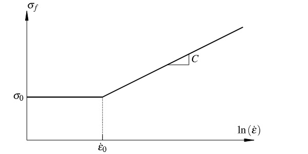
As a first step towards the development of a more simple strain-rate dependent failure model, the element deletion technique is used as in the *Brittle Cracking model, but with the distinction that an element is immediately removed from the simulation upon reaching a rate-dependent fracture strength, σf. This means that the stresses in the element are set to zero within a single time increment when reaching the failure stress at one or more integration points, i.e. no damage softening phase is present. Assuming a linear logarithmic strength growth, as indicated in Fig. 1, after a certain strain-rate threshold, the fracture strength can be formulated as:
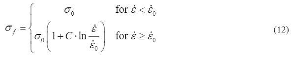
where σ0 is the quasi-static (reference) fracture strength, C is a strain-rate constant defining the slope of the strength increase, ε̇ is the actual strain-rate, and ε̇0 is the quasi-static (reference) strain-rate. The strength model given in Eq. (12) is illustrated in Fig. 4, where a constant material strength is assumed for ε̇<ε̇0.
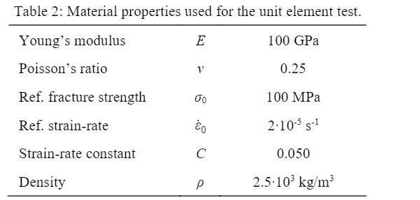
Such a failure model is not readily available in ABAQUS/Explicit. However, the software comes with the option that allows the definition of new material models through a VUMAT user subroutine. The implementation assumes a linear-elastic material behaviour prior to element failure. The element failure is then based on the Rankine principal stress criterion, which is a commonly applied failure criterion for brittle materials on a macroscale. The uniaxial behaviour of the implemented failure model is tested on a single unit element (1×1×1mm) with assigned material properties, as listed in Table 2.
Uniaxial tension is applied to an eight-node brick element (reduced integration) with a ramped displacement of 2 μm over 0.1 s, 0.01 s and 0.001 s, respectively, resulting in three different strain-rates and consequently also in three different fracture strengths according to Eq. (12). It is evident from Fig. 5, showing the stress as a function of displacement, that the fracture strength as intended increases with strain-rate. Once the fracture strength is reached, the element can no longer carry any loads as the material stiffness is set to zero immediately.
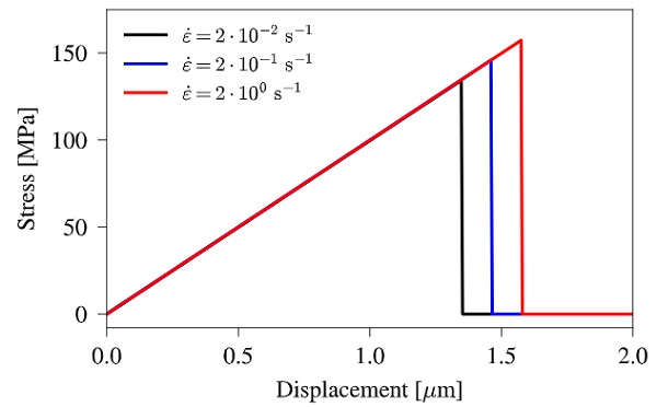
Moreover, no oscillations are seen after the stiffness removal. However, in case the failing element is surrounded by elements that have not reached the failure criterion, the situation may be different. It is reported by Pelfrene et al. (2016a) that surrounding elements will experience heavy oscillations at a sudden release. In larger simulations, those stress wave reflection may cause the unexpected failure of elements away from the original crack propagation (Song et al. 2008).
4. Dynamic ring-on-ring test on monolithic glass
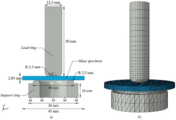
Dynamic ring-on-ring tests on monolithic float glass conducted by Meyland et al. (2019a) are used for comparison of numerical simulations exploring the material models introduced in Section 3. The in-house made test setup, designed in accordance with the international standard ASTM C1499-15 (2015), consists of a small load ring having a contact diameter of 7.5 mm and a larger support ring with a contact diameter of 25 mm, both made of hardened steel with a tip radius of 2.5 mm. A servo-hydraulic high-speed test rig with a load capacity of 50 kN and achievable piston velocities up to 5 m/s was used for the tests, with the load ring mounted to the movable piston and the support ring to the lower cross-head.
The considered tests were performed on circular, monolithic soda-lime-silica glass specimens with a diameter of 45 mm and an averaged measured thickness of 2.85 mm at seven different strain-rates ranging from 2.2∙10-5s-1 to 6.2∙101s-1 (equalling the target piston velocities ranging from 1.7∙10-3mm/s to 3000 mm/s). The hereinafter presented simulations are for simplicity only looking at two different loading rates that are corresponding to the target piston velocities 10 mm/s and 1000 mm/s, in order to include rate effects in the verification. The corresponding experiments used for comparison are comprised of 28 and 16 valid tests, respectively.
Simulations of the experiments are performed in the commercial finite element software ABAQUS/Explicit. Only the main parts of the test setup are represented in the numerical model: (i) part of the load ring extension, (ii) the glass specimen, and (iii) part of the support ring. They are shown in Fig. 6 with the associated dimensions and the applied mesh. The assigned linear-elastic material properties are given in Table 3. Six-node wedge elements (C3D6) are used to model the load ring extension, where as the rest of the model is meshed by four-node tetrahedral elements (C3D8). Especially for the glass part, it is found by Pelfrene et al. (2013) that tetrahedral elements are performing better regarding the modelling of fragmentation. Moreover, a fine and unstructured mesh with uniform element sizes in the magnitude of 0.5 mm, resulting in 243,930 elements, is applied to the glass specimen as this may favour the creation of a more realistic fracture pattern (Song et al. 2008; Pelfrene et al. 2016b).
The bottom side of the part constituting the support ring is fixed for movements in all three directions, while the top of the load ring extension is fixed for movements in the horizontal plane and allowed to move vertically in the y-direction with a pre-set velocity. This is a similar loading condition as the one used in the experiments where a velocity was assigned to the piston in a displacement-controlled loading setting. The glass specimen is held in place between the rings by friction forces with a prescribed friction coefficient of 0.1. The contact between the glass specimen and the steel rings is established with general contact properties as defined in ABAQUS/Explicit.
The failure evaluation of the glass specimen in the numerical model is based on forces measured on the load and support ring side. Both sides are considered in order to see to what extent a dynamic load equilibrium is achieved. The force on the load ring side is determined from strains taken on the surface of the load ring extension at a distance of 10 mm measured from the top. Simpler is the calculation of the force on the support ring side, which is taken as the sum of all vertical reaction forces.
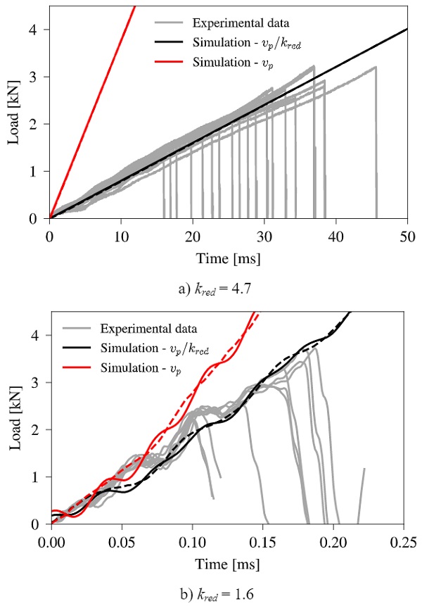
The actual piston velocity is unknown from the experiments, as the deformation of the glass specimens over time was not recorded. Hence, the velocity applied in the simulations is the target piston velocity, vp, which might be an overestimation due to e.g. energy losses at impact, as demonstrated through a pure linear-elastic simulation without the use of any failure model. Consequently, a velocity reduction factor, kred, is introduced to align the simulations with the conducted experiments. For both considered target piston velocities a reduction factor of 4.7 and 1.6 is determined, respectively. The effect of kred is shown in Fig. 7, where simulations with and without a reduced target piston velocity are plotted together with the experiments.
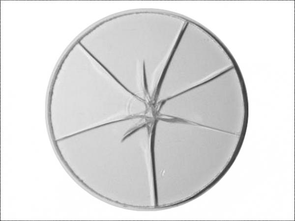
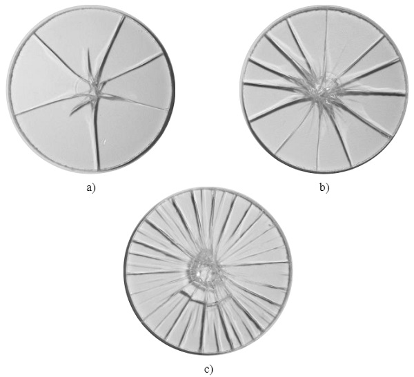
Not only is the loading path and the failure load of interest in the validation of the numerical fracture models but also their ability to form realistic failure patterns (to some extent). As it was impossible to keep the fractured glass specimens in one piece after testing at the high loading rates, the images of the fracture patterns provided in Fig. 8 are from representative specimens tested at the lowest target piston velocity of 1.7∙10-3mm/s. It is evident that the number of fragments increases with fracture strengths, which is caused by the increasing strain energy stored in the glass (Haldimann et al. 2008). In terms of strain-rate, this also means that a lower strain-rate should lead to fewer fragments compared to a higher one at which the strength is assumed to have increased.
The fracture strength must be considered as one of the most decisive parameters for the crack formation in the numerical simulations. However, different approaches in defining the strength are used by the three fracture models discussed in the previous section. A strain-rate dependent strength model is applied to the JH-2 ceramic model and the immediate element failure model, where as a specific strength value isto be pointed out for the smeared crack model. The latter two uses strength values provided by Meyland et al. (2019a).
4.1. JH-2 ceramic model
Three different JH-2 ceramic models are applied to the glass elements with model parameters as given in Table 1 and compared. The loading curves for both considered piston velocities are shown in Fig. 9 in comparison with the corresponding experimental results, where only the loading path up to fracture is shown. It is evident that the model's capability of simulating these experiments is not prominent. At the lower velocity, the initiation point of fracture in Model A is at a comparable level to the experiments but is followed by a phase of plastic yielding before complete failure occurs, which is not a physical representation of glass failure.
In Model B and C, a low value for the hydrostatic tensile pressure is initiating a too early failure. All three models overestimate the fracture strength significantly at the higher piston velocity and do not represent the experimental observations at all. The tremendous strength increase can be explained by the strength model, which is a function of the pressure applied to the material. As the specimen comes with a high bending stiffness, most of the elements experience a high pressure at the time of impact by the load ring before bending initiates, resulting in higher material strengths.
Table 4 gives an overview of the simulated fragmentation of the glass specimen. With parameters given for Model A and C, a realistically looking failure pattern can be obtained even for the high piston velocity where the size of fragments is decreased, as a consequence of an increased fracture strength. No bending induced failure is activated for Model B as only the elements local around the impact area of the load ring are failing.
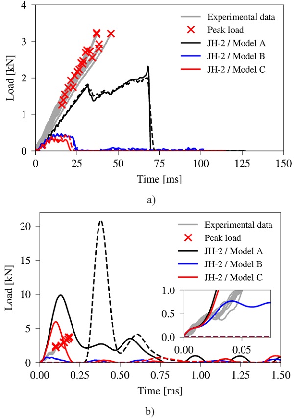
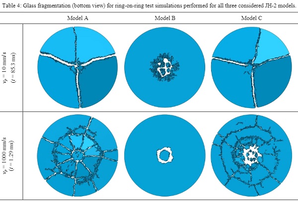
The above investigations indicates that the JH-2 ceramic model is unsuitable for the simulation of bending induced failure of glass at various strain-rates in regard of fracture initiation and the post-fracture behaviour even though it is capable of simulating realistically looking fracture patterns by choice of proper model parameters. This most likely can be explained by the fact that the model initially was developed for the simulation of brittle materials within ballistic applications where a local area is considered for the impact of a projectile. Due to the very local phenomenon, the bending is neglected and only the penetration into the solid material is accounted for, which also is evident from the types of experiments conducted for the determination of the model parameters.
4.2. *Brittle Cracking
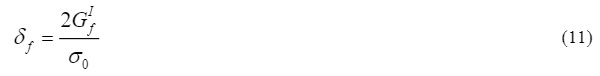
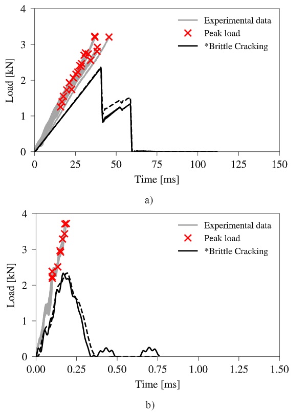
For *Brittle Cracking in ABAQUS, some extra parameters need to be defined in addition to those given in Table 3. From Meyland et al. (2019a) the dynamic fracture strengths are taken as σ0,a= 229 MPa and σ0,b= 297 MPa for the two considered target piston velocities, respectively. The fracture energy for soda-lime-silica glass is set to GIc=8.0J/m2in accordance with the value stated in Section 3.2. Based on that, the element length criterion is not met for any element in the applied mesh. Hence, the crack opening displacement for tensile failure, δcf, is determined from Eq. (11). The displacement for shear failure, δcs, and ultimate failure, δcu, is chosen to equal the tensile failure displacement, i.e. δcs= δcu= δcf.
Fig. 10 shows the simulated loading curves for both tested loading rates together with the corresponding experimental results. A more natural post-failure behaviour is obtained due to the steep strength reduction seen after crack initiation. However, at the lower loading rate, the load is not dropping down to zero after reaching the fracture strength. At that point, the first cracks are initiated on the bottom side of the specimen without being fully extended through the thickness, resulting in a stiffness reduction until complete failure occurs.
Similar behaviour cannot be observed for the higher loading rate, which presumably can be explained by the more rapid loading that forces the cracks to open until full failure is achieved. Both simulated loading rates initiate failure at loads comparable to the experiments. This is not surprising due to the assigned fracture strengths that are taken from the corresponding experiments as the fracture model does not account for strain-rate dependencies directly.
Looking further on the glass fragmentation given in Fig. 11, the same number of fragments is counted for both loading rates with a realistically looking failure pattern. As similar fracture strengths are obtained, even though different strengths were assigned to the simulations, this is an expected outcome because of comparable strain energies reached in the specimen at failure. An explanation for the missing strength increase is found in the model of the test setup (see Fig. 6), where severe oscillations were observed in the strain signals taken on the surface of the load ring extension as well as in the reaction forces taken at the support ring side. This consequently required a Butter worth filter to filter out the high frequency domains to be able to interpret the results. By doing so, the actual fracture strength may also have been filtered out.
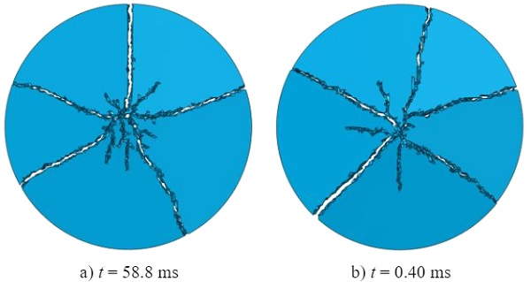
Usually, one would expect a larger number of fragments at a higher loading rate as the fracture strength is assumed to increase. However, this behaviour could not be captured in the simulations. Nevertheless, the smeared crack model is considered not being a suitable solution for the simulation of blast-related engineering problems due to the missing strain-rate dependency.
4.3. Immediate element failure model (VUMAT user subroutine)
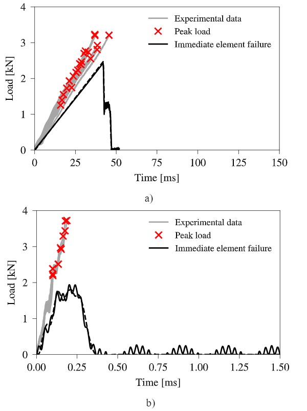
The cracking in the immediate element failure model is in addition to the parameters given in Table 3 governed by a reference (quasi-static) fracture strength, σ0, a reference (quasi-static) strain-rate, ε0, and a strain-rate constant, C, that controls the strength growth. With reference to Meyland et al. (2019a), the strength value obtained at the lowest tested loading rate is taken as a reference with the value 169 MPa together with the corresponding strain-rate 2.2∙10-5s-1. The strain-rate constant is defined by the slope shown in Fig. 1 for soda-lime-silica glass with the value 0.051.
The loading curves obtained from the simulations with the immediate element failure model are provided in Fig. 12 for both loading rates. Great similarity is seen between this model and the built-in smeared crack model regarding crack initiation and post-failure behaviour. However, full fragmentation is achieved faster at the lower loading rate due to a shorter time with reduced stiffness after the first crack initiation, where as identical loading times are seen for the higher loading rate.
Due to the implemented strength growth defined by the b strain-rate constant, one would expect a strength increase when increasing the loading rate. This behaviour is not evident from the ring-on-ring test simulations. Therefore, some extra simulations were made at seven different loading rates that are corresponding to piston velocities ranging in-between 10 mm/s and 1000 mm/s. The applied velocity reduction factor, kred, as previously introduced in this section, is assumed to vary linearly between those two target piston velocities.
The supposed reason why a larger reduction factor is required for the low target piston velocities compared to the high ones is that a slower-moving piston is impacting the glass specimen with lower inertial forces. This means that the high bending stiffness of the specimen will affect the movement of the piston significantly, reducing the velocity. When the piston moves faster the opposite happens because of higher inertial forces at which the bending stiffness of the specimen then becomes less significant relatively.
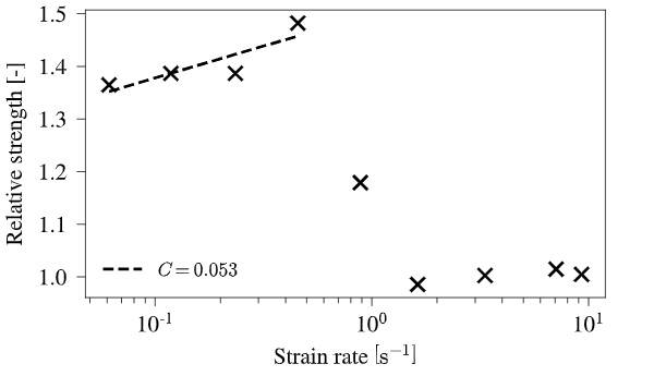
Simulation results with the additional seven loading rates are shown in Fig. 13 where the obtained failure loads are converted into relative strengths based on the reference strength and the loading rates intostrain-rates, under the assumption that E and ν remain unchanged. The failure model works as intended at the first four tested strain-rates, where a strain-rate constant of C= 0.053 is found, which corresponds to a relative deviation of 3.9% to the set value. After reaching the strain-rate of 4.6∙10-1s-1, the strength is unexpectedly decreasing down to the set reference strength even though the strain-rate is increasing. A detailed explanation for that needs to be found in the further development of this failure model, which until now only is in its initial state.
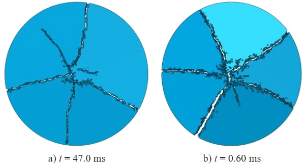
In Fig. 14 the simulated fragmentation that follows from the immediate element failure model are shown. Similar patterns and fragment sizes are obtained as with the smeared crack model even though a damage phase has not been implemented. Also, the number of fragments do not vary, which may be caused by the not obtained strength increase. This behaviour could again be explained by the application of a Butterworth-filter, as discussed for the smeared crack model, but Fig. 13 clearly shows that the drop in fracture strength is more systematically in this case.
An explanation for that is not found so far. By a closer look on the failure patterns, it is evident that due to the missing damage phase, the immediate element removal after reaching the fracture strength causes some instabilities. In the vicinity of the cracks, spurious element failures are seen that do not stem from the main cracks. Those arise from the created stress wave propagations.
In conclusion, the simple implementation of the immediate element failure model with a strain-rate dependent strength evaluation performs satisfactorily for a bending induced stress state considering its simplicity and the state of development. However, no focus has been given towards the directionality of a crack in an element nor the post-failure behaviour has been outlined in detail. Indeed, those characteristics need to be looked at in the further development to improve the performance of the failure model in capturing dynamic fragmentation of glass.
5. Outlook on future experimental work
Through the here presented project, it is the objective to improve the simulation of transient blast wave loads on thin-walled glass panes used in building facades. This not only requires the development of a material failure model that can account for strain-rate effects, as discussed in the previous section, but also the experimental characterisation of the dynamic mechanical properties of glass constitutes a fundamental part. As a blast wave from an explosion can be considered as a lateral load that is acting global on the entire glass surface, the failure is governed by bending induced tensile stresses. So far, most effort has been put into the research on the dynamic compressive strength as well as the split tensile strength of small cylindrical glass specimens.
However, a major lack is seen in the investigation of the dynamic flexural strength of soda-lime-silica glass. The investigations performed by Meyland et al. (2019a) were only on an initial level, and some issues regarding an upper limit of the loading speed with the used experimental setup were recorded together with a large scatter in the test results. More studies are needed to form the basis for a better understanding of how the flexural stress state affects the glass material at high strain-rates, which is required for the design of glass facades that have to mitigate the effect of a blast wave.
Depending on the problem to investigate several experimental techniques do exist for dynamic loading such as shock tubes (Osnes et al. 2018), drop weight towers (Acquaviva 1971), and flyer plate impact experiments (Rosenberg et al. 2008). Commonly, a split Hopkinson pressure bar testing device is used for the characterisation of dynamic material properties, which in general is build up by three main parts: (i) a loading device, (ii) bar components consisting of an incident bar and a transmission bar, and (iii) a data acquisition system (Chen and Song 2011). A specimen of the material to be tested is placed between the two bars and loaded in compression by means of a striker bar that is impacting the incident bar with a certain velocity depending on the desired strain-rate.
The loading history is then evaluated from strain signals measured on the incident bar and transmission bar, respectively. Nie et al. (2010) made some modifications in order to be able to test the dynamic equibiaxial flexural strength of borosilicate glass, by placing a small ring-on-ring test configuration in-between the bars. Usually, the fracture of glass happens over a very short time duration in the order of 10-3 seconds or even faster, which makes it hard to follow the fracture process with the naked eye before the specimen vanishes. In those situations, the application of high-speed cameras is preferable and opens up the opportunity to study the fracture process in more detail. However, when using the standard design of a split Hopkinson pressure bar setup together with a small ring-on-ring configuration, the specimen surfaces will be hidden by the bars.
In view of this, a modified design concept is developed for a ring-on-ring test configuration that is arranged in a novel split Hopkinson pressure bar inspired setup, where the transmission bar is transformed into a tube having the incident bar going through. An overview of the novel test setup with the main parts highlighted is given in Fig. 15. The load ring is mounted to the incident bar, and the support ring is attached to the end of the transmission tube with a through-going conical hole that exposes the tensile surface of the circular specimen.
This transformation not only allows a free view on the specimen but also reduces the total length of the setup considerably compared to the regular design of a split Hopkinson pressure bar setup. Moreover, it opens up the possibility to supplement the experiments with high-sped cameras where the recordings can be used for either studying the fractography or getting more details about the transient strains in the material by the use of digital image correlation (DIC).

The whole test setup is built on top of a 4.0 m long steel profile. The barrel, which is guiding the striker bar, has a length of 1.6 m, followed by the incident bar with a length of 2.0 m that is going through the transmission tube having a length of 1.35 m. The bar/tube material is chosen to be a high strength aluminium alloy in order to be able to achieve high impact velocities without reaching the yielding point of the material. The ring-on-ring test configuration is following the design guidelines given by the international standard ASTM C1499-15 (2015) and is intended for testing small circular glass specimens with a diameter of 45 mm and a thickness of 3mm. The contact diameter of the load ring is 18 mm, and to expose most of the tensile surface of the specimen the contact diameter of the support ring is dimensioned to 38 mm. Both rings are made with a tip radius of 2.5 mm. The applicability of the novel design concept has been numerically validated by Meyland et al. (2019b).
This testing device will be used to map the mechanical properties of soda-lime-silica glass at various high strain-rates, to get amore detailed picture of the strength development. In this paper, a linear logarithmic strength growth is assumed. Is this a sufficient assumption or will the strength increase form a plateau above a certain strain-rate due to the absence of the sub-critical crack growth as reported by Nie et al. (2010)? The future investigations will hopefully show!
6. Conclusions
An ongoing research project into the failure of glass at high strain-rates was presented by its two main parts: (i) numerical modelling of glass fracture, and (ii) the experimental investigation of soda-lime-silica glass at high strain-rates. Three different failure models using the element deletion technique in the finite element method were discussed and compared for their ability to capture the fragmentation of monolithic float glass in the simulation of a small ring-on-ring test setup. Moreover, the simulated loading curves were compared to existing experimental results regarding their ability to predict the fracture strength.
The performance of the JH-2 ceramic model was not promising regarding the prediction of the fracture strength. However, some realistically looking fracture patterns could be obtained for two of the three presented sets of model parameters. A more simple failure model initially developed for the crack simulation in concrete that is based on the smeared crack model, was capable of predicting fracture strengths comparable to experiments even though it is not born with a strain-rate dependency. The way it was handled in the simulation was that a specific fracture strength was assigned to the model that corresponds to the expected strain-rate in the glass material.
An increase in the number of fragments due to an increased fracture strength with loading-rate could not be captured by the simulations. It is concluded that the smeared crack model is too simple and not appropriate for the simulation of blast-related engineering problems due to the missing strain-rate dependency. Therefore, an initial step in the development of a simple failure model that includes a strain-rate dependent material strength has been proposed. As only an immediate element removal is applied, the model shows some instabilities where elements fail in areas that are not part of the main crack formation, due to stress wave reflections.
In the lower strain-rate regime, the assumed strength increase performs very well even though an increase in number of fragments as a function of the fracture strength is not seen. However, after a certain strain-rate, the strength is unexpectedly decreasing and a reason for that need to be found in the further development of the failure model. Common to all three presented failure models is that the element deletion technique has a high mesh dependency for the simulation of local cracking behaviour. For global quantities, such as forces acting on underlying structures or energy absorption by the material failure, this dependency may become less powerful.
The performed simulations were compared to a very limited number of dynamic flexural tests on monolithic soda-lime-silica glass. To improve and add more details to the existing knowledge, a novel developed test setup that is inspired by the well-known split Hopkinson pressure bar technique was presented and briefly explained for the flexural testing of glass at high strain-rates. The novelty lies within the bar-system, where the transmission bar is transformed into a tube having the incident bar going through. This modification not only reduces the total length of the setup considerably but also gives the opportunity to use high-speed imaging together with digital image correlation, as the tensile side of the specimen is free accessible in the ring-on-ring test configuration.
In the future, experimental results from the novel test setup will form the basis for the further development of the here presented initial step of a simple material failure model that includes strain-rate effects in the material strength. A special focus will be given to the computational time together with the precision for predicting the global structural response, as it is the intention of this project to develop a tool that can assist engineers in developing, designing and securing facades against extreme dynamic loads such as pressure waves from explosions.
7. Acknowledgements
The work presented in this paper is partly funded by the Innovation Fund Denmark (IFD) under File No. 8053-00088B, Rambøll Fonden under File No. 2018-51, and the Danish engineering consultancy Ramboll Denmark A/S, Private & Public Buildings East.
8. References
Acquaviva, S.J.: A drop weight test for the impact strength of ceramic materials. Mater. Res. Stand. 11, 21–22, 47 (1971)
ASTM C1499-15: Standard Test Method for Monotonic Equibiaxial Flexural Strength of Advanced Ceramics at Ambient Temperature. ASTM International, West Conshohocken, PA (2015)
Belytschko, T., Lu, Y.Y., Gu, L.: Crack propagation by element-free Galerkin methods. Eng. Fract. Mech. 51, 295–315 (1995). doi: https://doi.org/10.1016/0013-7944(94)00153-9
Bønding, C.K.T., Meyland, M.J.: Properties of Float Glass at High Strain Rates (MSc Thesis). Technical University of Denmark, Department of Civil Engineering (2017)
Camacho, G.T., Ortiz, M.: Computational modelling of impact damage in brittle materials. Int. J. Solids Struct. 33, 2899–2938 (1996). doi: https://doi.org/10.1016/0020-7683(95)00255-3
Chen, W., Song, B.: Split Hopkinson (Kolsky) Bar. Springer US, Boston, MA (2011)
Griffith, A.A.: The Phenomena of Rupture and Flow in Solids. Philos. Trans. R. Soc. A Math. Phys. Eng. Sci. 221, 163–198 (1921). doi: https://doi.org/10.1098/rsta.1921.0006
Haldimann, M., Luible, A., Overend, M.: Structural Use of Glass. International Association for Bridge and Structural Engineering, Zürich, Switzerland (2008)
Hillerborg, A., Modéer, M., Petersson, P.-E.: Analysis of crack formation and crackgrowth in concrete by means of fracture mechanics and finite elements. Cem. Concr. Res. 6, 773–781 (1976). doi: https://doi.org/10.1016/0008-8846(76)90007-7
Holmquist, T.J., Johnson, G.R., Grady, D.E., Lopatin, C.M., Hertel, E.S.: High strain rate properties and constitutive modeling of glass. In: 15th International Symposium on Ballistics. , Jerusalem (1995)
Hooper, P.A., Sukhram, R.A.M., Blackman, B.R.K., Dear, J.P.: On the blast resistance of laminated glass. Int. J. Solids Struct. 49, 899–918 (2012).doi: https://doi.org/10.1016/j.ijsolstr.2011.12.008
Irwin, G.R.: Analysis of stresses and strains near the end of a crack traversing a plate. J. Appl. Mech. 24, 361–364 (1957)
Johnson, G.R., Holmquist, T.J.: An improved computational constitutive model for brittle materials. In: AIP Conference Proceedings. pp. 981–984. AIP (1994)
Johnson, G.R., Stryk, R.A., Beissel, S.R., Holmquist, T.J.: An algorithm to automatically convert distorted finite elements into meshless particles during dynamic deformation. Int. J. Impact Eng. 27, 997–1013 (2002). doi: https://doi.org/10.1016/S0734-743X(02)00030-1
Kuntsche, J.K.: Mechanisches Verhalten von Verbundglas unter zeitabhängiger Belastung und Explosionsbeanspruchung. Springer Berlin Heidelberg, Berlin, Heidelberg (2015)
Larcher, M., Solomos, G., Casadei, F., Gebbeken, N.: Experimental and numerical investigations of laminated glass subjected to blast loading. Int. J. Impact Eng. 39, 42–50 (2012). doi: https://doi.org/10.1016/j.ijimpeng.2011.09.006
Del Linz, P., Hooper, P.A., Arora, H., Wang, Y., Smith, D., Blackman, B.R.K., Dear, J.P.: Delamination properties of laminated glass windows subject to blast loading. Int. J. Impact Eng. 105, 39–53 (2017). doi: https://doi.org/10.1016/j.ijimpeng.2016.05.015
Meyland, M.J., Bønding, C.K.T., Eriksen, R.N.W., Nielsen, J.H.: An experimental investigation of the flexural strength of soda–lime–silica glass at high loading rates. Glas. Struct. Eng. 4, 175–183 (2019)(a). doi: https://doi.org/10.1007/s40940-018-0089-2
Meyland, M.J., Eriksen, R.N.W., Nielsen, J.H.: A novel full-view split Hopkinson pressure bar technique for flexural testing. In: Ren, F., Wu, C., and Lok, T.S. (eds.) 13th International Conference on Shock & Impact Loads on Structures. pp. 371–380. CI-Premier Pte Ltd, Singapore (2019)(b)
Moës, N., Dolbow, J., Belytschko, T.: A finite element method for crack growth without remeshing. Int. J. Numer. Methods Eng.46, 131–150 (1999). doi: https://doi.org/10.1002/(SICI)1097-0207(19990910)46:1<131::AID-NME726>3.3.CO;2-A
Nie, X., Chen, W.W., Templeton, D.W.: Dynamic Ring-on-Ring Equibiaxial Flexural Strength of Borosilicate Glass. Int. J. Appl. Ceram. Technol. 7, 616–624 (2010). doi: https://doi.org/10.1111/j.1744-7402.2010.02508.x
Nie, X., Chen, W.W., Wereszczak, A.A., Templeton, D.W.: Effect of Loading Rate and Surface Conditions on the Flexural Strength of Borosilicate Glass. J. Am. Ceram. Soc. 92, 1287–1295 (2009). doi: https://doi.org/10.1111/j.1551-2916.2009.03019.x
Norville, H.S., Harvill, N., Conrath, E.J., Shariat, S., Mallonee, S.: Glass-Related Injuries in Oklahoma City Bombing. J. Perform. Constr. Facil. 13, 50–56 (1999). doi: https://doi.org/10.1061/(ASCE)0887-3828(1999)13:2(50)
Osnes, K., Børvik, T., Hopperstad, O.S.: Testing and modelling of annealed float glass under quasi-static and dynamic loading. Eng. Fract. Mech. 201, 107–129 (2018). doi: https://doi.org/10.1016/j.engfracmech.2018.05.031
Osnes, K., Holmen, J.K., Hopperstad, O.S., Børvik, T.: Fracture and fragmentation of blast-loaded laminated glass: An experimental and numerical study. Int. J. Impact Eng. 132, 103334 (2019). doi: https://doi.org/10.1016/j.ijimpeng.2019.103334
Pelfrene, J.: Numerical Analysis of the Post-Fracture Response of Laminated Glass under Impact and Blast Loading (PhD Thesis).Department of Materials Science and Technology, Ghent University (2016)
Pelfrene, J., Van Dam, S., Van Paepegem, W., Degrieck, J.: Numerical simulation of elastic, fracture and post-failure response of monolithic and laminated glass under impact loading.In: Belis, J., Louter, C., and Mocibob, D. (eds.) COST Action TU0905 Mid-term Conference on Structural Glass. pp. 413–420. CRC Press (2013)
Pelfrene, J., Dam, S. Van, Sevenois, R., Gilabert, F., Paepegem, W. Van: Fracture Simulation of Structural Glass by Element Deletion in Explicit FEM. In: Challenging Glass 5 (CGC5) -Conference on Architectural and Structural Applications of Glass. pp. 439–454 (2016)(a)
Pelfrene, J., Kuntsche, J., Van Dam, S., Van Paepegem, W., Schneider, J.: Critical assessment of the post-breakage performance of blast loaded laminated glazing: Experiments and simulations. Int. J. Impact Eng. 88, 61–71 (2016)(b). doi: https://doi.org/10.1016/j.ijimpeng.2015.09.008
Peroni, M., Solomos, G., Pizzinato, V., Larcher, M.: Experimental Investigation of High Strain-Rate Behaviour of Glass. Appl. Mech. Mater. 82, 63–68 (2011). doi: https://doi.org/10.4028/www.scientific.net/AMM.82.63
Rosenberg, Z., Ashuach, Y., Dekel, E.: More on the behavior of soda lime glass under shock loading. Int. J. Impact Eng. 35, 820–828 (2008). doi: https://doi.org/10.1016/j.ijimpeng.2007.09.002
Rudick, M.M., Norville, H.S.: Glass-Related Injuries in Oklahoma City Bombing. J. Perform. Constr. Facil. 14, 167–167 (2000). doi: https://doi.org/10.1061/(ASCE)0887-3828(2000)14:4(167)
Smith, D.: Glazing for Injury Alleviation Under Blast Loading –United Kingdom Practice. In: Glass Processing Days. pp. 335–340 (2001)
Song, J.H., Wang, H., Belytschko, T.: A comparative study on finite element methods for dynamic fracture. Comput. Mech. 42, 239–250 (2008). doi: https://doi.org/10.1007/s00466-007-0210-x
Unosson, M., Olovsson, L., Simonsson, K.: Failure modelling in finite element analyses: Element erosion with crack-tip enhancement. Finite Elem. Anal. Des. 42, 283–297 (2006). doi: https://doi.org/10.1016/j.finel.2005.07.001
Wiederhorn, S.M.: Influence ofWater Vapor on Crack Propagation in Soda-Lime Glass. J. Am. Ceram. Soc. 50, 407–414 (1967). doi: https://doi.org/10.1111/j.1151-2916.1967.tb15145.x
Wiederhorn, S.M., Bolz, L.H.: Stress Corrosion and Static Fatigue of Glass. J. Am. Ceram. Soc. 53, 543–548(1970). doi: https://doi.org/10.1111/j.1151-2916.1970.tb15962.x
Zhang, X., Hao, H., Ma, G.: Laboratory test and numerical simulation of laminated glass window vulnerability to debris impact. Int. J. Impact Eng. 55, 49–62 (2013)(a). doi: https://doi.org/10.1016/j.ijimpeng.2013.01.002
Zhang, X., Hao, H., Ma, G.: Parametric study of laminated glass window response to blast loads. Eng. Struct. 56, 1707–1717 (2013)(b). doi: https://doi.org/10.1016/j.engstruct.2013.08.007
Zhang, X., Hao, H., Ma, G.: Dynamic material model of annealed soda-lime glass. Int. J. Impact Eng. 77, 108–119 (2015). doi: https://doi.org/10.1016/j.ijimpeng.2014.11.016
Zhang, X., Zou, Y., Hao, H., Li, X., Ma, G., Liu, K.: Laboratory Test on Dynamic Material Properties of Annealed Float Glass. Int. J. Prot. Struct. 3, 407–430 (2012). doi: https://doi.org/10.1260/2041-4196.3.4.407
Zhou, X.Q., Wang, M.Y., Li, L.X.: Dynamic damage assessment of float glass under blast loading. Adv. Struct. Eng. (2019). doi: https://doi.org/10.1177/1369433219845691