First presented at GPD 2017
Our main objectives were to design, develop manufacture and test a completely transparent slender walkway, having the particularity of being self-bearing. The starting point for the design has been the good behaviour of pre-stressed beams in terms of load capacity.
Special care has been taken during the design state to fulfil five safety requirements: resistance, retention, redundancy, postbreakage resistance and standard regulations. For the design and verification of the model, analytic structural calculation as well as a finite element model have been carried out.
The effect of different pre-stress loads and buckling behavior of the element has been studied, obtaining the relationship between load capacity, deflections, maximum tensional stress in the glass and design parameters. [1]
Finally, a full glass prototype has been manufactured and tested. During the loading stage, test deformation and the evolution of stress in glass has been monitored and measured using a polariscope.
The glass element has been led to breakage to validate the expected data of the design phase and obtain relevant information regarding the post-breakage behaviour. Load was increased up to 2.5 times design load to reach the breakage state and to hold 1.4 times the design load once reached the collapse state for 12 hours.
Introduction
This research is the result of several years of study of glass beams, analyzing the problems with the brittle breakage and the safe postbreakage behaviors.
The aim of this study is the design of a self-bearing pre-stressed glass element that achieves the features of maximum transparency and keeps a post-breakage capacity to be used in the field of architecture. For this purpose, there will be inserted a prestressed reinforcement steel [2] and a ribbed section shape (that results from an optimized and evolved design). (See Figure 1)
Design and geometry
The solid beam as concept is only used as a calculation model. Laminated beam will be used as many examples of skylight glass beams enhancing its transparency. Reviewing the state-of-the-art, we can say that the insertion of a pre-stressed reinforcement element will provide a safe breakage beam and a bigger load capacity [3] and against breakage.
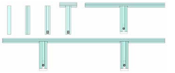
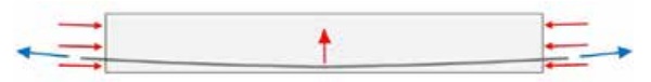
In the first step of the evolved design, the beam will be compound of several laminated glass plies to keep them joined and to include a redundant or sacrifice leaf in case of breakage. The intermediate glass leaf is trimmed to place a steel rod. This rod will receive a strain of tensile from both ends that compresses the glass plies conferring bigger resistance (increasing the compressed areas and decreasing the tensile areas); otherwise, it increases the safety due to the reinforced steel rod that avoids glass fragments falling down. Because of the pre-stress applied, these fragments will be held together.
The effect of pre-stressing in the laminated section provides lateral buckling; in order to avoid this effect a T shape will be obtained with an a bespoke recess in the joint detail. This T shape will increase the inertia.
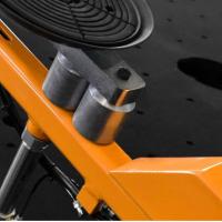
The design will be optimized if the intermediate glass leaf is trimmed with a longitudinal curve shape to avoid the deflection due to the dead loads when the pre-stressing is applied. The linear gap confines the rod laterally. (See Figure 2)
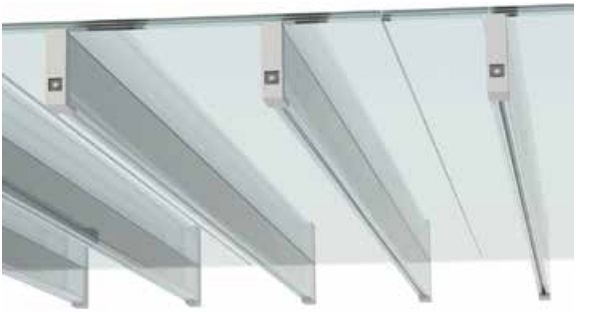
On the other hand, if the wings of the T become bigger to support a uniform distributed load a problem could arise in the joint knot between the horizontal and vertical element obtaining an unstable element as well; to avoid this issue, the section of the T shape is doubled in TT shape solving the problem [4]. In this case, the moment diagram would work as a continuous beam over the ribs (and therefore in a very optimized way) getting a better stability as a prefabricated element easy to transport and install.
Finally, the design could be improved by adding an anti-slip layer of thin glass with more impact resistance (3mm toughened plate). Also, it can be used as a sacrifice layer to be removed when scratched or broken. It would be better if all glass layers were low-iron glass. The self-bearing prefabricated element has a modular character to create slabs. There can be attached elements in 2 directions over a net of 6x6 m. The ribs are located in such a way that the distances between them are the same when more elements are joined. (See Figure 3)
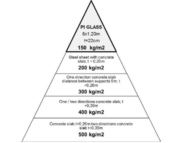
The isostatic glass slab weight is on the top of the pyramid in respect to the slenderness and lightness parameters regarding other slabs for the same loads. (See Figure 4)
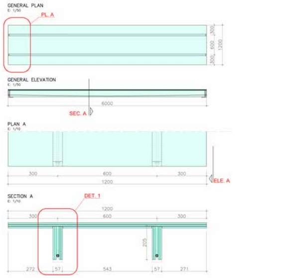
The general geometry is 6.00mX1.2m, length due to the common length of fabrication and width because of half width of a box of a truck. The height of the element does not have precedent in this kind of structural glass element, L/30, reducing the height and the effect of buckling [5]. Other researches use double height, around L/15. (See Figure 5)
Hypothesis and bases of calculation
We have adopted the bases of calculation for the glass plate for all the methods of calculation, so they will be performed for the scale 1:2 which will be the scale of the test sample: The dead load of the π glass plate at scale 1:2 is 1,10kN and the live load is 5kN/m2. The limit of the deflection will be L/500 since we need to ensure the feeling of stability.
The admited calculation strain according to prEN 16612 will be 14.25 Mpa, according to the type of glass (annealed glass), the surface treatment (without treatment), the type of load (permanent), and the lasting of time (load with peaks as much as 11 hours continuosly). To justify the change of the scale in the 3 methods we have to hold the hypothesis that glass always breaks at the same strain in any scale and the deflections are proportional for the same loads.
For simulating the uniform distributed load will be replaced by 2 supports located at L/4 from the ends to obtain a similar moment with a deflection that varies less than 10%.
Checking by analytic calculation
For the analytic calculation, the element is simplified to half section "T" shaped with the same properties in terms of geometry, thickness and compression efforts on the ribs. The hypothesis in this case is that the glass board and ribs are working together monolithically as a single element.
Hypothesis
Distance between supports: L= 3.00 m
Width of load: B= 0.60 m
Distributed load: q= 5 kN/m2
Linear load: q= 3 kN/m
Point load: F = 4.5 kN
Position of load: (L/4) a= 0.75 m
Pre-stress: N1= 7.5kN; N2= 10 kN
Vertical load: V1= 0.15kN; V2= 0.2kN
Geometry data
Height of beam: H1= 100 mm
Width of beam: b1= 30 mm
Height of glass pane: H2= 10 mm
Width of glass pane: b2= 300 mm
Inertia: Ix= 706.25 cm4
Resistance module: 1 W1= 91.13 cm3
Resistance module: 2 W2= 217.3 cm3
Area: A= 60 cm2
Elasticity Modul: E=73,000 Mpa
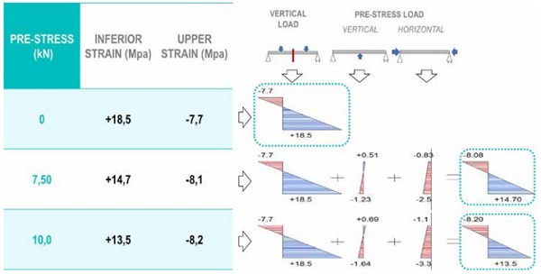
For developing the analytic calculation, we start with a vertical load and a normal compression load on the ribs. This compression load is performed through a tensile rod with a curved shape, generating a vertical force against the vertical load. (See Figure 2)
If the efforts of these actions are included in the strain graphics of the “T” shaped beam sections, we obtain the results shown below on the left where tensile strain decreases with pre-stressing to improve the glass behavior. (See Figure 6)
Checking by FEM simulation
For FEM simulation there have been performed several hypothesis and premises to be close to the real test. The load is modeled on a surface of 2 cm in the whole width of the board and the total load is distributed on this surface.
The supports are simulated on a lower line on the ribs to avoid distortions in the results; there will be single supports allowing the turns and limiting the 3 displacements in one of the ends and 2 displacements in the opposite one to allow the expansion and the action of the pre-stressing.
For simulating the pre-stressing, load is located on the surface of the section of both ends.
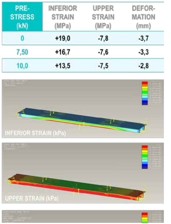
The strains will be monitored at the middle point of the upper surface of the board, in the lower area of the ribs and the deflections related to different load steps for the 3 cases of comparison:
Without compression, compression of 15kN and compression of 20 kN. The data for the design load is 9kN. (See Figure 7)
Checking by tests
First of all, we make several changes to adapt the glass plate to scale 1:2., based on the results of the state-of-art [6]. Glass: Extra clear is replaced by clear float Glass board: laminated 10+10+10 is replaced by 10+5 allowing the curing of the UV adhesive through the 10mm monolithic glass. Ribs: Glass pane 19 is replaced by 10 because it is the more similar thickness and it allows the insertion of an 8mm rod. Layer/ Adhesive: SGP layer is replaced by PVB and UV adhesive. Tensile rod: S275JR steel Ø16mm rod is changed by Ø8mm rod.
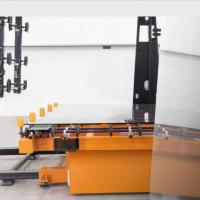
The square shoes of support and pre-stressing keep proportional in thickness and geometry. Assembly π glass plate: The glass ribs will be located in the boxes of the glass board keeping a perpendicular manner and will be adhered with Panacol Vitricol UV. The lamp used is Panacol S 255 WT with the same brand of Vitralit. This UV adhesive reach stresses up to 23 MPa.
After this, we have to pre-stress the Ø8mm tensile rods locating them into the gap created of 10mm and pre-stressing against the square shoes. In this case, the misaligned problems will be multiplied if the design of the ending elements are very complex. Pre-stressing of 7.5kN and 10kN are applied in each tensile rod that means 3/5 and 4/5 of its elastic limit. To perform the test we have designed a selfbearing and a test bench.
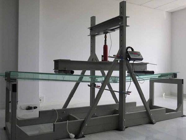
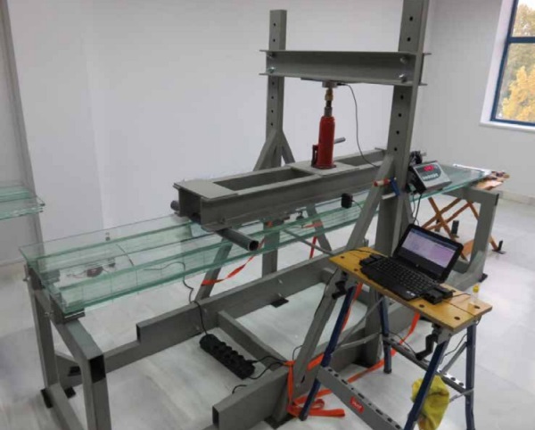
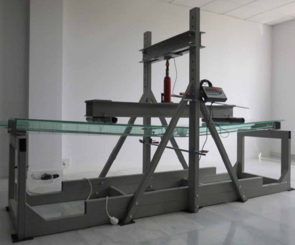
The measurement devices will be as follows: a load cell with digital screen, a comparator clock with articulated arm, a digital caliper, a polarimeter with specific software and a hydraulic jack as load applicator. (See Figure 8)
Finally, the test process with the load phase in the elastic period was performed as follows: The π glass plate with dimensions 3.00m X 0.60m will support a uniform distributed load of 5 kN/ m² that means a single load of 9 kN split in two single loads at 1/4 and 3/4 from the ends with several steps of loads along 3 minutes by load step. After this, the load will be increased up to 9 kN x 1.5 =13.5 kN as safety test.
There will be performed 3 load tests with 3 different conditions: pattern test without pre-stress, 15kN pre-stress test (7.5kN each tensile rod) and 20 kN pre-stress test (10kN per tensile rod). In each of the 3 tests, several data there will be monitored: the lower stress in the middle of the span in one of the ribs, the upper strains on the glass board and the deflection.
Extracted results
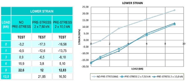
Results of tensile on the low point of the rib
The gap between the yellow graphic and the orange and red ones is due to the first step of pre-stress. However, there is a short difference between two pre-stressed steps, that means it would have been suitable to apply increase the difference between pre-stress loads for improving the results. In the case of a non-pre-stressed beam, it has not been carried out a safety test because there was a big breakage risk overcoming the calculation resistance. (see Figure 9)
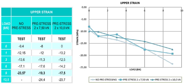
Results of tensile from the upper point over the glass board
There has been checked the stress on the laminated glass board according to the polarimeter: it is 7 MPa due to the pressure and temperature in the laminated process. The highest value of the compression stress is exactly from ribs without pre-stress because this is not balanced for any compression in the lower part and therefore it has highest values in tensile stress (below) and compression stress (upper). (See Figure 10)
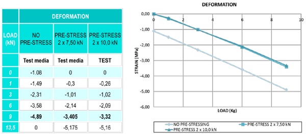
Results of deflections
The deflection in the case of non-pre-stress is almost 50% in respect to the pre-stressed ones and there is a short difference between them. The constant created between the lines is almost parallel and is due to the contra deflection acquired in the process of prestress. (See Figure 11)
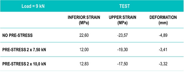
Differences among test results with different pre-stress
Pre-stress improves mainly lower tensile stress and therefore also its resistance and breakage risk. The effect of pre-stressed causes a reduction of the upper stresses that means improving these stresses. Deflections are also improved giving stiffness and stability feeling. The big jump of improving in the lower stress and deformation are achieved in great amount with the first step of pre-stressing. The second step of pre-stressing confirms the trend but does not improves according to pre-stress increasing. (See Figure 12)
Post-breakage behaviour (non-elastic period)
This test of post breakage behavior is performed with a simulation of uniform distributed load (4 points) with a 20 kN of pre-stressing (10 kN per rib). There are different phases in the breakage and also there are 2 rules from the state-of-the-art that says than with the first crack in the lower part in a test of 4 point is considered breakage; when the first crack appears in the upper part of the board that is considered collapse. We are going to differentiate 3 phases: elastic period until breakage, and non-elastic period with breakage with loadbearing for some time and with collapse with loadbearing for some time. In the first step the deflections are proportional to the loads in the elastic period:
The design load of 9 kN is reached with deflection of 3.3 mm
The safety load (1.5 x 9=13.5kN) is reached with deflection of 5.2 mm
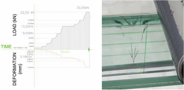
The breakage is reached up to 22.5 kN (2.5 times design load) when the first crack appears in the lower part of the rib. (See Figure 13)
Breakage phase
This crack in “V” shape is repeated until 3 times in an identic way in the same rib. This crack is characteristic extending in horizontal in the upper area because is the more compressive area.
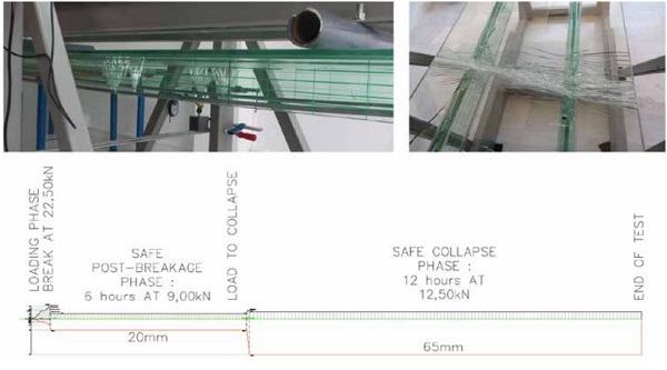
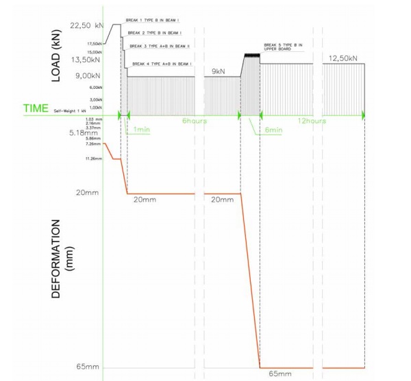
The crack does not reach the upper area and the reinforcement steel rods avoid the element from going down. Once the safety load is reached (22.5 kN) and cracks appear sequentially in the same way, so at the same time the element is going unloading until the stabilization at the load of 9kN (the design load by coincidence) with a deflection of 20mm (6 times bigger than without breakage) and keeping in this way for 6 hours when we decided to lead it to the collapse. (See Figure 14)
Collapse phase
After post-breakage phase, the phase of collapse begins when the first crack appears on the upper surface of the board [7]; this is considered unsafety. That means although the sample was not collapsed keeping itself due to the adherence of glass panes and the rods of pre-stressed with all the layers broken, it is considered unsafety.
In the test, the first crack on the horizontal surface appears at the load of 15 kN; in that moment, we stopped applying the load and decreased until 12.5 kN where it will be kept by itself with a deflection 65mm for 12 hours; in that moment we considered the end of the test. In this final figure, we can see how the test sample has finished the test after the loads supported and the lack of the visible collapse holding a load of 1.4 times the design load with an extension of deflection [8] of L/50 approximately. (See Figure 15)
Conclusions and summary:
General
The prefabricated PI shaped glass plate has demonstrated its ability and safety postbreakage to become a reliable element for applying in the field of architecture. The structural element achieved gets bigger transparency with less glass due to a slender section more optimized thanks to prestressing.
Methodological conclusions
The test at scale confirms the analytic calculation results and the results coming from the FEM simulation within the elastic period and therefore the method is right. Test let to characterize the post-breakage behavior, impossible from the analytic study.
From materials
The adhesive technology and its efficiency has been demonstrated without increasing unknowns even in the limit situation of breakage keeping the UV adhesive unalterable. Steel alternatives with more resistance will imply a more slender design.
Structural range
The pre-stressing designed improves the strains and the deflections of the glass plate and it is a way to optimize the sections achieving greatest slender. The weight per square meter is lighter for supporting the same load than the lightest steel or concrete slab.
Experimental range
The results have demonstrated safety against the breakage when is applied a pre-stressing decreasing the tensile at the lower area and getting smaller deflections. It is possible to increase the pre-stressing if we improve the quality or even if the section of the rod is increased.
Since the breakage has reached 2.5 times the design load, with this result, we have achieved a safety collapse under our point of view. The box in the lower part of the board has controlled the lateral buckling of the ribs coming from due to compression effect and the deflection due to the loads.
It is significant the importance of keeping the design load of 9.00kN/m2 since the breakage for 6 hours and keeping for 12 hours the collapse phase with 1.4 times the design load. Finally, it has been shown a high level of breakage safety and we have achieved to take a little step forward against the brittleness of glass [9]. (See Figure 16)
References:
[1] AMADIO, C., & BEDON, C. (2010). Buckling of laminated glass elements in out-of-plane bending. Engineering Structures(32), 3780-3788.
[2] CUPAC, J., MARTENS, K., NUSSBAUMER, A. ET AL. Glass Struct Eng (2017) 2: 3. doi:10.1007/s40940-017-0038-5
[3] BOS, F. P.; VEER; F.A.; HOBBELMAN, G.J. ; LOUTER P.C. (2008). Stainless steel reinforced and post-tensioned glass beams. Recuperado el 7 de Abril de 2008
[4] VEER, F. (2007). Walking on air, designing and engineering a glass bridge. Glass Performance Days (pp. 244-246). Tampere, Finnland: GPD.
[5] LOUTER, C., BELIS, J., VEER, F., & LEBET, J. (2012). Structural response of SG_Laminated reinforced glass beams; experimental investigations on the effects of glass type. Engineering Structures (36), 292-301.
[6] LOUTER, C. (2007). Experimental research on scale 1:4 models of an 18m reinforced glass beam, part i. Glass Performance Days 10th International Conference on Architectural and Automotive Glass. Tampere, 87-92.
[7] LOUTER, C. (2013). Reinforced and Post-tensioned Glass Beams. Tampere: GPD.
[8] MARTENS,K; CASPEELE,R; BELIS, J (2015). Development of composite glass beams – A review. DOI: https://doi.org/10.1016/j.engstruct.2015.07.006
[9] MARTENS,K; CASPEELE,R; BELIS, J (2015). Development of Reinforced and Posttensioned Glass Beams: Review of Experimental Research. DOI: http://dx.doi.org/10.1061/(ASCE)ST.1943-541X.0001453
Acknowledgements:
The authors gratefully acknowledge the support provided by Ariño Duglass, Laguna Belvis and ENAR team.