Authors: Matyas Gutai, Shwu-Ting Lee, Bumpei Magori, Yu Morishita, Abolfazl Ganji Kheybari and Joshua Spencer
Source: Journal of Facade Design and Engineering, 8(2), 127–152.
DOI: https://doi.org/10.7480/jfde.2020.2.4784
Abstract
Water-filled building envelopes are hybrid constructions with a solid and a fluid component, typically a glass or steel shell filled with water. The paper introduces the challenges of developing a water-filled façade structure and evaluates the possibility to utilise it as a viable construction system on a building scale. Water-filled glass (WFG) has been researched in the past and it was presented as an independent window element of a conventional building, where energy savings are achieved by using the absorption of the water layer for energy management of the building envelope. The results suggest that WFG’s efficiency could be improved further if the system is assembled as a united building envelope in which the fluid can flow between panels and building parts. The paper presents two experimental ‘water house’ buildings with these design parameters, designed and constructed by the author. The importance of these buildings is that a connected water-filled envelope is built for the first time. The discussion presents two construction methods for water-filled façades, evaluates their viability for different climates, introduces the design-construction aspects of the technology, and offers a comparison with existing construction methods.
A fluid-solid building envelope provides significant savings for both operational and embodied energy, by lowering cooling load, reusing absorbed heat, balancing thermal differences between parts of the envelope and the rest of the building, while making additional construction elements (e.g. external shadings) obsolete.
1 INTRODUCTION
Structural materials have a significant impact on the ecological footprint of the built environment. This applies specifically to building envelopes that play a main role in energy efficiency and thermal comfort in a building. In particular, building envelopes with high window-to-wall ratios (WWR) are a good example, as glass façades utilise energy intensive materials (Adalberth, 1997) and increase operational energy demand (Gasparella, Pernigotto, Cappelletti, Romagnoni, & Baggio, 2011). Innovations in glass envelopes have great potential for positive change in the environmental impact of buildings, especially if they are able to lower both embodied and operational energy. This is especially the case where higher life-cycle assessment (LCA) is reported for zero energy buildings compared to low energy constructions (Ramesh, Prakash, & Shukla, 2010), which is mainly due to the increased embodied energy component (i.e. added PV or solar panels) of the former when compared to the latter. This implies that there is a need for innovations that can improve energy performance without an increase in embodied energy.
In terms of the energy management of building envelopes, the current state of research on optically clear windows can be divided into four groups. The first category addresses solar gain (SHGC) with coating, dynamic or active glazing. Solutions for this include Low-E coating (Cui & Mizutani, 2016), electrochromic glazing or EC (DeForest et al., 2015), suspended particle device glazing or SPD (Ghosh, Norton, & Duffy, 2016) and polymer dispersed liquid crystal or PDLC (Hemaida, Ghosh, Sundaram, & Mallick, 2020). The second category is to improve the thermal resistance (U-value) of the building envelope, like multi-layered glazing (Arici, Karabay, & Kan, 2015). The third approach is to reduce cooling demand with shading (Tao, Jiang, Li, & Zheng, 2020). Finally, the last solution is to utilise a fluid medium, i.e. ventilated air stream in the glazing, which can, for example, cool the glass itself using outside air or be used to preheat the air before it enters the interior space (Ismail, Salinas, & Henriquez, 2009). An alternative to circulating air is utilising a “circulating water chamber”, which has the benefit of capturing solar energy and turning that potential energy load into a renewable energy source (Chow, Li, & Lin, 2010).
Since the fluid-glass system has been introduced (Gutai, 2010) and was patented by the author (P 11 00 156, 2011; 6250530, 2012; EP2689192A2, 2012), the technology has been researched by different research groups. Among these, an important development was to establish a correlation between the intensity of pumped water flow in the cavity and the characteristics of the window (U-value and SHGC), which also showed that these values can be tailored to external conditions (Sierra & Hernández, 2017). In terms of energy consumption, a comparison of standard window with WFG in Hong Kong was presented (Chow, Li, & Lin, 2011a). A different approach was shown for a Madrid case, where WFG had a stable water temperature to lower energy demand for heating and cooling (Gil-Lopez & Gimenez-Molina, 2013). Additional research included energy simulation for annual energy demand in humid climates (Li & Chow, 2011), analysis on impact of solar angle (Chow, Li, & Lin, 2011b), evaluation of headers (Chow & Lyu, 2017), and performance in different climates in China (Lyu, Chow, & Wang, 2018).
These research projects present the technology as one window placed in a conventional building envelope. In addition to these, the author designed and built experimental buildings titled Water House 1.0 or WH01 (Gutai, 2015) and Water House 2.0 or WH02 ((“Experimental - Future Projects - 2017 | World Architecture Festival,” 2017), which explore the potential of connected building envelopes in which the water infill is allowed to flow between panels and building parts. The importance of this approach is the enhanced thermal, energy, and structural performance that resulted from water flow, as introduced in book Trans-structures (Gutai, 2015). The hybrid structure of WFG lowers energy consumption without increasing embodied energy as the water infill itself has low environmental impact when compared to other building materials. The two buildings also present two different construction methods: Structure Insulated Panel (SIP) and frame+infill system. The results of these structural developments are the key focus of this paper as they are essential for the development of an integrated WFG construction system that goes beyond the limitations of a single window.
2 METHODOLOGY
The paper presents an experimental research approach to the problem of developing continuous hybrid water-filled building envelopes through design and construction. These buildings are introduced in Chapter 3. The structural challenges specific to this technology are evaluated through tests introduced in Chapter 4 and 5.
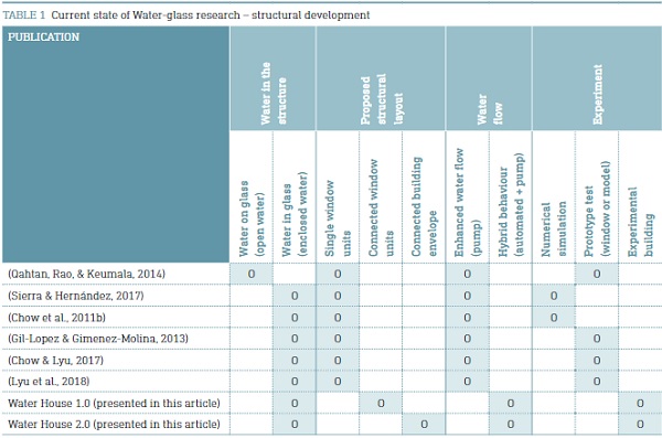
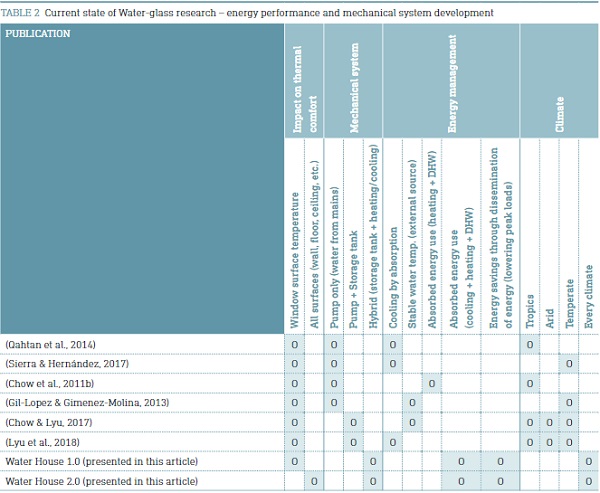
The importance of this exploration is twofold. Firstly, developing the technology from a window to a continuous envelope improves its performance: lower energy consumption (54 – 72% savings compared to double glazing and 34 - 61% compared to triple glazing) (Gutai & Kheybari, 2020), reduced energy demand due to smaller temperature differences within the building (water flow would disseminate energy gains within the building), (Gutai & Kheybari, 2021) and improved thermal comfort (water inside WFG can be heated/cooled for better Mean Radiant Temperature /MRT/). Secondly, the tests and analysis of the system are important because this particular kind of envelope was built for the first time, which had an impact on material use, manufacturing, assembly, and the integration of various functions (i.e. heating, cooling, solar absorption, etc.) into one construction system. The novelty of WH01 and WH02 is shown in Table 1 and Table 2, which present the structural and energy development of water-filled envelope projects.
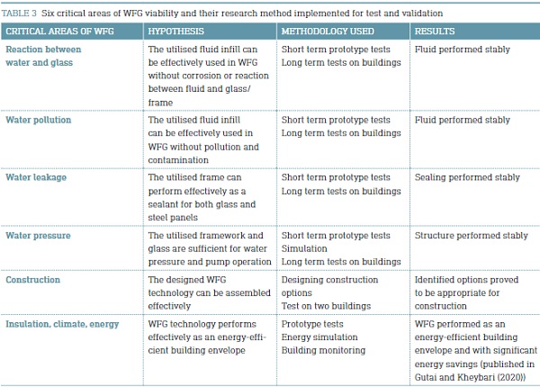
The two prototype houses served as experimental buildings to identify, resolve, and test the critical aspects for viability of WFG technology. The research identified six critical areas, which were explored over the course of five years research. Table 3 shows these areas and the methodologies involved.
3 WATER HOUSE CONSTRUCTION
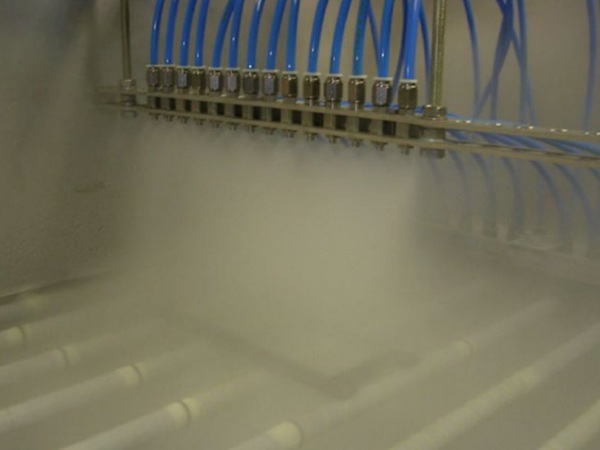
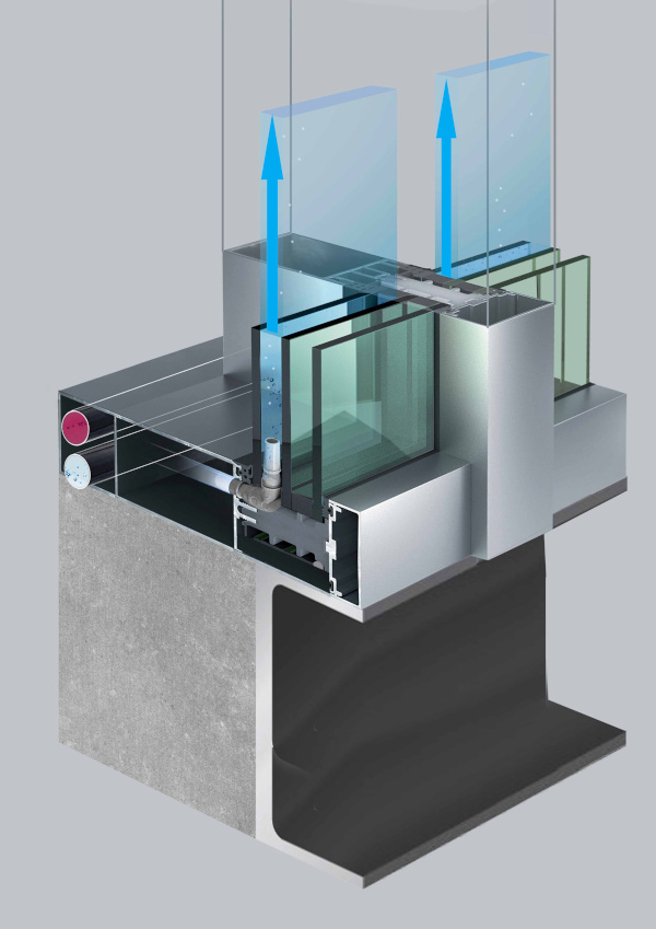
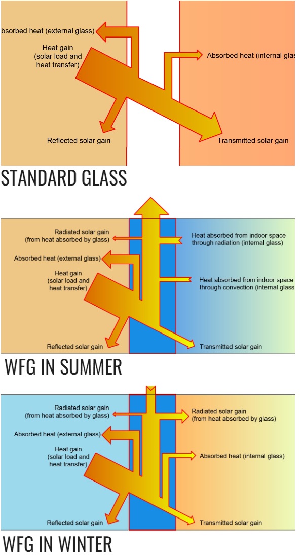
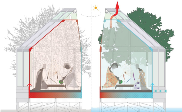
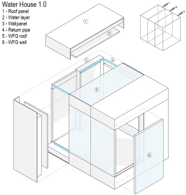
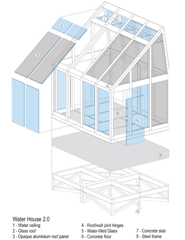
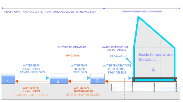
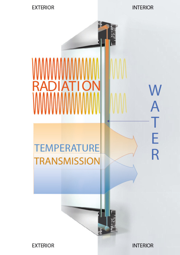
WFG can be built as individual window unit or as a connected building envelope. The first type is basically a heat absorbing heating/cooling unit, which benefits from the absorption of water as shown in Fig. 2. This solution is described as “fluid-glass” or “water-glass” and operates with a pump and stable flow. The second type is titled water house construction, which is built as a set of panels that are connected to each other, as shown in Fig. 1 and Fig. 3. The panels are connected in a closed loop, which is typically formed by two opposite wall surfaces and floor + ceiling/roof panel in-between (as shown in Fig. 3).
Both options absorb heat which can be transported to a thermal storage unit, as shown in Fig. 3. A pump requires less energy than cooling or heating the space, which leads to direct energy savings. In addition, water house construction can distribute energy within the envelope, which increases energy savings further by exchanging energy between overheated and cold areas of a building (e.g., north-south façade, lower-upper building parts).
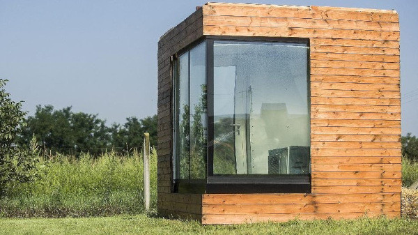
3.1 WATER HOUSE 1.0 PAVILION
The first Water House construction was built in Kecskemet, Hungary. The pavilion consisted of 4 water-filled glass (WFG) and 13 water-filled steel (WFS) panels, shown in Fig. 4. The WFS panel had 20 cm insulation and the WFG had an external argon layer. Pipework and cables were placed in maintenance gaps between wall panels and the floor (shown in Fig. 20), to protect them from impact of the cold climate (Köppen-Geiger D - heating dominated). Solar absorption of water was used to lower energy consumption for cooling and heating. This approach was validated in our previous publication (Gutai & Kheybari, 2020) with 61% savings compared to double glazing. This preference opted for the use of Low-E coatings that would maximise the amount of captured energy. The options were to have it only on #2 or #3 layer or both (#1, #4, #5, and #6 were not viable). Placing them on #2 maximised the absorption for both external and internal gains, which presented a best-case scenario.
The absorbed energy was pumped to a seasonal thermal storage unit. The absorption occurred in the WFG panels and in the floor. Absorption saved energy and avoided overheating, which was likely because of high WWR (40%), south orientation, and Low-E coating. These conditions should be normally avoided, but for water house they became an asset because it increased the amount of captured energy. This showed the potential and viability of the Water House system for glazed buildings.
The seasonal storage for the building was a water tank. The tank was sized considering the thermal load of a one-week period in summer and was placed partially underground to minimise heat loss. The absorbed heat was stored for later use during heating season.
As Fig. 4 shows, the water flow was designed in three water loops of connected panels. Panels in different loops were not connected. Each loop consisted of a roof, floor, and two wall panels (one north and one south). The east and west façades included the door (without water) and WFG/WFS panels that were cooled/heated individually with direct supply and return pipes. The water flow was enhanced by a pump located in the pavilion that moved the fluid in the loops, and between storage unit and building when the indoor temperature was outside the comfort zone. A reversible heat pump was operated for heating and cooling in case of peak loads. The device was placed in the building and was installed with the pump (the cooling unit was placed outside).
WFS panels were insulated from the outside, which limited their solar absorption. These surfaces were important for MRT regulation (thermal comfort). WFS units also completed loops and increased the area of thermally active surfaces (Moe, 2010), which made heating/cooling more effective.
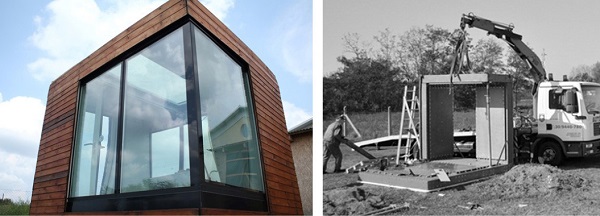
Fig. 5 shows the building completed and under construction. The WFS panels were designed as a Structure Insulated Panel (SIP) system utilising an external layer (load-bearing core and thermal insulation) and a water layer facing inwards. This was necessary because the connection of water panels required pipes that needed to remain accessible after construction. Placing these pipe connections inwards granted access to their ‘maintenance gap’ and avoided them penetrating the load-bearing structure. The building had no shading installed to ensure that there would be no interference with the results in energy performance. (The research assumed that real applications would use some kind of internal shading to avoid glare, which would improve absorption in the water layer further).
3.2 WATER HOUSE 2.0 PAVILION
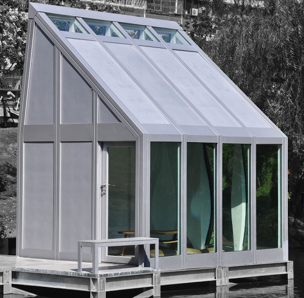
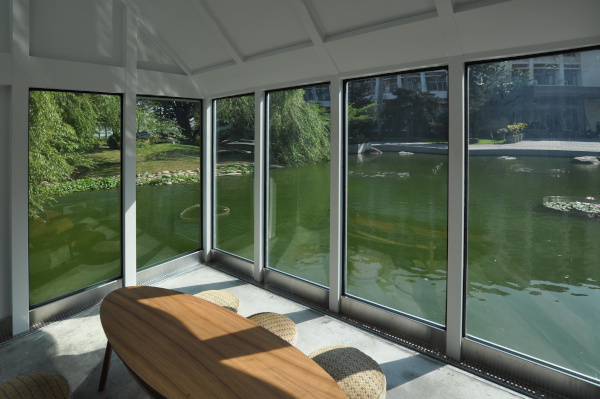
The second water house was built in Taichung, Taiwan, for a humid tropical climate. Since heating demand is minimal, the WFG panels are built with double glazing and a water layer. The WFS panels are without external insulation to maximise solar absorption. This was a major difference compared to WH01, because the whole building envelope could be used for the absorption of external heat load. Additionally, an absorption-based energy model was also more effective for the climate as the major load on cooling was a result of radiation since the temperature difference between indoor and ambient temperature is relatively low (Qahtan et al., 2014).
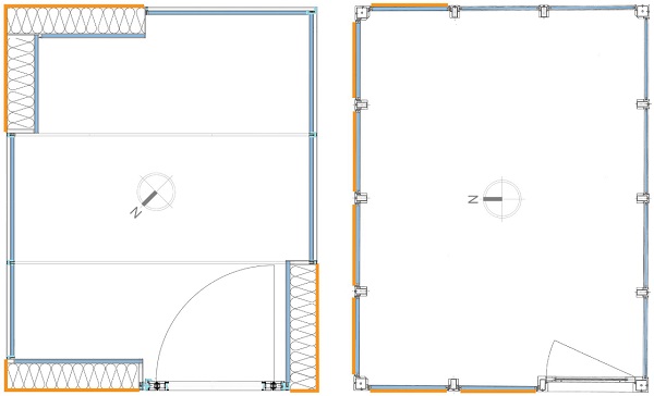
Fig. 6 shows the construction system for the building, which was a steel frame + infill panels. Similarly to WH01, the panels were connected in loops. Depending on the solar load and ambient temperature, the water flow was either automatic or enhanced with a pump. Fig. 7 shows the arrangement of the loops. The loops consisted of two walls (north and south) and floor + roof panels between.
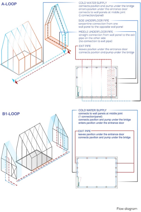
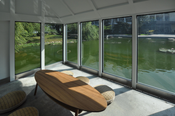
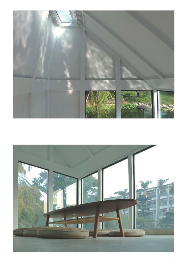
This absorption-based cooling was further enhanced by design; the north roof has no direct solar gain due to its angle and the orientation of the pavilion. Since insolation in Taichung is relatively high in any season, this geometry supported automated/pumped water flow between the two sides and provided a cooling effect as the north wall/roof radiated heat towards the outside. The south side was designed with glass panels towards the lake without shading (as shown in Fig. 8), which is not conventional for this climate. Indoor temperature was monitored, and the pump enhanced the water flow when cooling was required. The mechanical system balanced the flow with an expansion buffer in the thermal storage.
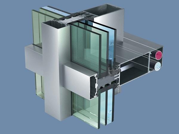
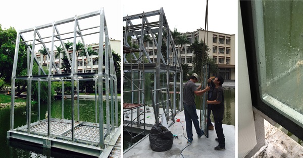
The structure of the pavilion used a curtain wall system, which consisted of structural ‘frame and infill’ WFG/WFS panels. The structural steel frame was prefabricated and assembled on site. The infill panels were installed after the frame was completed. The glass façade was fixed, and natural ventilation was through ventilation openings under the glass panels and at the top (through the ceiling).
As Fig. 9 shows, the curtain wall construction method was advantageous for assembly as it was easier to establish a gap between the panels. This was a challenge for the SIP method because the WFG panels in WH01 had to be placed on steel channels, which resulted in thermal bridging because the thickness of insulation was limited within the gap. In the case of the curtain wall system, the panels were directly attached to a structural steel frame and could be positioned more freely. This solution also proved to be more ideal in terms of loads because the structural and water layers overlapped and the panels could be supported from top and bottom as shown in Fig. 9.
4 STRUCTURAL CHALLENGES AND DESIGN ASPECTS OF CONNECTED WATER-PANEL BUILDING ENVELOPES
4.1 STRUCTURAL CHALLENGES
4.1.1 Reaction Between Water and Glass
Maintaining transparency is essential for glass because of its aesthetic and thermal characteristics. Glass corrosion and pollution can occur on both external and internal surfaces of WFG, particularly because the internal cavity is not sealed but connected to a water system.
The first liability is the possible pollution build-up on the glass surface. This could be caused internally (through polluted water) or externally (on the surface of the envelope). The former is a more important concern because the panel cannot be cleaned from the inside. Additionally, any pollution would also have an effect on the water flow, as the spacer and the valves are a potential target for contamination. This applies especially to the lower joints and spacer area where the pollution tends to gravitate during periods without water flow, which would normally occur during periods without solar gain and comfortable ambient temperature. Water infill has to be isolated and conditioned against physical or biological contamination.
Another possible issue is glass corrosion, which can be enhanced within the closed environment of the panel. Static aqueous corrosion occurs typically during fluid infill (i.e. construction) or fluid removal (i.e. repairs, partial replacements, system fallouts) because of the increased humidity within the panel. Internal glass surfaces are continuously exposed to dynamic aqueous corrosion because the glass is in constant contact with water. Alkali extraction and forming of Si-O bonds requires pH levels higher than 9.0, therefore controlling the pH level is essential.(Douglas & El-Shamy, 1967; El-Shamy, Morsi, Taki-Eldin, & Ahmed, 1975)
4.1.2 Water Pollution
Water pollution is an important aspect of the structure because of visibility and sustainability. Since ‘water house’ buildings contain a large proportion of water, it is important to consider a method of purification that can avoid water pollution and operates in a material and energy-efficient manner because low embodied energy and recyclability are essential advantages of the technology.
The most important pollutants are disease causing agents (i.e. viruses, worms, and bacteria), oxygen demanding wastes, water soluble pollutants and nutrients (that generate growth of algae and plants). Additional heat storage and piping constitute difficulties in water maintenance.
4.1.3 Water Leakage
Water leakage is a significant liability considering the hydrostatic pressure of the system, the detailing of the header with joint-valves, and the air release valves.
The static pressure of the panels results from the weight and pressure of the water infill, which is proportional to the height and width of the panels. Additional pressure comes from operation (water pump) and dynamic external loads (i.e. wind pressure). The pressure in the panels plays an important role in waterproofing because the materials for water containment cannot accommodate large expansion. Leakage therefore can be caused by the deformation of the glass.
The second important factor is the detailing of the header and the joint between the glass layers. The material of the header needs to be able to withstand the water pressure, must resist corrosion and chemical effects, provide a continuous structural surface for waterproofing, and must incorporate the valves of the panel without compromising the integrity of the enclosure. The valves of the system are an important detail for two reasons. The first issue is manufacturing because the existing glass production techniques are developed for linear and continuous panel edges. The second issue is the connection of the valves. Mullions and transoms are kept at minimum size for curtain walls and the gap between glass panes is usually between 10-40 mm. This limited space is a significant challenge for panel assembly, especially considering waterproofing and joints.
The third difficulty for water containment is the position and operation of the air release valves, because these units need to be placed at the top of the panel. This poses a challenge because the air release valves need to be operational during construction, since water infill is the last step of the assembly. Another difficulty could be the geometry of the glass planes because of the need of air removal. The main difficulty for these valves is, however, is their accessibility and small size, which would suggest a mechanical closing system instead of an automatic one.
4.1.4 Water Pressure
Estimating water pressure for fluid-glass structures is critical for safe operation and transparency. The actual pressure in the glass panel is a sum of static and dynamic loads. The former comes from the hydrostatic pressure and the latter from either external loads (i.e. wind) or internal ones (i.e. pump). Water pressure changes the load of the glass plane because it works against wind pressure and increases wind suction. Another important aspect is the weight of water. Considering the balance of heat absorption capacity and hydrostatic pressure, the ideal thickness for the water layer is between 15-20 mm (Chow & Lyu, 2017) This is about 15-20kg/sqm, which is 25 - 33% or 18 - 25% increase for double or triple glazing, respectively. This increase plays an important role in the stability of the glass, since it is advantageous against lateral forces at the cost of increasing vertical loads.
Hydrostatic pressure is also significant in terms of visibility. The maximum bending of the glass should be kept below 0.3% to avoid an impact on transparency. Considering the typical height of curtain wall applications, this is a major caveat. WFG design should reflect this limitation by either determining an ideal width-height proportion for the panels or propose geometries that have lower widths in critical areas for the same height.
4.1.5 Construction
Although WFG windows and curtain walls are similar to other glass construction methods, there are some important differences, in particular the problem of the embedded water network and the assembly process including the fluid infill.
The problem of heat bridges results from the inserted joint valves for water circulation. There are three options for positioning the valves (shown in Fig. 10):
- On the header (spacer) of the water layer
- On the internal vertical surface of glass
- On the external vertical surface of glass
Considering potential heat bridges, the following aspects had to be considered:
- high conductivity of the joints
- limitations for proper thermal insulation
- temperature difference between indoors, outdoors, and water intake
- limitations of construction, operation and maintenance
- risk of freezing (blackout periods)
- aesthetic impact
- condensation
- water flow
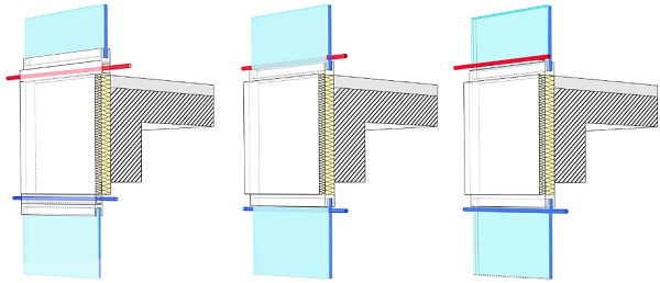
Based on these criteria, the first is the most desirable option. The most important risk factor is freezing, which can most likely occur when the water network is outside. The second concern is the energy loss of the piping network, which again makes the first option preferable. The first option also has a better aesthetic impact. Finally, it is also better for water flow as the fluid enters the glass vertically. However, this solution comes at the cost of a higher U-value, because the joints penetrate the frame.
The second factor is the size of the embedded water network. The pipes themselves can be integrated into the structure (e.g., in transoms to reach the joint valves). The difficulty is the available space for joining, which is limited to the size of the structural members, typically 40 - 80 mm.
The final challenge is the construction and maintenance, especially considering the embedded joint valves and solving the infill process (including sufficient air release during the process).
4.1.6 Insulation, Climate, Energy, and Viability
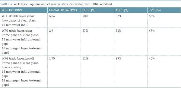
The insulation capacity of WFG and the number of glass layers depends on the climate, similar to other glass structures: WH01 and WH02 utilise triple or double layers of glass for continental and hot-humid climates. This is a logical approach considering that WFG has as wide a range of U-values compared to standard glass as shown in Table 4 and Table 5. However, WFG is also utilised as cooling-heating device and its efficiency is compromised without external insulation, which makes the triple layered WFG ideal because external insulation can keep heating/cooling performance indoors. The internal water layer is also preferable to an external one for absorption (Sierra & Hernández, 2017).Finally, a third glass layer can improve the U-value for further energy savings. Our calculations on the economic value on energy savings have shown that the system has significant energy savings that could be as high as US$3-13/m2a, which offers a competitive return-on-investment (ROI) even for the triple glazed option, especially for large buildings (Gutai & Kheybari, 2020). The third layer is also ideal because of thermal stress on glass panes, which can occur with heat absorption.
In addition to insulation, coatings, in particular Low-E coatings, play a major role in the performance of WFG. Just like in the case of insulation, climate is an important factor in considering the position and number of Low-E coatings. As presented above for WH01, climates with heating demand benefit from Low-E either on the #2 or #3 surface, which would maximise absorption for both summer and winter.
Finally, the preference for absorption or insulation should be considered for each climate scenario. WFG has a wide range for U-value (U = 2.9 – 6.34). The most important options are indicated below in Table 4. This gives the possibility to design insulation-based or absorption-based WFG panels. WFG can be tailored for specific climates, which is relevant because in tropical climates absorption has a stronger impact on energy consumption than insulation (Bui et al., 2017).
4.2 POSSIBLE SOLUTIONS AND CONSTRUCTION METHODS FOR WATER-PANEL BUILDING ENVELOPES
4.2.1 Glass Coating and Water Conditioning
The prototype tests and the buildings have shown that the risk of pollution and corrosion can be addressed effectively by controlling the chemical state of the water. Water had to be kept in a closed loop in order to maintain a stable water state. The easiest way to achieve this was to establish a closed loop of connected panels with minimum water piping that is connected to the rest of the mechanical system through a heat exchanger. In addition to the heat exchanger, the closed loop requires a pump for induced flow and a filter to capture any potential pollution in the fluid. In the case of the water houses presented here, these were placed between the pump and the panels, ideally just before the water intake valve.
Glass corrosion and degradation is usually a slow process and although L. Robinet established that the decomposition process could happen relatively quickly through the influence of pollutants (decades), this is still a long timeframe to consider it as a cause for concern. The determined period is also greater than the lifespan of glass façades (Robinet, Coupry, Eremin, & Hall, 2006). However, the formation of silica film is much faster, and it is a more important issue because of its impact on transparency. There are several ways to avoid or to slow the process. The use of Hydrolytic glass (Type I.) with high water resistance (e.g. borosilicate glass) can lower the risk of weathering. Coatings added to the glass surface could offer sufficient protection as well, like the sol-gel developed by K. Kamitani (Kamitani & Teranishi, 2003) or the water repellent glass coating by A. Matsuda (Matsuda, Matsuno, Katayama, & Tsuno, 1989)
Additionally, the physical and chemical properties of the water can affect water corrosion. R.B. Ellestad and I.I. Ostroushko established the relationship between temperature and glass corrosion (US 2 516 109, 1950; Ostroushko, Filipova, & Ignateva, 1962). R.W. Douglas assumed that the corrosion rate is independent of the pH from 1 to 9.8 (Douglas & El-Shamy, 1967) and El-Shamy pointed out that higher pH rate results increased SiO2 release rate (El-Shamy et al., 1975). Sanders et al. presented a model profile for corrosion to compare different types of binary glasses and discussed the effects of corrosion temperature on surface gel build-up (Sanders & Hench, 1973). Finally, A. Tournié et al. challenged the “gel build-up” during corrosion and pointed out the effect of base and acid attacks with boiling NaOH characterised as dissolution without structural modifications (Tournié, Ricciardi, & Colomban, 2008). Based on the research conducted, it can be established that glass corrosion can be effectively avoided if the water is kept at an ideal (room) temperature and pH level (below 9.8) to minimise weathering and pollution. This strategy also worked effectively for WH01 and WH02.
4.2.2 Water Pollution
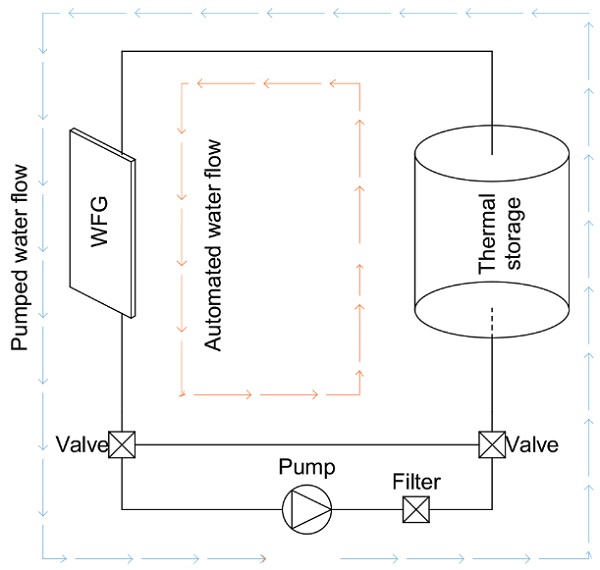
Water pollution is an important aspect due to its aesthetic impact and the potential clogging of the pipes. The thickness of the water layer in WFG is between 15 - 20 mm, which limits the joint valve and makes pollution a significant factor. Since the water is in a closed circuit, the main pollution factors are biological contamination and non-solvable pollutants. The latter can be effectively addressed by a filtering mechanism that is placed between the panel and the pump. Depending on heat load, WFG panels operate by utilising induced or automatic flow. The automatic flow is much slower and can be blocked by the filter itself, which means that the filter and the pump have to be installed parallel to the closed circuit as an alternative route that is only active when the pump is turned on, as shown in Fig. 11. Because of the need for filtering, the pump needs to be turned on regularly, even if the heat load would not require it.
The most effective solution for biological contamination is UV filtering because it presents no adverse effects on water piping, glass or waterproofing. UV is effective against all waterborne pathogens: viruses and bacteria, especially Legionella (Hijnen, Beerendonk, & Medema, 2006). Z. Liu highlighted the importance of the filter as well, which should be ideally located close to the immediate water source (Liu et al., 1995). This suggests a dispersed filter system instead of a central one (i.e. in a water tank), which was the case for Water House projects.
4.2.3 Water-Proofing and Spacer
The constant water pressure in the panel would require a dual seal solution for the panel, which is predominant for insulated glass. The advantage of this solution is that it can adapt to current manufacturing techniques and it can deal with pressure more effectively because primary sealants have low expansion capacity. The utilised material and technique for the primary sealant also depends on the spacer.
Spacers for the water layer could be tubes or frames. The former has the advantage of being easy to bend, cut, or corner keyed, which is important for containing water where a continuous structural surface is essential. However, frames have the advantage of providing a stable and flat surface for waterproofing, which is more important for fluid-glass considering the water pressure involved. Spacers can be made of steel or aluminium. The case study projects presented here are made of the latter, as glass-aluminium joints are standard in the industry and the material has the additional advantage of resisting corrosion.
The secondary sealant is critical for the integrity of the glass ceiling. Its main function is to avoid moisture ingress in the structure. For fluid-glass panels, the secondary sealant also needs to have the capacity to support the primary sealant against deformation of the glass. This requires a larger thickness than usual, which means that both primary and secondary seals are exposed to sunlight. This has both aesthetic and structural impacts because the seals may become visible and exposed to UV radiation.
4.2.4 Glass Thickness
Determining constant and dynamic lateral loads on the glass envelope is essential in order to calculate the glass thickness of the structure. The research used two sets of tests to determine two variables: the impact of hydrostatic pressure (impact of height) and water thickness (impact of water volume).
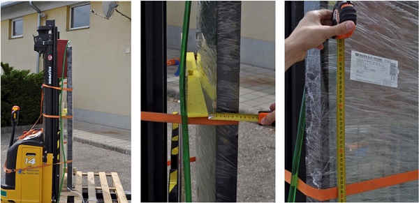
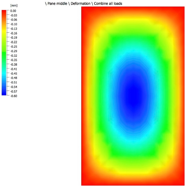
Water pressure was simulated with a load model using water weight as a uniform load, assuming a uniform pressure in the panel. This model was simulated in Glastik software, using a specific wind load that was equal to the water pressure. The results are shown in Figs. 13 - 14. The simulation was validated with prototype tests shown in Fig. 12. Laminated glass, with thicknesses of 8, 10, and 12mm, were tested. The panels used for WH02 were 820 x 1800 mm. The deformation was about 6 mm as shown in Fig. 13. This was acceptable both in terms of structure and visibility (max 0.3%).
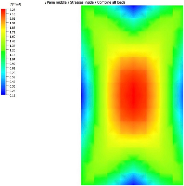
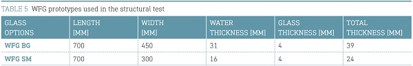
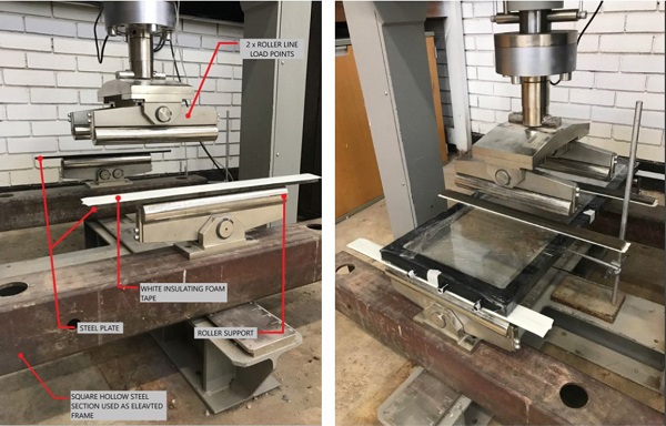
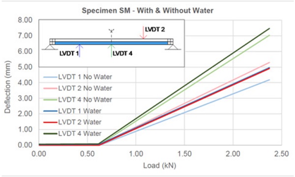
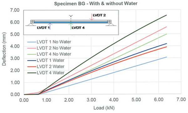
The second set of lab tests were conducted to determine the impact of water thickness. WFG was placed horizontally against vertical load in the middle of the glass plane as shown in Fig. 15. This installation had the advantage of eliminating the water pressure as a variable. Two prototypes were tested, with and without water. The panels had different water thickness as shown in Table 5. The results are shown in Fig. 15, which indicate lower deflection for the outside plane in a filled state, but higher deflection in the internal side of the panel. This suggests that the load is disseminated better in WFG by the fluid infill. Overall, the deflection rate did not show a significant increase in filled state, which suggested that neither water pressure nor infill thickness would compromise the viability of WFG critically. The load-deflection rate is much higher for BG due to its larger size and water thickness, which increases the section and strength of the spacer.
4.2.5 Construction: Frame, Detailing, Infill, Air Release
The first challenge of construction is the detailing of fluid panels because water pipes and joint valves should be embedded within the structure of the curtain wall. There are two types of pipe network: one for automatic flow and another for the pump. The latter has supply and return pipes that connect to each loop separately. These pipes can be placed in mullions and transoms or simply below/above the panel in a gap as shown on Fig. 1 and Fig. 20. This approach was used for both water house projects for WFG panels. In the case of WFS, the detail was different in order to respond to the specific climates and insulation requirements of Hungary and Taiwan. For WH01, the panels were built as a SIP system and the water layer was attached to the structural core. In the case of WH02, the opaque panels needed no insulation, and the water-steel panels had a similar thickness to the glass units. The load-bearing structure was a steel frame, which was placed between the panel units as shown in Figs. 18 and 19.
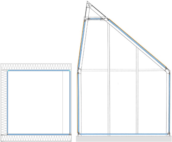
As shown on the sections (Fig. 19), from a structural perspective, the frame + infill solution is more ideal as the loads were kept along the central axis of the structural frame and the maintenance gaps between panels could be achieved easily. In the case of WH01, this was not possible because insulation was a priority and the water layer was attached on the inner side of the load bearing panels as an additional layer. This solution was not ideal from a structural perspective, but was necessary for proper insulation of the maintenance gap that provided access to the flexible joints between panels and distribution pipework that connects each loop with the main mechanical system. These gaps are visible between the panels on Fig. 1 (bottom) and Fig. 20 (top).
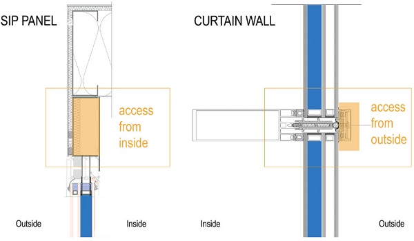
The sections on Fig. 19 and the detail on Fig. 1 also show that the SIP structural method has better thermal insulation because the steel spacer that establishes the gap between panels can be insulated from both the inside and outside, which makes the SIP options a more effective method of construction for WFG in heating dominated climates.
The second challenge of construction is the infill process and the air release from the panels. The solution for this again depends on the position of the supporting structure because fluid infill takes place when the structure is already assembled. In the case of a typical curtain wall construction, the transoms and mullions are placed behind the glass surface, which means that the air release valve can only be accessed from the outside. In the case of the SIP option, the valves can be oriented either towards the interior or exterior, as there is a gap between the glass and the roof/ceiling. Ideally, the second option is preferable, as shown in Fig. 20.
4.2.6 Energy and Climate
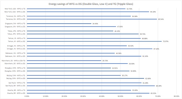
Determining the economic viability of a fluid-glass structure is essential, especially considering different climates. Based on the monitoring of WH01 and WH02 and prototype tests, a global simulation for WFG façades was conducted by the authors for 13 cities in all Köppen-Geiger climatic regions (Gutai & Kheybari, 2020). The research concluded that the system is viable in every climate region except polar climate. The research evaluated each climate, considering whether absorption or insulation should be prioritised, as this depends both on temperature and radiation. The research divided the cities into four climate groups depending on the utilised energy model: absorption-based, intermediate, hybrid, and insulation-based. The first case is when energy savings are based on absorption only (almost no heating demand).
The second is when there is heating demand, and loss in U-value increases energy consumption for heating, but the improved absorption still yields more energy savings overall. The third is when the energy balance is only positive when the solar gain is stored and reused during the heating period. The fourth group is insulation-based regions that are heating dominated areas. The simulation presented two important results: 1) WFG is viable in both hot and cold conditions and; 2) energy performance of glass buildings can be increased just by improving absorption even if it happens at the cost of higher U-value. The energy savings were between 54 - 72% compared to double glazing and 34 - 61% compared to triple glazing, depending on climate, as shown in Fig. 22.
As a developed construction system, WH01 and WH02 informed the simulation model in terms of structural layout and tested the mechanical system. In case of WH01, the building utilised thermal storage and a reversible heat pump to heat or cool the water locally and keep the temperature of the water at comfort level. Fig. 21 shows WH02, which had the same system but was mainly used for cooling.
In relation to energy consumption and climate, it should be noted that the effect of external insulation (third glass pane and an argon layer) depends on whether the water is cooled/heated or only used for absorption. In the case of the latter, 2 layers of glass with water can be sufficient. This type of water-glass has been analysed by previous research projects and was utilised for WH02. The main reason behind this solution was that the building does not need heating for most of the year due to the climate of Taichung city.
However, when heating is required, external insulation is ideal. This was the case for WH01. This improved the energy balance of the envelope and protected the water infill from freezing to a certain extent, by maintaining the indoor temperature at a higher level than the external one due to its insulation capacity.
A similar issue arose with the design of the glass coating. In the case of climates with predominant heating load, a Low-E layer can increase the absorption of the water layer. This was tested with WH01, and also justified the use of a second glass pane, which also acted as a protection for the external coating.
The properties of the WFG and standard glass used as the base case in the simulation are shown in Table 5. Overall, the system showed significant energy savings in any inhabited climate region (every climate except polar), as shown in Fig. 22.
5 CONCLUSION
The experimental buildings presented that a ‘water house’ construction system is a viable solution and the potential issues of constructing WFG envelope can be effectively addressed by the following:
- Controlling the chemical state (pH) of the water is crucial to avoid glass corrosion
- The water should be kept in a closed loop to avoid pollution.
The two buildings explored different assembly options: WH01 utilised Structure Insulated Panel (SIP) and WH02 used a frame + infill panel method. After construction, their performance was analysed and the following conclusions can be drawn:
- The SIP system offers an effective solution for external insulation. This construction method could be more applicable for colder climates where external insulation is priority (transmissive heat losses outweigh gains of absorbed radiation) because the overall U-value of the envelope is higher with the same WWR
- Utilising frame + infill method is more ideal for assembly because the panels can be positioned freely. The necessary gaps between panels can be established easily and the structural load of the water remains a central load. The disadvantage of frame + infill method is the limited potential of external insulation, especially if the thickness of the building envelope is limited, which results in a lower U-value with the same WWR.
Both construction options have merits and could be implemented in any location, however, SIP has more advantages in colder climates and frame + infill for hot climates due to their advantages/disadvantages in insulation.
Impact of WFG in construction
WFG technology is presented here with two buildings that are the first examples of connected water building envelopes. The most important difference between such hybrid envelope and solid structures is that energy can be captured and distributed within the envelope between building parts with different exposures (i.e. north and south façades or lower and higher floors). This potential is a special characteristic of this assembly method (titled ‘water house’ construction), which distinguishes WH01 and WH02 from solid buildings or other water-glass research that focuses on a single window. The significance of water house construction is:
- Energy exchange within façade brings another layer of energy-savings for a building, which does not compromise existing passive solutions but complements their performance with additional savings
- The performance of WFG in energy savings and thermal comfort gives significant freedom for architects to design glass/transparent buildings as WFG makes glass an opportunity for comfort/energy instead of being a liability (WFG provides radiant heating/cooling and energy absorption with an optically clear surface)
- WFG lowers the life-cycle impact of a building in two ways: directly (with lower energy consumption) and indirectly (with lower embodied energy by making additional structures i.e. external shadings, unnecessary). WFG presents an opportunity to calculate the primary and secondary impact of life-cycle assessment (LCA). The secondary aspect is a novel approach, which is critical for future LCA of net zero buildings, where the embodied component is higher than average.
- Energy exchange of hybrid envelopes challenge the energy models that resolve energy demands independently for each space or building. In the case of WFG, a local energy surplus is an opportunity to be distributed somewhere else or to be stored for later use.
- Energy distribution of hybrid envelopes unlock the potential creating energy-exchange links between buildings, which transform our built environment into urban micro infrastructures that collect and distribute energy. The potentials of such an approach have a significant impact on the way we design and understand buildings and cities in the future.
Suggestions for future research:
There are several important research questions suggested by the current findings. The monitoring results of the closed water loop in water houses suggest that the autonomous water flow can play a more significant role in thermal comfort and energy savings of water-house projects. This was tested with WH02. This should be determined by future research efforts. There is a need for further investigation in different options for coatings and glass panes globally with energy simulation; especially in terms of scale, WWR, and climate would help to build up effective operation scenarios for water houses, depending on the function and location of the building.
Acknowledgements
This research project was a collaboration of Loughborough, Tokyo, and Feng Chia University and was supported by the Ministry of Science and Technology in Taiwan (MOST ID 106-2218-E-035-003). The authors are grateful for the continuous support of the enterprises involved in the construction process: Jüllich Glas in Hungary and Hesung Ltd in Taiwan for their generous and continuous support.
References
Adalberth, K. (1997). Energy use during the life cycle of buildings: A method. Building and Environment, 32(4), 317–320. https://doi.org/10.1016/S0360-1323(96)00068-6
Arici, M., Karabay, H., & Kan, M. (2015). Flow and heat transfer in double, triple and quadruple pane windows. Energy and Buildings, 86, 394–402. https://doi.org/10.1016/j.enbuild.2014.10.043
Bui, V. P., Liu, H. Z., Low, Y. Y., Tang, T., Zhu, Q., Shah, K. W., ... Koh, W. S. (2017). Evaluation of building glass performance metrics for the tropical climate. Energy and Buildings, 157, 195–203. https://doi.org/10.1016/j.enbuild.2017.01.009
Chow, T.-T., Li, C., & Lin, Z. (2011a). The function of solar absorbing window as water-heating device. Building and Environment, 46(4), 955–960. https://doi.org/10.1016/j.buildenv.2010.10.027
Chow, T.-T., Li, C., & Lin, Z. (2011b). Thermal characteristics of water-flow double-pane window. International Journal of Thermal Sciences, 50(2), 140–148. https://doi.org/10.1016/j.ijthermalsci.2010.10.006
Chow, T.-T., & Lyu, Y. (2017). Numerical analysis on the advantage of using PCM heat exchanger in liquid-flow window. Applied Thermal Engineering, 125, 1218–1227. https://doi.org/10.1016/j.applthermaleng.2017.07.098
Chow, T. T., Li, C., & Lin, Z. (2010). Innovative solar windows for cooling-demand climate. Solar Energy Materials and Solar Cells, 94(2), 212–220. https://doi.org/10.1016/j.solmat.2009.09.004
Chow, T. T., & Lyu, Y. (2017). Effect of design configurations on water flow window performance. Solar Energy, 155, 354–362. https://doi.org/10.1016/j.solener.2017.06.050
Cui, Z., & Mizutani, A. (2016). Research on the reduction effect of transparent glass on cooling power energy consumption research on the reduction of cooling and heating loads by transparent solar heat absorbing glass panels (Part 2). Journal of Asian Architecture and Building Engineering, 15(3), 651–658. https://doi.org/10.3130/jaabe.15.651
DeForest, N., Shehabi, A., O’Donnell, J., Garcia, G., Greenblatt, J., Lee, E. S., ... Milliron, D. J. (2015). United States energy and CO2 savings potential from deployment of near-infrared electrochromic window glazings. Building and Environment, 89, 107–117. https://doi.org/10.1016/j.buildenv.2015.02.021
Douglas, R. W., & El-Shamy, T. M. M. (1967). Reactions of Glasses with Aqueous Solutions. Journal of the American Society, 50, 1–8.
El-Shamy, T. M., Morsi, S. E., Taki-Eldin, H. D., & Ahmed, A. A. (1975). Chemical durability of Na2OCaOSiO2 glasses in acid solutions. Journal of Non-Crystalline Solids, 19(C), 241–250. https://doi.org/10.1016/0022-3093(75)90088-5
Ellestad, L. B., & Leute, K. M. (1950). US 2 516 109. United States.
Experimental - Future Projects - 2017 | World Architecture Festival. (2017). Retrieved September 2, 2019, from https://www.worldarchitecturefestival.com/experimental-future-projects-2017
Gasparella, A., Pernigotto, G., Cappelletti, F., Romagnoni, P., & Baggio, P. (2011). Analysis and modelling of window and glazing systems energy performance for a well insulated residential building. Energy and Buildings, 4(43), 1030–1037.
Ghosh, A., Norton, B., & Duffy, A. (2016). Measured thermal performance of a combined suspended particle switchable device evacuated glazing. Applied Energy, 169, 469–480. https://doi.org/10.1016/j.apenergy.2016.02.031
Gil-Lopez, T., & Gimenez-Molina, C. (2013). Influence of double glazing with a circulating water chamber on the thermal energy savings in buildings. Energy and Buildings, 56, 56–65. https://doi.org/10.1016/j.enbuild.2012.10.008
Gutai, M. (2010). Dissolution Method and Water House Model. (Doctoral Dissertation, The University of Tokyo).
Gutai, M., & Kheybari, A. G. (2020). Energy consumption of water-filled glass (WFG) hybrid building envelope. Energy and Buildings, 218. https://doi.org/10.1016/j.enbuild.2020.110050
Gutai, M., & Kheybari, A. G. (2021). Energy consumption of hybrid smart water-filled glass (SWFG) building envelope. Energy and Buildings, 230. https://doi.org/10.1016/j.enbuild.2020.110508
Gutai, M. (2015). Trans-structures. New York: Actar Publishing.
Gutai, M. (2011). P 11 00 156. Hungary.
Gutai, M. (2012). 6250530. Japan: Japan Patent Office.
Gutai, M. (2012). EP2689192A2. European Union.
Hemaida, A., Ghosh, A., Sundaram, S., & Mallick, T. K. (2020). Evaluation of thermal performance for a smart switchable adaptive polymer dispersed liquid crystal (PDLC) glazing. Solar Energy, 195, 185–193. https://doi.org/10.1016/j.solener.2019.11.024
Hijnen, W. A. M., Beerendonk, E. F., & Medema, G. J. (2006). Inactivation credit of UV radiation for viruses, bacteria and protozoan (oo)cysts in water: A review. Water Research, 40(1), 3–22. https://doi.org/10.1016/j.watres.2005.10.030
Ismail, K. A. R., Salinas, C. T., & Henriquez, J. R. (2009). A comparative study of naturally ventilated and gas filled windows for hot climates. Energy Conversion and Management, 50(7), 1691–1703. https://doi.org/10.1016/j.enconman.2009.03.026
Kamitani, K., & Teranishi, T. (2003). Development of water-repellent glass improved water-sliding property and durability. Journal of Sol-Gel Science and Technology, 26(1–3), 823–825. https://doi.org/10.1023/A:1020747632317
Li, C., & Chow, T.-T. (2011). Water-filled double reflective window and its year-round performance. In Procedia Environmental Sciences (Vol. 11, pp. 1039–1047). https://doi.org/10.1016/j.proenv.2011.12.158
Liu, Z., Stout, J. E., Tedesco, L., Boldin, M., Hwang, C., & Yu, V. L. (1995). Efficacy of ultraviolet light in preventing Legionella coloniza-tion of a hospital water distribution system. Water Research, 29(10), 2275–2280. https://doi.org/10.1016/0043-1354(95)00048-P
Lyu, Y.-L., Chow, T.-T., & Wang, J.-L. (2018). Numerical prediction of thermal performance of liquid-flow window in different climates with anti-freeze. Energy, 157, 412–423. https://doi.org/10.1016/j.energy.2018.05.140
Matsuda, A., Matsuno, Y., Katayama, S., & Tsuno, T. (1989). Weathering resistance of glass plated coated with sol-gel derived 9TiO2 91SiO2 films. Journal of Materials Science Letters, 8, 902–904.
Moe, K. (2010). Thermally Active Surfaces in Architecture. New York: Princeton Architectural Press.
Ostroushko, Y. I., Filipova, K. ., & Ignateva, L. A. (1962). Reaction of spodumene with sulfuric acid. Russ. Journal of Inorganic Chemistry, 7(2), 126–129.
Pal, S., Roy, B., & Neogi, S. (2009). Heat transfer modelling on windows and glazing under the exposure of solar radiation. Energy and Buildings, 41(6), 654–661. https://doi.org/10.1016/j.enbuild.2009.01.003
Qahtan, A., Rao, S. P., & Keumala, N. (2014). The effectiveness of the sustainable flowing water film in improving the solar-optical properties of glazing in the tropics. Energy and Buildings, 77, 247–255. https://doi.org/10.1016/j.enbuild.2014.03.051
Ramesh, T., Prakash, R., & Shukla, K. K. (2010). Life cycle energy analysis of buildings: An overview. Energy and Buildings, 42(10), 1592–1600. https://doi.org/10.1016/j.enbuild.2010.05.007
Robinet, L., Coupry, C., Eremin, K., & Hall, C. (2006). The use of Raman spectrometry to predict the stability of historic glasses. Journal of Raman Spectroscopy, 37(7), 789–797. https://doi.org/10.1002/jrs.1540
Sanders, D. M., & Hench, L. L. (1973). Mechanisms of Glass Corrosion. Journal of the American Ceramics Society, 56(7), 373–377.
Sierra, P., & Hernández, J. A. (2017). Solar heat gain coefficient of water flow glazings. Energy and Buildings, 139, 133–145. https://doi.org/10.1016/j.enbuild.2017.01.032
Tao, Q., Jiang, F., Li, Z., & Zheng, J. (2020). A model of heat gain calculation for buildings with shuttle louvers: Verification and a case study. Journal of Building Engineering, 29. https://doi.org/10.1016/j.jobe.2019.101101
Tournié, A., Ricciardi, P., & Colomban, P. (2008). Glass corrosion mechanisms: A multiscale analysis. Solid State Ionics, 179(38), 2142–2154. https://doi.org/10.1016/j.ssi.2008.07.019