Authors: Wilfried Damen, Faidra Oikonomopoulou, Telesilla Bristogianni & Michela Turrin
Source: Glass Structures & Engineering volume 7, (2022) - https://doi.org/10.1007/s40940-022-00181-1
Abstract
Up to now, fabricating cast glass components of substantial mass and/or thickness involves a lengthy and perplex annealing process. This has limited the use of this glass manufacturing method in the built environment to simple objects up to the size of regular building bricks, which can be annealed within a few hours. For the first time, structural topological optimization (TO) is investigated as an approach to design monolithic loadbearing cast-glass elements of substantial mass and dimensions, with significantly reduced annealing times. The research is two-fold. First, a numerical exploration is performed. The potential of reducing mass while maintaining satisfactory stiffness of a structural component is done through a case-study, in which a cast-glass grid shell node is designed and optimised.
To achieve this, several design criteria in respect to glass as a material, casting as the manufacturing process and TO as a design method, are formulated and applied in the optimisation. It is concluded that a TO approach fully suited for three-dimensional glass design is as of yet not available. For this research, strain- or compliance based TO is selected for the optimization of the three-dimensional, cast glass grid shell node; in our case, we consider that a strain based TO allows for a better exploration of the thickness reduction, which, in turn, has a major influence on the annealing time of cast glass. In comparison, in a stress-based optimization, the considerably lower tensile strength of glass would become the main restrain, leaving underutilized the higher compressive strength. Furthermore, it is determined that a single, unchanging and dominant load-case is most suited for TO optimisation.
Using ANSYS Workbench, mass reductions of up to 69% compared to an initial, unoptimized geometry are achieved, reducing annealing times by an estimated 90%. Following this, the feasibility of manufacturing the resulting complex-shaped glass components is investigated though physical prototypes. Two manufacturing techniques are explored: lost-wax casting using 3D-printed wax geometries, and kiln-casting using 3D-printed disposable sand moulds. Several glass prototypes were successfully cast and annealed. From this, several conclusions are drawn regarding the applicability and limitations of TO for cast glass components and the potential of alternative manufacturing methods for making such complex-shaped glass components.
Introduction
The shaping of cast glass: possibilities and limitations
Over the last decades, glass’s perception in the engineering community has evolved from that of a brittle, fragile material used only for infill elements, to a transparent load-bearing material of a high compressive strength—stated up to 1000 MPa for float soda-lime glass by (Saint Gobain 2016; Weller et al. 2008; Ashby and Jones 2006), higher than that of even structural steel. Indeed, the structural applications of glass in the built environment are continuously increasing, yet with a considerable geometrical limitation: due to the prevalence of the float glass industry, structural glass is generally limited to the shapes and forms that can be generated by the virtually planar, two-dimensional, float panels. Cast glass can escape the design limitations imposed by the, essentially, two-dimensionality of float glass.
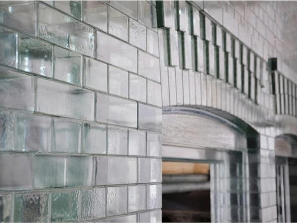
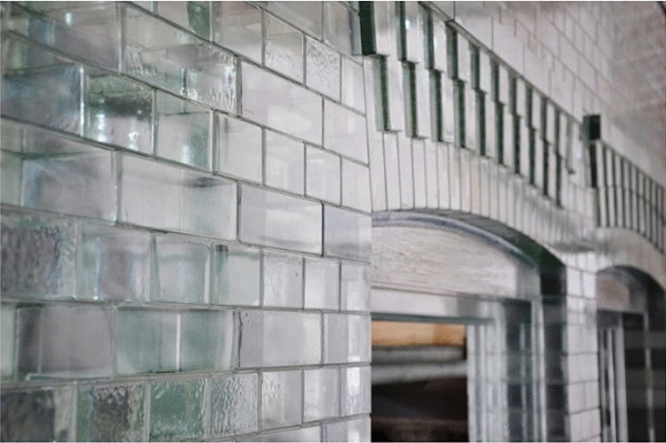
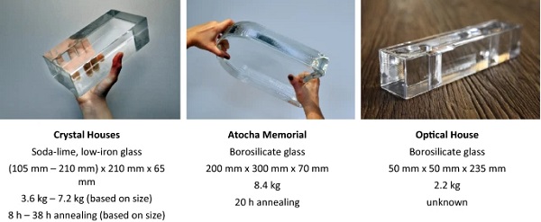
By pouring molten glass into moulds, this alternative manufacturing method allows for the creation of solid three-dimensional glass elements of virtually any shape and cross-section (Oikonomopoulou et al. 2018a). Load-bearing cast glass elements have as of yet seen little application in realized structures. Some notable examples include the Atocha Memorial (Paech and Göppert 2008), the Crown Fountain (Hannah 2009), the Optical House (Hiroshi 2013), the Crystal Houses (Oikonomopoulou et al. 2015, 2018b) (Fig. 1), the Qwalala Sculpture (Paech and Göppert 2018), the LightVault (Parascho et al. 2020) and the Qaammat Pavilion (Oikonomopoulou et al. 2022).
What is common across all aforementioned projects is that the cast glass elements follow the shape of standardized bricks, mimicking the functionality, shape and size of ceramic masonry; a glass volume which can be annealed within a reasonable time length (Fig. 2). Despite its potential for fabrication of free-form elements, little exploration has been made so far on the shapes that can be achieved in cast glass (Oikonomopoulou et al. 2018a).
A major obstacle for the manufacturing of cast glass elements of substantial mass and dimensions is the meticulous and time-consuming annealing process involved, which concerns the slow and controlled cooling of the molten glass below its softening point,1,2 (Oikonomopoulou et al. 2018a). The annealing stage is imperative in order to eliminate any possible differential strain and prevent the generation of internal residual stresses during further cooling due to uneven shrinkage (Shand and Armistead 1958), which in turn, can negatively influence the structural performance and failure mode of the resulting glass component. During the annealing stage, the magnitude of the resulting internal stresses is determined by the temperature differential between the warmest and coolest parts of the cast object.
This is directly linked to the amount of surfaces exposed to cooling, the type of glass, the amount of residual stress required and the thickness, size and mass distribution of the object involved (Shand and Armistead 1958). Accordingly, in terms of geometry, the size, mass distribution and maximum thickness of the object being cast can largely influence the required cooling times (Oikonomopoulou et al. 2018a); actually any increase in the cross-section of the object exponentially increases the required cooling time. A practical example of this can be shown by comparing two variations of soda-lime glass bricks fabricated for the Crystal Houses project (Figs. 1, 2). In this project, the smaller glass brick of 50 × 105 × 210 mm required 8 h of annealing; whereas a brick of double this width (50 × 210 × 210 mm) was found to require 36–38 h of annealing (Oikonomopoulou et al. 2015). Subsequently, in the built environment, the lengthy annealing times of cast glass manufacturing and the interconnected production costs have hampered the fabrication of cast glass elements beyond the size of regular building bricks.
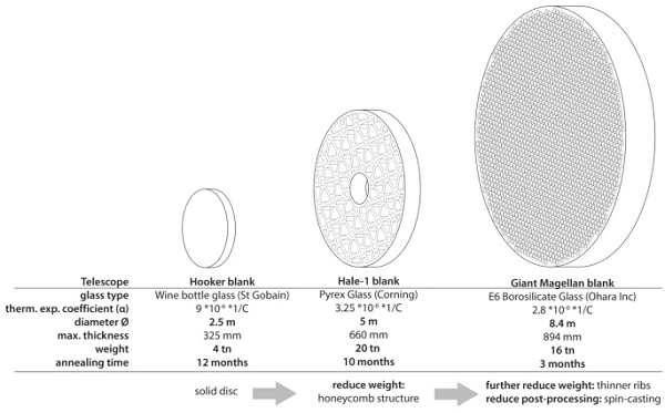
Large-scale solid cast glass elements have been nevertheless realized in non-architectural applications. The most notable ones are the monolithically cast mirror blanks of ground-based giant telescopes, which span several meters in diameter. Due to their large dimensions, annealing times are significant. As an example, 12 months of annealing were required for the solid glass mirror of the Hooker Telescope, 2.50 m in diameter and 0.32 m thick, weighing 4 tons, cast from soda-lime wine-bottle glass (Zirker 2005). To shorten annealing times, in subsequent designs, besides opting for a glass composition with a lower thermal expansion coefficient, 3 a hollow honeycomb substructure was introduced, which reduced the section thickness and mass while still ensuring a glass disk of high stiffness. Due to these changes, the more recent blanks of the Giant Magellan Telescope, despite measuring 8.4 m in diameter and weighing 16 tons each, have required an annealing time of only three months (Oikonomopoulou et al. 2018a), as shown in Fig. 3.
Topology optimization: designing structural elements of reduced mass
Towards this direction, this paper explores a novel structural design approach for designing free-form cast glass elements with reduced annealing times, through the application of structural topology optimisation.
Topological Optimization (TO) is a structural design approach which allows for the optimisation—and thus reduction—of mass in connection to structural performance. It functions by approaching the most optimal material distribution within a given design space, taking into account specified loads, supports and constraints (Bendsøe and Sigmund 2003). The reduction of mass, while maintaining high stiffness, makes it potentially promising for structural cast glass elements; through TO we can design monolithic, structural glass components of reduced thickness and volume, and thus of a reduced annealing time.
TO often results in highly-customized shapes that are complex and not always intuitive. These shapes are generally difficult and expensive to produce with traditional production techniques, such as injection moulding, milling and forming used for mass production. The use of computer-controlled additive and subtractive methods makes it possible to automate the production of such components –directly of the parts or of the respective moulds– under a high level of precision and within a reduced lead production time.4 As each element is produced individually, a high level of customisation is possible, preventing the overhead costs of tooling, but also the creation of waste due to e.g. scraps, linked to the complex shapes. By employing additive manufacturing (AM) the entire component can be made in one process (subject to the total dimensions of the printer), thus the costs related to the assembly of complex parts can also be nullified. All the above render additive manufacturing particularly attractive for limited batch productions.
On the downside, AM yields a compromised surface finishing quality that requires post-processing and still presents some limitations on the maximum product size that can be produced (subject to the size limitations of the printing bed), as well as on the materials that can be (directly) applied; whereas, the layer by layer manufacturing is still subject to standardization, which can render the use of AM challenging in applications where certification is necessary (Kawalkar et al. 2021). Regardless, AM remains the most suitable manufacturing process for realizing TO structures, in which each element is optimised according to the specific loads it has to withstand, at little additional manufacturing cost.
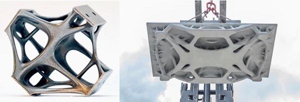
So far, practical application of TO, has remained mostly limited to high performance applications, such as aerospace design (Rozvany 2009). Various applications of TO in the built environment, realized with the aid of AM, have been investigated (Jipa et al. 2016; Prayudhi 2016; Galjaard et al. 2015; Naboni and Kunic 2019) (see Fig. 4); however, as a design tool for structural glass components it has remained rather unexplored.
Grid shells are a class of structures that show the efficient loadbearing properties of shell structures, while consisting mostly of one-dimensional beam elements, allowing for lightweight and economical structures. The complexity of the structure is concentrated in the nodes in which the beams are connected. Complex grid shell nodes designed using TO have been previously explored in steel structures (van der Linden 2015; Prayudhi 2016; Seifi et al. 2018) finding that significant weight savings can be achieved while retaining structural integrity. To the knowledge of the authors, structural grid shell nodes made of glass are a novelty.
Methodology
To investigate the potential of TO for structural cast glass applications, a glass grid shell structure has been designed, using topologically optimised cast glass for the connecting nodes.
The research process is twofold, consisting of numerical design followed by physical prototyping. For the purposes of this research, a case-study structure has been used, which is based on a pavilion built at the Singapore University of Technology and Design (Sevtsuk and Kalvo 2014). The structure has first been redesigned with loadbearing tubular glass elements in Rhinoceros 6 and parametrised using Grasshopper and the structural FEA plug-in Karamba3D. The aim is to investigate the use of TO for the design of structural cast glass grid-shell nodes that connect the tubular glass elements. The dimensioning of the glass shell structure is used to determine the dimensions and shape of the glass nodes that are to be optimised, while the FEA model provides the forces on the node, used for optimisation and structural validation.
For the optimisation, several design criteria in respect to the casting and annealing process of glass are established, derived from observations made from existing glass castings, in addition to functional criteria based on assembly and installation of the structure. These are then applied in the optimisation of the selected nodes, using strain-based optimisation in ANSYS workbench. Besides being accessible through and academic licence, this program was selected due to its extensive TO toolset, as well as its integrated modelling and FEA tools. A design loop is used, in which a base geometry is generated in Grasshopper, followed by optimisation, post-processing and FEA within ANSYS. Based on these results, the initial geometry and optimisation parameters can be tweaked as needed.
Based on the final node design, two distinct mould techniques for manufacturing such complex-shaped, customized glass elements with the aid of additive manufacturing are explored through the kiln-casting of small-scale prototypes in the Glass Lab: (i) a disposable silica-plaster mould using investment casting and a 3D-printed wax element, and (ii) a 3D-printed sand mould produced by ExOne.
Node setup and optimization goals
Case study design
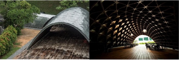
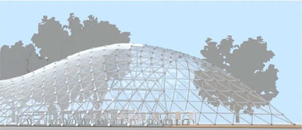
Extensive documentation of the SUTD grid shell project was provided through the SUTD (Fig. 5). This project was selected due to its freeform shape. As each of its nodes will be uniquely optimised without uniform, repeating elements, it becomes possible to realise a complex-shaped structure without great additional investments. Furthermore, the shell is designed as a compression-based structure, reducing the risk of the glass elements being subjected to significant tensile stresses—where glass presents a considerably weaker performance.
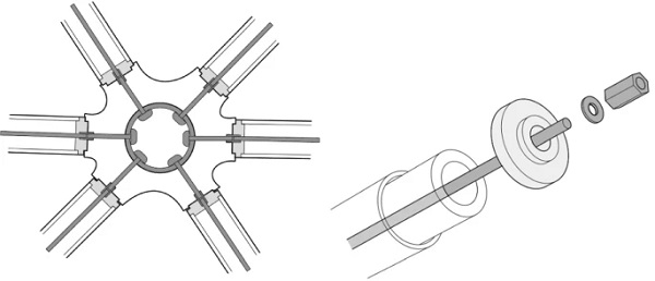
The structure of the shell has been re-designed as a hybrid steel-glass assembly. The beams of the grid consist of extruded glass tube profiles clamped between two POM plastic caps. These are held in place by a central steel rod running through the glass profile (Fig. 6). For the assembly of the structure the following principle is employed (Fig. 7): a thin steel ring is inserted into a cylindrical void at the centre of each node. Through this ring, bolts can be inserted that connect to the steel rods of the surrounding beams through a coupling nut. In this way, the glass provides stiffness to the structure and carries the compressive loads, whereas direct tensile loads are transferred by the steel substructure, making efficient use of the inherent properties of both materials.
TO as a tool for structural glass—stress vs. strain based optimisation
When using topology optimisation (TO) tools for glass, certain complications arise, as most available TO tools are designed for use in ductile materials with comparable tensile and compressive strength. Glass, however, is a brittle material, with an assumed tensile strength that is at least an order of magnitude lower than its stated compressive strength.
Two different approaches to TO tools can be distinguished: stress-based and strain based optimisation. Stress-based TO aims to minimise stress in an object for a given set of boundary conditions. Most stress-based methods simplify this calculation by using a Mises stress criteria, which is an abstraction that does not distinguish between tension and compression. This allows for a simplified and faster optimisation progress, but limits its applicability for brittle glass, where principal stresses are the cause of failure. In essence, the Von Mises criterion offers an equivalent tensile stress that is used to predict the yielding of (ductile) materials under multiaxial loading conditions.5
In comparison, principal stresses, applicable for glass design, are strongly dependent on the reference plane, which changes each time the geometry changes; making their implementation within a TO environment particularly challenging. Moreover, if applied to glass, the Mises stress criteria, results in the considerably lower tensile strength to become the limiting factor (typically considered between 30–45 MPa for annealed soda-lime glass6 and 22–32 MPa for borosilicate glass (O' Regan 2014; Granta Design Limited 2015)), leaving underutilized the considerably higher compressive strength of the material (recorded as high as 1000 MPa by (Ashby and Jones 2006), while (Oikonomopoulou et al. 2017) has conducted experiments with borosilicate glass that indicated a nominal compressive failure stress > 500 MPa).
Additionally, stress-based TO has a strong mesh dependency, with different mesh layouts and sizes resulting in different optimised geometries (Bendsøe and Sigmund 2003). Currently, TO tools suitable for brittle materials are being researched, generally focussing on concrete design, using principle stress based-optimisation (Jewett and Carstensen 2019; Chen et al. 2021) or dual material optimisation (Gaynor et al. 2013). Unlike the Von Mises-based optimisation, these methods can differentiate between the allowable values for tensile and compressive stress in the elements. However, these methods are still at an early stage of development, and due to their complexity have been limited to two-dimensional case studies.
Strain- or compliance based TO is a different approach which aims to maximise stiffness of an object. Compared to stress-based optimisation, it provides higher stiffness, while also being less dependent on the meshing. Although this approach should yield more reliable geometries, like stress-based optimization it does not offer a distinction between the allowable tensile- and compressive stress values. In addition, as stress is not directly taken into account, local peak stresses may occur. Since glass is unable to deform plastically to redistribute these local peaks, a post-analysis is essential also in this case in order to check that the resulting stresses fall within the acceptable limits.
It is concluded that both of the presented optimisation approaches have shortcomings when applied to brittle materials with a significant variation between their tensile and compressive strength values, such as glass. For the goal of this research, the TO analysis of a three-dimensional element is preferred, as this allows for a better exploration of the thickness reduction, which, in turn, has a major influence on the annealing behaviour of cast glass. Compliance-based TO analysis was chosen, as we consider it to allow for a better exploration of the thickness reduction of the brittle, cast glass component. Similarly to a stress-based optimization, strain-based optimization does also not distinguish between tension and compression, and additional analysis is required after optimisation to check for potential local peak stresses. Still, we find that in comparison, in a stress-based optimization, the considerably lower tensile strength of glass would govern as the main restraint, leaving even more underutilized the significantly higher compressive strength of the material.
Design goals for reducing annealing times
Four geometric properties have been formulated that are expected to reduce the annealing time of a solid glass object (Table 1).
Table 1 Geometric properties and topology optimization goals for accelerated annealing - Full size table
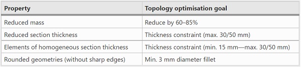
Limiting the mass reduces the overall time needed to anneal the element, by decreasing the volume of heated material that needs to be cooled. Using TO, reductions in volume between 60 and 80% compared to un-optimised geometries have been found in practice (Galjaard et al. 2015; Jipa et al. 2016).
The absence of sharp edges, and an even and thin section thickness throughout the object are essential for attaining a homogeneous cooling rate throughout the cast element (Oikonomopoulou et al. 2018a). Both sharp corners and thin sections will cool faster than the remainder of the object resulting in uneven shrinkage, thus causing undesired levels of internal stresses. Based on the suggested fillet employed at the glass blocks of the Crystal Houses project (Oikonomopoulou et al. 2018b), a minimal fillet of 3 mm radius for sharp corners is assumed. It should be noted that within TO generated geometries, sharp angles are generally not found. The optimisation process applies material in a way that minimises stress and strain, while sharply angled elements either result in stress concentrations, or contribute little to the stiffness of the object.
To create thin and homogeneous sections, a set of manufacturing thickness constraints was set in ANSYS for the optimisation process. A minimal section thickness of 15 mm has been chosen from empirical casting experience, as thinner sections could be challenging to be successfully cast, while several maximum thicknesses, between 30 and 50 mm were used. This prevents the long cooling times connected with thick sections, while also ensuring that section thicknesses remain relatively homogeneous.
Optimisation
Non-optimized component: Imposed loads and dimensions
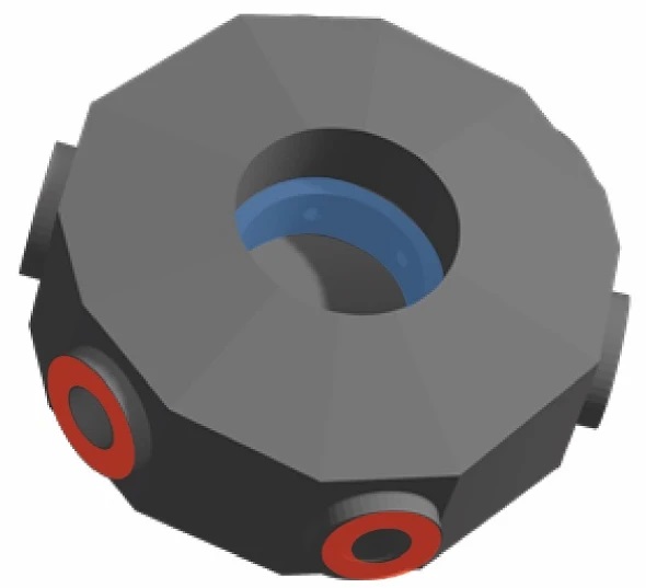
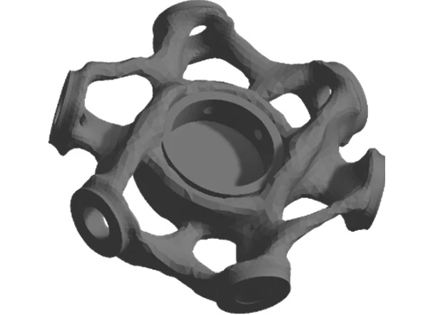
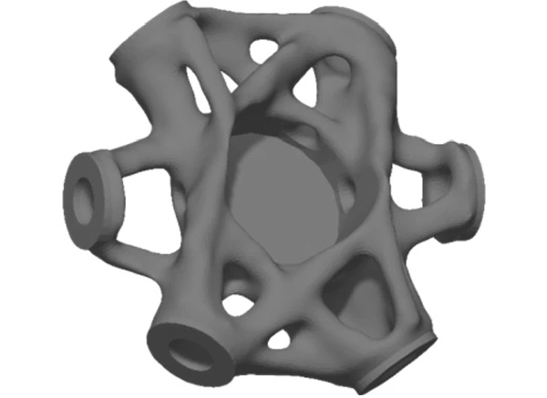
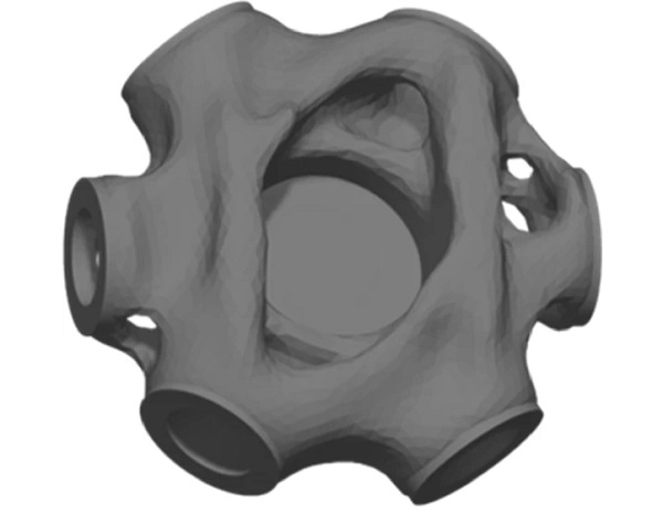
A parametric setup was made that automatically generates an un-optimised base geometry for each node, and lists the loads applied on the node. A node with a diameter of 240 mm and a thickness up to 95 mm was selected; a central void of 100 mm diameter was found to be most suitable based on assembly demands, as this is deemed the minimum size needed to insert and fasten a bolt in the central ring. Based on structural analysis in Karamba3D using the permanent load of the shell, a 0.5 kN/m2 cladding and a wind load of 0.6 kN/m2 (representative for structures under 4 m in height in a coastal Dutch situation), the glass beams of the shell were dimensioned as glass tubes with a 50 mm outer diameter and a 9 mm wall thickness. The resulting non-optimised element is shown in Fig. 8. The bending moments, shear forces and compressive normal force have been applied at outer connections where the glass beams connect to the node (red), whereas any tensile normal forces are applied at the central steel ring (blue), as these loads would not carried by the glass.
The coarse geometries after optimisation have been post-processed with Spaceclaim, the modelling software included in ANSYS. The shrink-wrap and smoothing tools were manually applied to re-mesh the found elements, which removes invalid mesh elements while ensuring a smooth surface. In addition, several elements have been re-inserted at the beam connections and central ring to ensure the node can be properly connected to the remaining structure (Fig. 9).
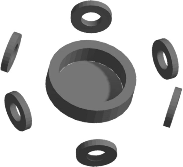
Three iterations of optimisations have been performed (Table 2), these are further elaborated on in the following chapters. Two nodes were selected for optimisation (Fig. 10), characterised by a combination of both high compressive shell forces and tensile hoop forces in the adjacent beams.
Table 2 Overview of optimization iterations for the glass node design - Full size table
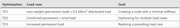
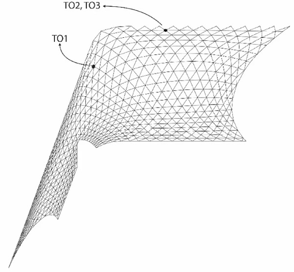
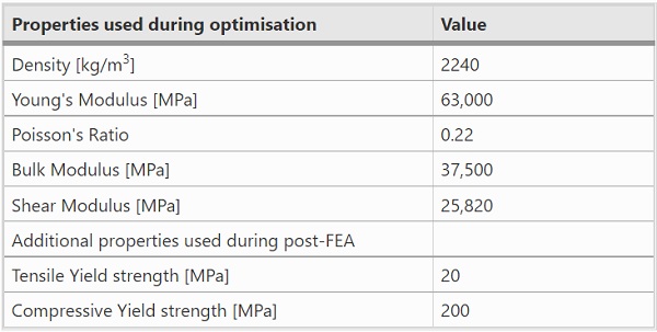
Table 3 contains the properties of the glass used for the optimisation and subsequent FEA. Borosilicate glass was chosen, due to its favourable annealing behaviour, compared to regular soda-lime glass. The strength values of glass can vary greatly, depending on the literature source used. For this research, conservative values were chosen.
Table 3 Material properties of glass used during TO and FEA - Full size table
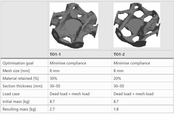
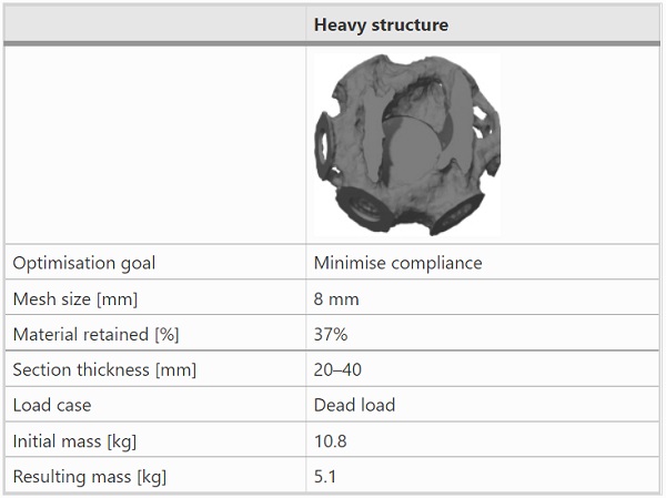
Throughout the process, the optimisation goal set was to minimise compliance, and a uniform 8 mm mesh size was used. The percentage of material retained after optimisation, and the section thickness allowed were varied in each iteration to observe their influence on the resulting geometry.
Optimization TO1, minimal stiffness through a distributed load.
The first optimisation was performed using two load cases. The fist load case applied is the permanent load of the shell structure, as this constitutes the primary dead load that the node is anticipated to carry. Optimising for this load alone bears the risk of resulting in a node design of insufficient stiffness due to over-optimisation, as the optimisation does not take any external loads into account. In (van der Linden 2015), a minimal stiffness is created by applying an additional bending moment to each beam of the node, anticipating external forces that are unaccounted for when optimising only for the dead load of the structure.
An attempt to recreate this effect was made by adding a 0.5 kN/m2 distributed out-of-plane mesh load along the entire shell, providing a guaranteed minimal load on each node. An overview of all loads can be found in Tables 9 And 10 in the appendix.
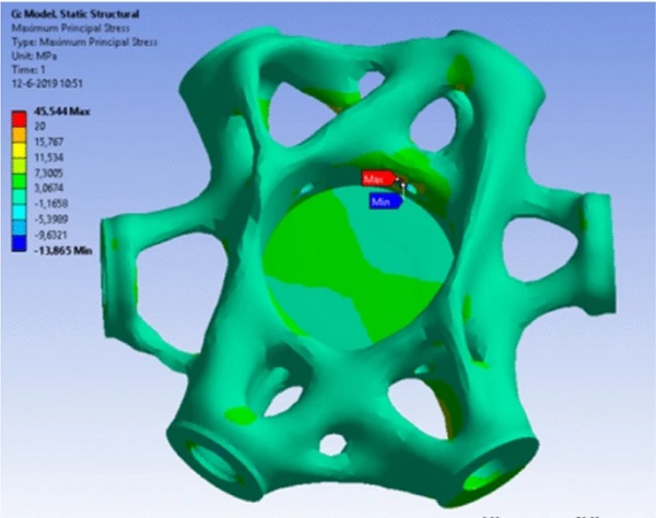
As shown in Table 4, 70% and 80% material removal have been tested. Both resulting geometries were capable of carrying the permanent load of the shell without exceeding the tensile capacity of the glass (Figs. 11, 12).
Table 4 Overview of optimisation TO1 - Full size table
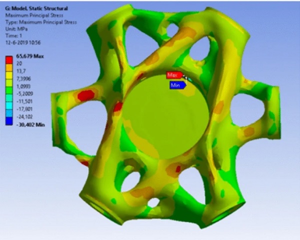
Further FEA was performed with an added 0.6 kN/m2 wind load, perpendicular to the node, with the precise forces derived from the Karamba3D model. Under this load, the tensile stresses exceed the allowable value for glass at several points (Fig. 13). This demonstrates how TO can generate weight-efficient geometries for a single, prevailing load case, but that these results become unreliable as the occurring loads start diverging from this. The pavilion chosen as a case-study is a small, relatively lightweight structure. Due to this, the stresses in the structure are greatly influenced by wind loading, making it difficult to determine a (prevailing) single load-case for the optimisation of the nodes. The attempt to achieve a minimal stiffness through a distributed mesh load proved insufficient to withstand an external load. Accordingly, optimisation TO1 was discarded, and two variations were made to investigate how these changing loads can be accounted for in the optimisation process.
Optimization TO2, two loadcases
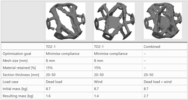
In this iteration, a methodology to optimise a node for several load-cases was explored. In this case, two separate optimisations were performed, using two distinct load-cases: the own-weight (permanent load)of the structure, and the forces on the node resulting from a 0.6 kN/m2 wind load perpendicular to the node. The setting used for both optimisations are shown in Table 5; the loads can be found in the appendix, Tables 11 And 12. The two separate optimised geometries were finally merged together to create a single geometry (Fig. 14).
Table 5 Overview of optimisation TO2 - Full size table
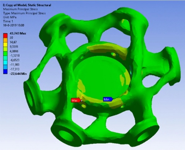
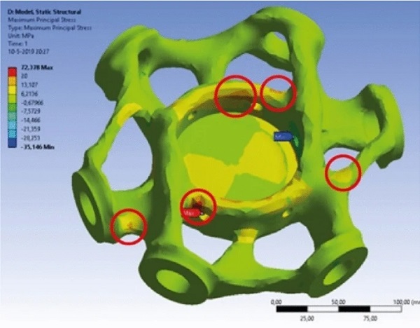
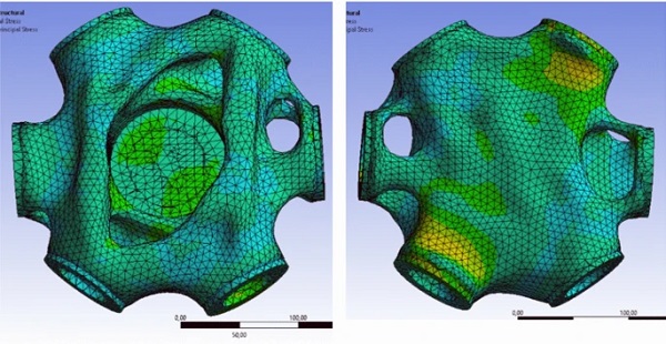
Structural analysis shows that the resulting element is capable of carrying both the dead-load and the wind load used for the two optimisations (Fig. 15). However, further analysis using a wind load in the opposite direction as the optimisation load, does cause failure at several points due to excessive tensile stresses (Fig. 16). This further demonstrates that the TO process is capable to optimise for one or more predetermined load cases, but the resulting geometries can no longer effectively carry loads that diverge from the predetermined design loads. Such an approach is particularly critical for a lightweight structure such as this, where wind loads cause large shifts in forces; compared to a heavier structure where the permanent load remains the prevailing load case.
Optimization TO3, increased dead load
Following the findings of the previous optimizations, and in order to ensure that the permanent load of the shell remains the prevailing load case under all conditions, the shell structure itself is modified to diminish the relative influence of fluctuating wind loads on the structure. The size of the pavilion has been increased by 50% in all dimensions, while the beams were increased from a 50 mm to an 80 mm diameter, and from a 9 mm to a 12 mm wall thickness.
In addition, the mass of the façade cladding has been increased from 0.5 kN/m2 to 1.2 kN/m2, representing a change from a lightweight glass covering to a double-glazed assembly. The dimensions of the node have been kept the same. The dead load of the structure was used as the only optimisation load. At the two beams where the node is subjected to tension, 3.0 kN compressive forces were applied to the glass to ensure a minimal stiffness of the node. An overview of the loads in included in Tables 13 and 14 in the Appendix, the other settings can be found in Table 6.
Table 6 Overview of optimisation TO3 - Full size table
The finalised node design is shown in Fig. 17. A linear structural analysis was performed to test the behaviour of the node under both dead-load and wind. A reduced wind load of 0.49 kN/m2 has been used, corresponding to a Dutch inland location at low heights as dictated by the Eurocode. Under various wind loads, the tensile stresses were found not to exceed the allowable value (Fig. 18).
Annealing time estimations
Determining the required annealing time for a glass object is complicated, as it is determined by a multitude of factors (Oikonomopoulou et al. 2018a). Not only the model’s shape and mass distribution, but also the amount of surface exposed to cooling, other thermal masses present in the oven, and the properties of the oven itself, all influence the annealing cycle. Though literature exists that attempts to precisely guide the annealing process, it often relies on unstated assumptions and specific circumstances that cannot be widely applied (Watson 1999).
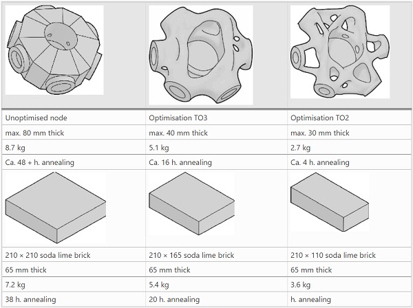
An empirical estimation of the anticipated annealing times is therefore made through comparison to existing results. Three soda-lime glass brick elements from the Crystal Houses façade project have been selected for a quantitative comparison, using the recorded cooling times indicated in (Oikonomopoulou et al. 2018b). The main aspects that determine annealing times are the glass type, mass and thickness of each element. Based on the assumption that the same soda-lime glass is used for all these elements, the following estimation can be made by comparing mass and section thickness (Table 7). Optimisation TO1 was excluded, as its geometry proved inefficient to withstand an external load.
Table 7 Annealing time estimations of the cast glass optimized node based on the annealing times prodived for the cast glass brick units of the Crystal Houses facade - Full size table
Results of numerical design
An overview of the optimization results can be found in Table 8. Using topological optimization (TO) for the design of a node that it is capable of carrying both the weight/permanent load of the shell and a variable wind load proves challenging, as a component optimised to carry the dead load of the structure becomes vulnerable for any prominent loads that diverge from it. It is possible to increase the resilience of the structure by optimising its mass distribution for a combination of prominent load cases, or by ensuring that the optimisation load case remains the dictating one under all circumstances.
Table 8 Overview of optimisation results - Full size table
Although any direct tensile loads are carried by the metal substructure, bending moments occurring due to eccentric wind-loading of the shell still result in tensile stresses. As the compliance-based TO applied in this research does not distinguish between tension and compression within the material, it can be deducted that the lower tensile strength of the glass remains normative, while its high compressive capacity remains underused.
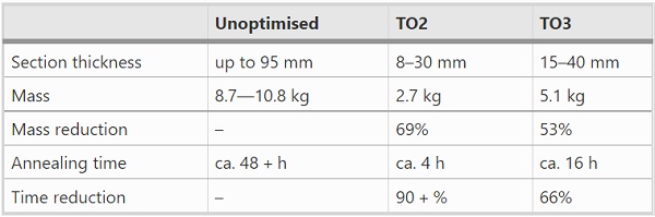
Significant weight savings were achieved despite this, finding 69% and 53% reduction for TO2 and TO3 respectively. In addition, the maximum section thickness of each component was reduced to 8–30 mm and 20–40 mm respectively from an un-optimised thickness of 95 mm. Empirical annealing times derived from comparison to the Crystal Houses project show reductions of 90% and 66%, in comparison to the corresponding un-optimised geometries.
It should be noted that the initial geometries were based on an estimation of the required volume, and should therefore be considered over-dimensioned. Indeed, in compliance TO approaches, the optimal material distribution is one of the main input variables, defined and highly dependent by the knowledge of the end user (Gebremedhen et al. 2017). The indicated mass and annealing time reductions can therefore be considered as optimistic estimates. Despite this, the results indicate that that the mass reduction achieved through TO can contribute in significantly shortening the annealing process for structural cast glass components.
Prototype manufacturing
In this research, two approaches of computer aided manufacturing are employed to fabricate with sufficient precision the complex and customized optimised glass geometries. The 3D-printing of the mould was preferred over the direct 3D-printing of the glass node as the latter still faces several important drawbacks: Although direct additive manufacturing of glass has seen some advancements (Klein 2015), it still has severe limitations in the size and shapes that can be achieved, while layering of the material and certification remain valid concerns for creating structural glass components.7 Moreover, the inability to print overhangs limits the geometries that can be produced, or requires the introduction of support material. Because of these considerations, this research focuses instead only on the use of digital manufacturing for creating glass casting moulds.
Commonly, for glass castings, either high-precision CNC-milled metal moulds or disposable, low-cost moulds are used (Fig. 19). High-precision CNC-milled moulds consisting of either steel or graphite are commonly employed in the mass fabrication of cast glass elements, as these can be reused for high-volume production (Oikonomopoulou et al. 2018a). These re-usable moulds can yield a high level of surface detailing and high dimensional accuracy; nonetheless, they generally involve high manufacturing costs, making them uneconomical for small batch productions or for single, customised components. In addition, such moulds for the casting of optimised elements of complex shape, would have to be highly intricate, consisting of multiple demountable elements to allow for demoulding; adding to both fabrication time and cost. For customized components, usually low-cost, disposable moulds are preferred. Nonetheless, these are labour-intensive and yield components of compromised accuracy and in need of post-processing (Oikonomopoulou et al.2020).
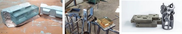
Because of these considerations, 3D-printed disposable moulds of high accuracy, are proposed here as a cost-effective solution for the casting of customized solid glass components of complex geometry. Compared to the laborious and time-consuming process of standard investment cast moulds and the high-fabrication costs of high-precision metal moulds, 3D-printed moulds are quick, easy and cost-effective to make and allow for great complexity in shapes, including undercuts and voids. In this research, two techniques of fabricating such moulds using additive manufacturing have been investigated: lost-wax investment casting using additively-manufactured wax elements, and 3d-printed sand moulds.
Lost-wax investment casting
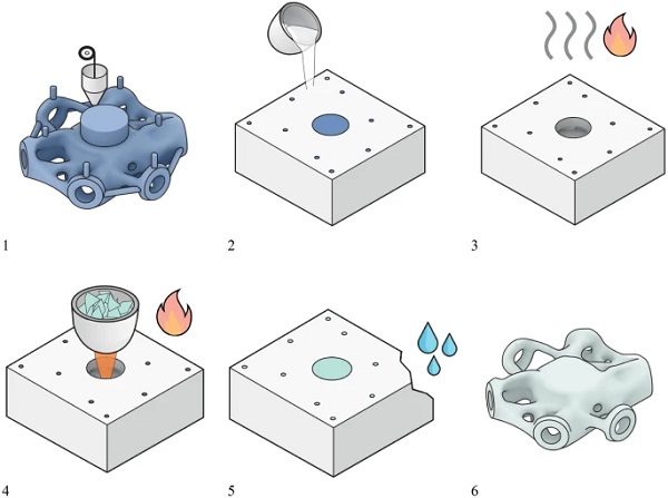
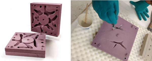
Investment casting involves the reproduction of the desired geometry in a sacrificial material; commonly wax. The production consists of several steps, illustrated in Fig. 20. A heat-resistant mould is formed around the disposable (wax) component. The sacrificial element is removed through heating in a process referred to as burn-out, or steaming, leaving a hollow mould suitable for casting.
Additive manufacturing through Fused Deposition Modelling (FDM) can be employed to fabricate the sacrificial elements. Specialised filaments have been developed for this, which burn-out at lower temperatures and leave less residue in the mould, compared to regular plastics such as PLA. For this research, P2C-175 filament was used. This is a wax-based filament developed for investment casting, available from Machineablewax.com. Using a conventional FDM printer, two optimised nodes were printed at a 1:2 scale.
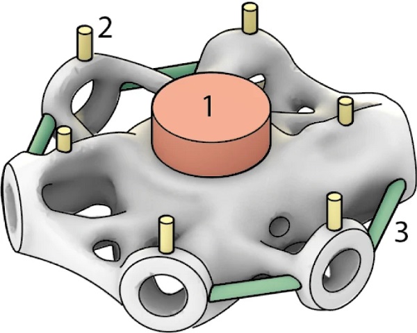
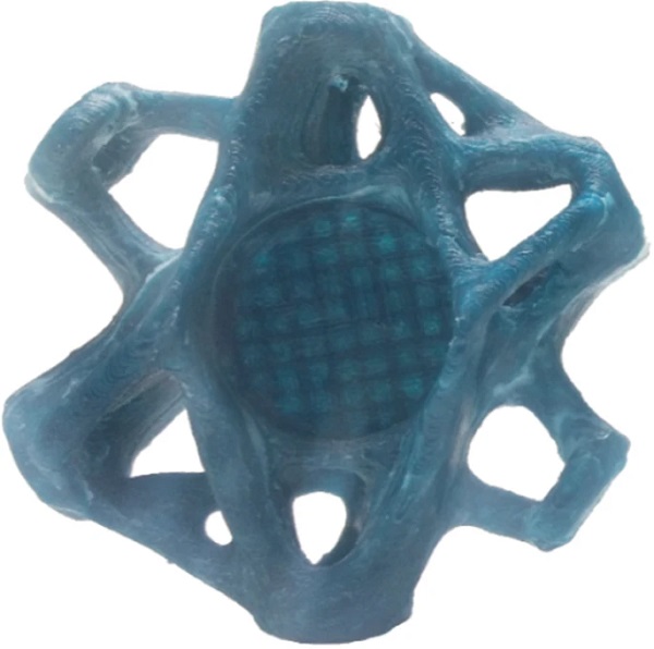
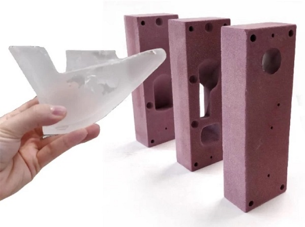
Several temporary elements were added to the wax model to improve the casting quality. These include a larger central channel for the pouring of the glass, six vertical channels to prevent air bubbles being trapped in the mould, and some additional channels to ensure a proper circulation of glass throughout the mould (Fig. 21). Around the printed wax element (Fig. 22), a silica-plaster mould was cast (Fig. 23). After solidifying, the mould has been placed in a furnace for 6 h at 515 °C to burn out the wax model.8 The final cast glass prototype can be seen in Fig. 24.
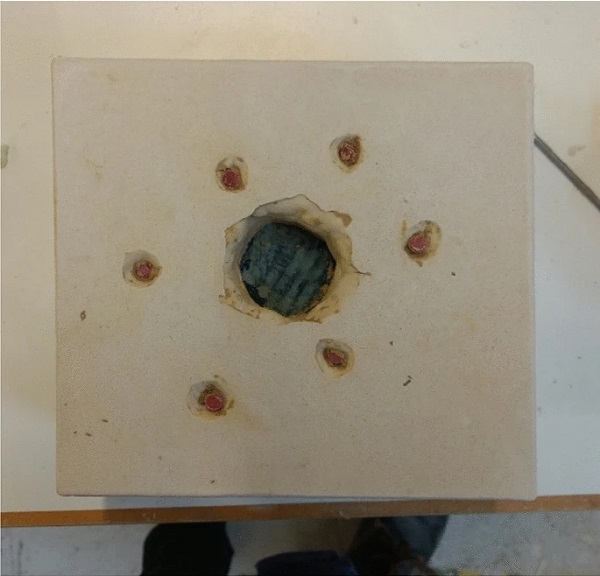
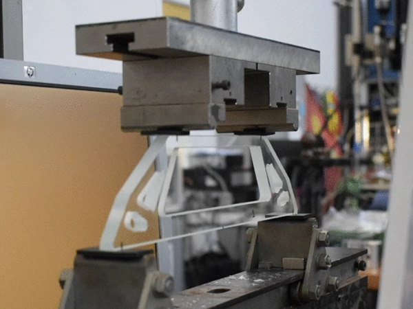
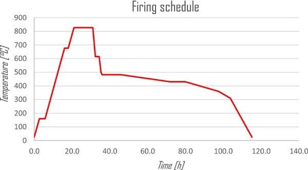
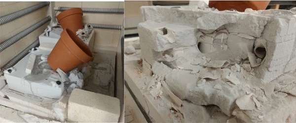
The glass has been cast using kiln-casting, as the plaster mould is unable to sustain the higher temperatures of hot-pouring. Kiln-casting is performed by placing pieces of glass in a heat-resilient reservoir (e.g. a ceramic flower pot) above the mould. Upon heating, the glass melts and flows into the mould, where it is left to anneal by controllably lowering the temperature of the kiln. This makes it possible for the object to be cast and annealed in a single furnace. However, in comparison to other glass casting methods such as hot-pouring, a longer firing schedule is necessary to ensure the glass has sufficient time to fully melt (Fig. 25). This casting was performed using recycled Schott B270 modified soda-lime glass. This glass can be cast at a lower temperature in comparison with regular soda-lime glass, with a melting temperature of 827 °C and an annealing temperature of 482 °C.
After cooling, the silica-plaster mould was softened by being placed into water, which made it easier to break and remove the mould without risking to damage the glass elements inside. In post-processing, the added air and circulation channels, and any remaining sharp edges were removed with the aid of a small handheld grinder.
Additively manufactured sand moulds
It is possible to directly manufacture moulds through 3D-printed sand, a production technique used in the metal casting industry. These moulds present a high heat resistance, and allow for highly complex shapes to be printed without additional supports. Further advantages of printed sand moulds include their fast production (normally limited to a few days), low cost, and accuracy up to 0.1 mm (based on the sand used).9
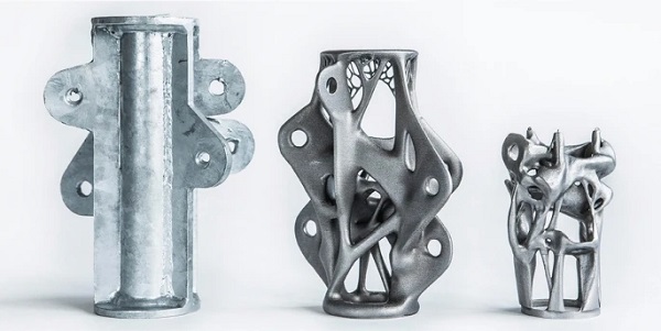
The largest element that can currently be printed using this technique is 4 m x 2 m x 1 m, using the Voxeljet printer VX4000. (Galjaard et al. 2015; Meibodi et al. 2019; Jipa et al. 2016) have applied this methodology for the casting of complex topologically optimised elements in steel, aluminium and concrete respectively (Fig. 26), while recent research on using these moulds for glass casting by (Flygt 2018; Oikonomopoulou et al. 2020) suggest that it can be used as a cost-effective, high-accuracy solution for customized cast glass objects.
Different binders are available for sand-printing. Previous experimental work by (Bhatia 2019; Oikonomopoulou et al. 2020) has indicated that inorganic binders, such as the CHP binder by ExOne, are the most suitable for the prolonged heating of the mould in the required temperatures. They also highlighted the need for the application of a coating to achieve a good finishing surface result for kiln-cast components; as the glass surface resulting from the contact with the mould is in principle, rough and translucent. Preliminary tests by (Bhatia 2019) pointed towards the application via a paintbrush of Crystal Cast (silica-plaster) for coating of the moulds—this resulted into a transparent surface, yet still rough in texture. Thus, further research in finding a coating that can yield a completely smooth texture and transparent finish surface is necessary.
Accordingly, a 3D-printed sand mould using CHP binder has been produced for the node designed in iteration TO2. The mould, printed on a 1:1 scale by ExOne, consists of 4 horizontal layers (Fig. 27), with interlocking elements to ensure that the layers remain aligned. The layered design was chosen as it simplifies the removal of left-over sand after printing, and makes the geometry more accessible for pre-processing, such as for the application of coatings. A thin layer of silica-plaster (Crystal-Cast) coating,10 was applied to prevent the fusing of the sand of the mould to the molten glass, and to ensure a smooth glass surface, reducing the post-processing needed (Bhatia 2019). This coating was selected for being easily available and affordable. A brush was used to manually apply the liquid plaster in a thin layer that does not deteriorate the printed -water soluble- sand mould.
A kiln-casting setup was used to cast the glass. Based on preliminary results of (Bhatia 2019), it was determined that for the chosen binder material, glass with a lower melting temperature is preferable. Because of this, (recycled) lead glass was selected. A similar firing schedule as before was used, with a lower melting temperature of 810 °C, and an annealing temperature of 430 °C.
The printed sand mould failed to produce a usable geometry, as upon opening the cooled furnace, it was found that the sand mould had collapsed on itself (Fig. 28). As the binder used to print the sand was less heat-resilient than assumed, it had evaporated, leaving the sand highly fragile, falling apart under the weight of the flowerpot. This appears to have happened relatively soon in the firing schedule, as little glass was found inside the mould, indicating that the mould collapsed before the glass had time to fully liquefy. The difference in behaviour in comparison to earlier tests performed by (Bhatia 2019) can be explained by the fact that the binder was exposed to high temperatures for a considerably longer period due to using a full kiln-casting process.
Due to time limitations, no further experiments could be performed on using sand printed moulds for glass casting. In further research by (Bhatia 2019), a glass element was successfully cast using a similar setup (Fig. 29). In this experiment, the ceramic container (flowerpot) containing the glass for the casting was not placed directly on top of the mould, but supported separately, preventing it from pushing down and adding additional weight on the mould. This allowed the mould to remain intact sufficiently long for glass to flow in and solidify.
Casting results
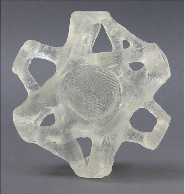
The glass elements manufactured through investment casting are found to have a rough, layered texture; an imprint of the texture generated by the FDM process used to print the sacrificial wax element (Fig. 30). A smoother element could be achieved by using a printer with a higher resolution, or post processing the element after printing to remove visible layering; though the latter could result in a loss of accuracy.
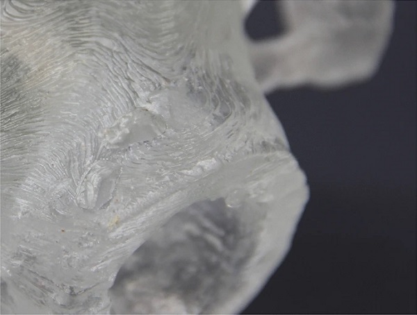
However, the resulting component also demonstrates the high level of detail that can be achieved using kiln casting. As the glass is kept above its softening point for an extended amount of time to ensure it fully liquefies, it has sufficient time to settle in the mould and transfer even the finest details of the mould texture to the glass. During the design phase, it was estimated that a 15 mm section thickness would be the smallest section that could be cast reliably. The level of detail in the 1:2 investment cast demonstrates that by using kiln casting thinner sections can be achieved, potentially further lowering the annealing time of the resulting elements.
Though the sand mould casting did not produce a valid element due to collapse of the mould, other research has yielded promising results. Further research and validation is needed to explore the potential of this methodology.
Comparing the two fabrication methods, investment casting using a wax model proved to be significantly more labour-intensive due to the multiple production steps and the additional post-processing due to the layered surface finish and supports as part of FDM printing. Although, the tools and materials required for this method are commonly available, FDM-printing at a sufficient level of precision is a slow process.
The 3D-printing of sand moulds requires more specialised tools, but allows for the direct printing of moulds of high precision. Moreover, the size of the available printers (up to 4 m x 2 m x 1 m by Voxeljet printer VX4000), makes it possible to print several elements at once, allowing for larger batch sizes and a reduced printing time per element. Labour intensity is reduced as the mould is printed directly; moreover, the printing method allows for complex shapes to be printed without supports, reducing the amount of post-processing needed. However, an amount of labour is involved in cleaning out the loose sand and applying coatings before casting in order to improve the surface quality.
Conclusions and discussion
Topology optimisation (TO) is a powerful design methodology for customized cast glass structural elements. Besides a significant reduction in material use that allows for relatively lightweight structures, in the case of structural cast glass, TO can significantly reduce the manufacturing times and the intertwined energy consumption by greatly reducing the annealing times involved. In the presented case studies, estimated annealing times were reduced by between 67 and 90%, in comparison to solid, un-optimised nodes. In practice, such a design approach, which essentially matches the glass mass distribution with the anticipated design loads, could help overcome one of the major challenges of manufacturing cast glass elements, paving the way for a much wider use of cast glass as a loadbearing material for monolithic components of substantial dimensions and intriguing design, such as transparent floor slabs, bridges or trusses.
Mass reductions of between 53 and 69% were reached, while reductions of up to 85% were initially predicted. Some reasons for the higher than expected final weight include the need to optimise for both the permanent load due to the own-weight of the structure and wind loads, resulting in additional material added in TO2 (essentially consisting of two optimised elements in one) and TO3 (the amount of removed material was lowered to increase flexibility). In addition, material was re-introduced to ensure a full connection to the connecting structural elements, further increasing weight.
The results of the casting of a scale model have showed that elements thinner than the estimated minimal thickness of 15 mm can be cast, which can be used to further reduce annealing times. However, the moulds needed for such detailed elements might become a limiting factor, considering for example the loose leftover sand that needs to be removed from the sand-printed mould.
One of the challenges encountered during the use of TO was accounting for variable (e.g. wind) loads in the design. It was demonstrated that TO is capable of designing highly optimised structures, carrying loads with only a fraction of the original material. The downside of this optimisation is a reduction in flexibility and ability of the structure to perform well under variable loads. As over-dimensioning is reduced to a minimum, structures become less able to withstand loads that are variable or are unaccounted for during design. Structures in the built environment are subjected to a wide range of loads, requiring a certain amount of rigidity and over-dimensioning to perform satisfactory under all load-cases. Thus, it should be noted that TO is not an all-encompassing structural solution. Is it sensible to use this design approach in cases where one or several dominant load-cases are present (for example when the dead-load is dominant).
Creating moulds for the casting of these complex, organically shaped and uniquely customized geometries remains challenging, relying on disposable moulds fabricated through CAM techniques such as additive manufacturing. Investment casting using an additively manufactured sacrificial prototype has demonstrated that highly intricate glass elements can be realised, though the current multi-step process is time-consuming and labour-intensive. Despite requiring further validation, 3D-printed sand moulds are believed by the authors to have the potential to greatly improve the production process of customized and perplex cast glass elements, due to their high accuracy and improved printing speed in comparison to conventional additive manufacturing methods. It should be noted here that for any project using cast glass, it is important that the manufacturing technique of the moulds is considered early in the process, as it can have significant influence on the design decisions.
Limitations of this research and further research
As no traditionally designed structural glass grid shell nodes exist, the optimised designs were compared with roughly chosen, un-optimised geometries. These initial designs can be considered over dimensioned, which means that the found total reductions in weight/mass and annealing times can be considered relatively optimistic.
The compliance-based TO process used in this research does not distinguish between tensile and compressive stresses, resulting in elements in which both are equally present. As glass is at least an order of magnitude stronger in compression than in tension, this approach does not align with the structural properties of the material. This behaviour could be improved on through the development of a TO approach for cast glass that uses principle-stress based optimisation, or dual material optimisation.
In the current methodology, the post-processing of the optimised geometry consists of a repetitive and time-consuming, manual process. If a full glass structure such as proposed in the case-study is to be realised, consisting of many cast elements, a level in automation is required to improve its feasibility. The requirements of the elements from both a structural and fabrication viewpoint can clearly be defined, while available post-processing tools, such as the ones in Spaceclaim used in this research, already operate with limited input from the user. Because of this, the authors believe an automated, parametric optimisation process is feasible.
Further testing is essential for exploring and validating the potential of 3D-printed sand moulds. The sand moulds used for this research failed during kiln casting as the selected binder was weakened by the heat of the kiln, resulting in collapse under the weight of the molten glass. Initial results by (Bhatia 2019) appear to indicate that a different binder, ExOne Anorganic, displays better resistance to high temperatures than the binder used in this research.
Additionally, the use of hot-pouring (primary) casting instead of kiln-casting should be investigated. Although at hot-pouring the glass is initially poured at a significantly higher temperature than the maximum temperature achieved during kiln-casting, due to the fact that the glass is molten in a separate furnace, the sand mould is subjected to high temperatures for a considerably shorter period of time, potentially preventing evaporation of the binder.
Besides the composition of the mould, several other parameters need to be explored further to ensure the sand moulds can be used effectively and with minimal post-processing. These include the choice of coating, and the placing and size of the inlet and circulation channels needed during the casting.
Notes
- Below its softening point the viscosity of glass is sufficient for it to retain its shape and not deform under its own weight (Shelby 2005).
- A comprehensive description of the annealing process of cast glass objects can be found at (Oikonomopoulou 2019).
- The thermal expansion coefficient of the employed glass, contributed further in reducing the annealing time. For the blank of the Hooker Telescope wine bottle glass was used (α = 9 * 10–6 1/C), whereas for the blank of the Giant Magellan Telescope, E6 Borosilicate Glass was employed (α = 2.8 * 10–6 1/C).
- the interwoven logistics with the conventional manufacturing of moulds, as well as necessary adjustments in the factory production process for the production of customized and/or complex shapes can be evaded via the use of AM. In this direction, AM can also offer a more efficient prototyping process.
- The Von Mises criterion is used to combine multiaxial stress states into a uniaxial stress that can then be compared against experimental results and uniaxial strengths, preventing the easy occurrence of matrix singularities.
- The values regarding the characteristic strength of glass can greatly vary according to the literature source used; typically a characteristic tensile strength between 30–45 MPa is mentioned for soda-lime glass.
- Based on personal correspondence with S. Galjaard, see also (Galjaard et al. 2015).
- A long burning time was chosen to ensure a full evaporation of the infill, though it is suspected by the authors that a shorter burnout time would have been sufficient.
- Based on personal communication with 3Dealize.
- Essentially, this is the same material as the mould used for the lost-wax investment casting.