Authors:
1 James Higgins, RDH Building Engineering Ltd, Vancouver, BC, Canada
2 Brian Hubbs, P.Eng, RDH Building Engineering Ltd, Vancouver, BC, Canada
3 Graham Finch, MASc, P. Eng, RDH Building Engineering Ltd, Vancouver, BC, Canada
RDH Building Science | Making Buildings Better
ABSTRACT
A desire for more thermally efficient glazing systems has led the development of new proprietary triple and even quadruple glazed insulated glazing units (IGUs) to be used in some buildings. Unfortunately, the use of some new IGU technologies has led to premature glazing failure and has resulted in the need to re-glaze buildings at significant costs to the owners of these buildings. In 2013, one such re-glazing project was completed on an all glass mixed use multi-unit residential building over a luxury hotel, which was fully occupied during the process.
The replacement work was facilitated by the planning and use of a unique re-glazing program, and the design and construction of a suspended scaffolding ring platform hung from the top of the building. This allowed the new 500 lb glazing units to be replaced from the exterior of the building with minimal disruption to the suite occupants during the work period.
The completion of the project in nine months from scaffolding erection to dismantling demonstrates the success of the re-glazing replacement plan and suspended scaffolding system, and provides good lessons for future re-glazing projects of all glass towers. Lessons learned will be relevant to glazing designers and specifiers, architects, engineers, glazing contractors and construction managers.
1. INTRODUCTION
1.1 Background
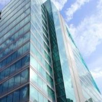
The high-rise multi-unit residential building was built in 2002 and consists of entirely silicone structurally glazed (SSG) curtain wall using R-5 proprietary triple glazed IGUs. The high-rise is a mixed-use 48 storey tower, with residential condominiums in the top 17 floors, and a hotel occupying the floors below. The top residential floors of the building incorporate a different glass low-e coating (silver) than the hotel floors (stainless steel) as a result of a late change in glazing color and properties during the construction of the building.
Fogging inside a high percentage of the IGUs was first observed in 2003, though only the clear glass on the upper floors made the fogging highly visible to the occupants. Several initial attempts were made by the contractor to fix the problem but without success. Within a few years the condensation moisture led to corrosion of the surface #2 silver low-e coating within the IGUs of the condominium floors. Our firm was retained in 2006 by the owners to investigate the IGU failure. The investigation was completed between 2006 and 2009.
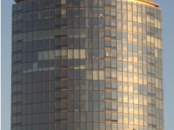
Figure 1: Widespread fogging within each IGU visible on the building elevation from the street.
Figure 2: Fogging and corrosion of the low-e coating due to condensation within the IGU.
1.2 Investigation
The comprehensive investigation of the IGU failure consisted of both qualitative and quantitative measurement in order to track and document the progression of the failure. The investigation consisted of the following procedures (Finch 2012):
- Visual review on site to rate IGUs based on fogging and low-e corrosion visible from the interior,
- Dew/frost-point testing (ASTM E-576) to measure moisture in the IGU airspace and estimate the saturation level of the desiccant,
- Laboratory desiccant saturation measurement,
- IGU pressure testing and flow testing to measure leakage rate of IGUs and flow through desiccant tubes, and
- Submersion testing of removed IGU to visually review leakage points (Figure 3)
The investigation determined that the primary failure mechanism causing fogging and low-e corrosion was a poorly designed and constructed proprietary IGU edge spacer. The edge spacer design, shown in Figure 4, used a combination of aluminium, PVC, stainless steel foil, and hotmelt butyl to create a more thermally efficient edge spacer.
However, the combination of materials and different coefficients of thermal expansion/contraction led to premature failure of the edge seal at numerous points. In addition, the replaceable desiccant tube design led to increased air and moisture flow into the IGU, which contributed to the failure.
Figure 3: Submerged IGU with airflow from discontinuities in the edge seal.
Figure 4: Proprietary thermally efficient edge spacer design.
Additional glazing issues not directly linked to the fogging and low-e corrosion were also discovered. The clear glazing on the upper residential floors of the building were found to be contributing to significant heat gain within the suites, especially in those with southern exposure. Interior ambient temperatures reached up to 110°F near the windows on sunny days.
The clear glazing and change in low-e coating during construction meant that the suite air conditioning system was too small to overcome the solar heat gain. Several IGUs were also found to have nickel sulfide inclusions in the glass lites causing spontaneous breakage. This failure is linked to poor quality control in the glass factory, where a small inclusion is embedded in the glass during the glass tempering process, and slowly expands causing eventual breakage of the glass.
The findings of the investigation and the ongoing fogging and thermal discomfort prompted the owners to seek a replacement of all the glass on the residential floors. The IGUs on the hotel floors using a darker tint and stainless steel low-e coating did not experience the same level of corrosion, and the hotel was not prepared to undergo the extensive work required.
2. INSULATED GLAZING UNIT REPLACEMENT
2.1 IGU Selection
The glass selection process began as the first step in the glazing replacement project. The initial focus was aesthetically matching the new IGU colouring with the existing hotel floors, so that the building would have a consistent glazing colour for all floors. The original IGU manufacturer no longer offers the low-e coating used on the hotel floors, so a match had to be made by trial and error.
Hundreds of samples were collected from several manufacturers in order to narrow down the selection for both the city building authorities and the building owners to choose from. Different low-e coating combinations and glass tints were used on the interior and exterior surfaces of the glass lites, in order to replicate the tint of the hotel portion of the building, as visible from the exterior.
In addition to matching the colour, the IGUs had to have an improved thermal performance over the existing clear IGUs. The solar heat gain coefficient (SHGC) had to be improved in order to reduce the heat gain and overheating issues due to the undersized air conditioning units. It was determined that the replacement IGUs must be triple glazed using all glass lites, compared to the original triple glazed using a suspended clear plastic film.
Once the IGU selection was narrowed down, several full size triple glazed mock-ups were ordered and installed on the building at the lower hotel floors (see Figure 5). This process was important to be able to view the proposed replacement IGUs directly next to the existing hotel glazing in different lighting conditions.
This step proved to be useful in further narrowing the selection, and discovering significantly mismatched colours prior to the full scale manufacturing (see Figure 6). The final colour was selected on-site from the full-scale mock-ups.
Figure 5 : Five full scale mock-ups installed at the lower hotel floors for colour comparison.
Figure 6: Significantly mismatched colour samples made visible in indirect sunlight on the building face.
In addition to the glass selection process, work was completed to ensure the most appropriate edge spacer was used. Thermally broken edge spacers using plastic thermal breaks were considered, but ruled out due to the risk of using relatively new and untested technology in IGUs in a project that has already experienced a systemic IGU failure.
As well, the triple glazed IGUs help to overcome the potential thermal degradation due to continuous metal thermal spacer. Ultimately an anodized aluminium edge spacer was used with a polyisobutylene primary seal and silicone secondary seal at each air space. Argon fill was used to further increase the thermal performance of the replacement IGUs.
Our firm visited the IGU factory on several occasions. The visits were completed to review the quality assurance/quality control procedures for the IGU manufacturing process. Several modifications had to be made to the manufacturing procedure for the custom IGUs. The large size and triple glazing required specialty made tools and assembly apparatuses.
2.2 IGU Structural Attachment
The building uses a unique aluminium frame curtain wall system, shown in Figure 7, where the IGUs are adhered to the frame using structural silicone on the offset edge of the exterior most lite. The SSG curtain wall achieves an architecturally appealing look with no extruding mullions or snap caps. The original IGU installation work was completed at the factory and the curtain wall frame was then installed on the building.
This SSG system presented a difficult challenge with respect to glazing replacement work. The curtain wall frame could not be removed from the building, so the replacement work had to be completed in the field. This work has to meet factory quality control standards and meet the same air leakage and water penetration control performance standards as the factory installed SSG system. In addition, the design of the curtain wall fame only allowed glazing replacement work from the exterior of the building. This means that the replacement work had to consist of:
- Removing existing IGUs from the curtain wall frame and discarding them
- Installing replacement IGUs in the curtain wall frame using structural silicone sealant
- Holding the replacement IGUs securely in place while the structural silicone cures
- Installing silicone sealant the joints between the IGUs for water shedding and aesthetics
The replacement work also had to be completed in a timely matter during seasons with more agreeable weather, and could not require any significant alterations or damage to the interior of the suites. These restrictions can be a challenge in the coastal climate of Vancouver, BC where the rainy season regularly falls from October to April.
Traditional SSG replacement work uses short sections of intermittent pressure plates, known as dutchies, to hold the glazing in place at the edges. Structural silicone is then installed around the dutchies. These are then removed once the silicone has cured, and the small sections without silicone are filled in.
This work requires the initial structural silicone be left in place to cure for up to 30 days in order to achieve the required structural strength to hold the glass in place so that the dutchies are no longer needed. This replacement work is often used for single broken or damaged IGUs, but presents a difficult logistical challenge when dealing with a full replacement project on multiple floors.
These challenges prompted our firm to design a replacement plan that does not require any exterior bracing to hold the IGU in place while the silicone cures, in order to avoid having to revisit the installed IGUs to complete the sealant work.
As a result, a proprietary clip rail system was designed that allowed the replacement IGUs to be secured in place from the interior and provide a structural attachment while the silicone cures. An initial design, shown in Figure 8, was completed by our firm to show the intent. The system had to both structurally secure the IGU in place, provide an air and moisture seal at the interior face of the interior lite, and allow for structural sealant application at all exterior joints.
Figure 7: Existing SSG curtain wall mullion configuration.
Figure 8: Initial conceptual clip design system.
The final design and manufacture of the clip rail system was completed by the glazing company awarded the replacement work, with the assistance of the glazing structural engineering consultant and our firm. The design uses continuous aluminium clips and a gripping cover clamp around the interior perimeter of each IGU, with an interior gasket to provide the air and moisture seal (see Figure 9).
The clip system is designed to provide a long term temporary structural attachment capable of withstanding high wind loads on the 48 storey building. This was intended to allow for the primary silicone structural attachment to be installed and fully cure before taking any loading.
Figure 9 : Continuous clip and gripping cover clamp system (red) complete with gasket (purple) adhered to the glazing with structural tape (orange).
The system uses both factory and field applied components to speed up the installation. The window installation contractor setup inside the IGU factory to install the continuous perimeter clip on each IGU prior to shipment to site.
The continuous clip on the glass was installed using pressure activated double-sided tape. The curtain wall frame clip was installed using screws into the curtain wall mullion, and the gripping cover clamp holds the clips aligned in place. The replacement work in the field using this system consisted of:
- Removing existing IGUs from the curtain wall frame (cutting existing silicone sealant)
- Cleaning mullion shoulders and attaching frame clip embedded in sealant with screws (screw heads covered with sealant)
- Inserting IGU with clips aligned to frame clips using shims
- Snapping gripping cover clamp over both clips
- Installing structural silicone sealant at the outside face of the mullion behind the offset exterior lite
The system allowed for relatively fast installation of each IGU without the need to revisit each location to remove temporary structural attachments. The clip system allowed the IGU to be installed and held in place securely, and with a complete air and moisture seal.
Proof-of-concept testing was completed at lower more accessible hotel floors prior to the full scale installation. Water testing (ASTM E1105-00(2008)) and smoke testing (ASTM E1186-03) was completed to test the interior air and water seal. Several design and installation procedure modifications were needed to achieve a consistently air and water tight clip installation. The onsite proof-of-concept testing was an integral part of the proprietary clip design process.
2.3 Work Access
The nature of the work and the design of the 48 storey high-rise building presented significant logistical problems for the IGU replacement work:
- No work was needed on the first 31 hotel floors, which are extremely sensitive to disruption and constricted views,
- Replacement work could only be completed from the exterior of the building and could only happen on one floor at a time,
- Common suspended work platforms (swing stages) were unavailable in all but calm weather and could not safely manage workers and the heavy IGUs, and
- Safely lifting large 500 pound IGUs up 48 stories on the outside of the all-glass building is extremely difficult
For these reasons, the use of a custom built suspended scaffolding ring was needed. It needed to be hung from the roof around the perimeter of the building, large enough to allow for work at one full height floor from one position, and built with the structural capacity to support two full work crews and multiple IGUs at once.
Figure 10 : Conceptual design for suspended scaffolding platform.
Figure 11: Installed suspended scaffolding and hoist towers
The full height suspended scaffolding ring platform was designed and built based on the initial conceptual idea. Eighteen hoist towers with computer controlled motors installed around the roof perimeter controlled the platform. The platform was constructed to fit closely to the building face. Flexible sheathing was placed between the platform and the building face to avoid dropping any building materials or tools.
The design and construction of the suspended scaffolding platform was completed with extensive load testing and review from third party structural engineering consultants and insurance providers. The platform also included a hoist system on a continuous rail so that IGUs once on the platform deck could be lifted and positioned in place.
The hoist motors used a specialized suction cup mechanism to attach the hoist cables to the IGUs. The platform was secured into the building structure using intermittent tie-back anchors attached into the structural concrete. The final result was a remarkably stable work platform that allowed for detailed work at all parts of the curtain wall at each floor.
One unique challenge discovered during the replacement work was that the scaffolding framing was positioned too close the building face. Foam padding was installed around each post adjacent to the building, and adjustments were made to the framing to make room for IGU replacement.
The full size IGUs measure 48 inches wide by 114 inches tall. Since lifting the IGUs on the exterior of the building was not a viable option, modifications were made to one of the two residential access elevators in order to fit the IGUs in horizontally one at a time.
A notch framed into the corner of the high speed cable driven elevator, shown in Figure 12 and Figure 13, received the top edge of the full size IGU resting on its side. The elevator experienced several breakdowns during the course of the work and required continuous monitoring and maintenance from the elevator service company. It is estimated that during the 9 months of replacement work the elevator made at least 4000 dedicated ascent/decent trips.
Figure 12 : Corner notch design in the residential elevator.
Figure 13: Completed steel notch and protection board within the elevator to protect finishes.
Custom aluminium carts were built to wheel the IGUs individually from the hotel loading bay up to the work level in the elevator. At each floor level, two suites were dedicated as the loading paths from the elevator to the work platform. Protection board and loading ramps were installed in each suite, and access to the work platform was through one open window bay on each side of the building.
2.4 IGU Replacement Work
Our firm was also the construction manager for the re-glazing project. This project management model is used where the site work involves mainly enclosure rehabilitation or replacement work. It allows the building enclosure consultant on site to have a close working relationship with the construction manager, so that field review and site testing can be more easily planned and scheduled. It also allows the construction team to have immediate access to input from the building enclosure consultant where issues arise on site.
The IGU replacement work began from within each suite to prepare the window opening. Interior finishes restricting access to the IGUs were removed before the removal took place. Small areas of wall finish were precisely removed so that the descending platform could be anchored to the structure at each floor. The platform was lowered and anchored by the scaffolding company before any work on the exterior began.
The IGUs were cut out from the exterior using speciality sealant cutting knifes. Each IGU was anchored to the hoist system and lowered onto the custom aluminium carts. The carts were then wheeled off the platform and through the designated access suite and down to the ground level through the elevator. Meanwhile, the window opening was prepared by removing the remaining existing sealant, and installing the clip rail system.
The clip installation was the most important step to achieve a correct IGU fit and interior seal. The clips had to be aligned to match with the incoming IGU clips, and receive the gripping cover clamp. The new IGUs were wheeled to the window opening and hoisted in place. Silicone pad shims were used to position the IGU, and the gripping cover clamp was snapped in place.
Figure 14 : IGU hoist motors mounted on the suspended scaffolding rail.
Figure 15: The IGU is positioned in the window opening.
Water and smoke testing was scheduled at regular intervals to verify that the installation quality remained consistent. The window opening with the designated IGU was placed under a negative pressure using a chamber and fan. Smoke (ASTM 1186-03) and water (ASTM E-1105-00 and AAMA 501.2-09) were applied to the exterior side of the IGU at the perimeter to test the integrity of the interior seal.
Testing scheduling was a challenge with the replacement work happening at a high pace, and the only form of exterior access moving away from work areas every week. Testing had to be completed quickly between the time of the initial IGU installation and the exterior sealant prior to platform descent.
Work was scheduled to replace one full floor of IGUs each week. The building has 66 curtain wall window bays, with over 100 IGUs on each floor. Suite occupants often remained out of the suite during work hours, or stayed elsewhere during the work week.
Once replacement work and final review for each floor was complete, the glass was cleaned and the platform was descended. The interior repair crew returned to each suite to repair the walls at anchoring locations and reinstate finishes.
Figure 16: Project building with one floor of IGU replacement complete
Figure 17: Project building with complete IGU replacement.
2.5 Discussion
The new IGUs on the residential floors achieved the intended results. The replacement work was completed over the 2013 summer season and the building now has new glass on the upper 17 floors that closely matches the lower existing hotel glass. The suite occupants no longer experience excessive solar heat gain, and the windows can be seen through clearly.
Initial planning, field review, and testing proved to be important steps throughout the entire project.
3. CONCLUSIONS
The selection process for the new replacement IGUs met challenges as the original manufacturer was no longer available to provide the custom glass tint. The curved face of the building meant full size glass samples had to be installed in order to view the glass in different lighting conditions.
The thermal performance of the IGU also had to be considered as the original window used a unique edge spacer design to achieve the desired thermal performance. In addition, the design of the replacement IGUs had to accommodate fast and easy installation into the existing frame, while resisting significant structural loads. This was achieved using a unique clip rail system developed and designed specifically for the project.
The suspended scaffolding was designed and built to fit closely around the face of the building and allow for replacement work at each floor and move up and down the building as needed. Finally, the construction managed project required significant attention to accommodate suite occupant’s needs, ongoing field review and testing, and an extremely tight construction schedule.
4. ACKNOWLEDGEMENTS
We would like to thank Rick Hughes, Glastech, and First Dimension Glass for their hard work to help complete the glazing replacement project. We would also like to thank Klaus Johansson for some of the on-site work photos.
5. NOMENCLATURE
IGU = Insulated Glazing Unit
SSG = Silicone Structurally Glazed
6. REFERENCES
AAMA. 2009. AAMA 501.2-09, Quality assurance and diagnostic water leakage field check of installed storefronts, curtain walls, and sloped glazing systems. Schaumburg, Illinois. American Architectural Manufacturers Association.
ASTM. 2008. ASTM Standard E1105.00(2008), Standard test method for field determination of water penetration of installed exterior windows, skylights, doors, and curtain walls, by uniform or cyclic static air pressure difference. West Conshohocken, PA. American Society for Testing and Materials International.
ASTM. 2008. ASTM Standard E576-08, Standard test method for frost/dew point of sealed insulating glass units in the vertical position. West Conshohocken, PA. American Society for Testing and Materials International.
ASTM. 2009. ASTM Standard E1186.03(2009), Standard practices for air leakage site detection in building envelopes and air barrier systems. West Conshohocken, PA. American Society for Testing and Materials International.
Finch, G. 2012. Lessons in insulating glazing unit failures. 2012 BEST3 Conference, April 2 – 4, 2012. Atlanta, Georgia.