First presented at GPD 2017
Specifically, the arch-formed bridge consists of cast, dryassembled, interlocking glass components. To validate the shape of the components, glass mock-ups in 1:2 scale have been kiln-cast and tested. This paper follows the elements’ production process from the 3D milled MDF model and the construction of disposable moulds via the lost-wax technique, to the kiln-casting at 940ºC with the “flowerpot method”.
Steps are taken towards the refinement of the production technique, with emphasis in minimizing the occurrence of air bubbles, surface flaws and internal stresses that can reduce the load-bearing capacity of the components. Polarisation techniques are employed to define the residual stress distribution of the cast elements as well as to map the consolidated flow of molten glass and the areas of inhomogeneity or noncohesion.
The structural performance of the components and their interlocking behaviour are studied by conducting shear tests on three series comprising three glass bricks with a transparent PU interlayer in-between. The fracture patterns of the specimens are analysed and correlated with the flaws and internal stresses resulting from the kilncasting process.
1. Introduction
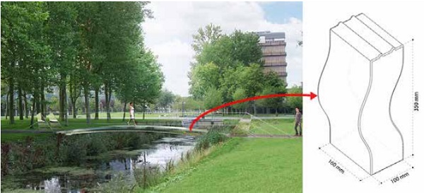
The high compressive strength of glass renders the material suitable for load-bearing applications in structures subjected to compression. In that sense, and inspired by the logic of the Roman arches, a completely transparent glass masonry bridge has been designed by Snijder et al. [1], to be located at the Green Village at TU Delft. The potential of glass masonry systems, comprising adhesively bonded solid glass bricks is well demonstrated by the completion of the Crystal Houses in Amsterdam in 2016 [2].
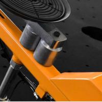
Developing this innovative glass system a step further, the bridge circumvents the need for an adhesive connection between the glass bricks. Thus it is composed of curved interlocking cast glass components, compressed together to form a stable arch (Figure 1).
In-between the glass bricks, a transparent Polyurethane (PU) rubber interlayer is placed, to avoid stress concentrations. Such dry-connections allow for the easy assembly and disassembly of the structure and favour the reuse and/or easy recycling of the individual components. These design decisions result in a more sustainable application of structural glass.
Previous research by [1], [3], [4] led to the current interlocking brick shape that limits the contact of the bricks to the upper and bottom zone of the bridge. This choice leads to a minimum generation of tensile forces in the case of asymmetrical loading. The current paper focuses on the study of the interlocking behaviour of these components.
For the purposes of the presented research, a series of glass components have been kiln-cast at the TU Delft Glass & Transparency Laboratory in scale 1:2 and tested in shear. The production of these components differs from the conventional hot-pour casting process which will be used for the final bricks for the bridge, as in kiln casting the glass is cast at a lower temperature and thus with a higher viscosity. The paper studies the production process, to determine the influence on the strength and structural behaviour of the bricks.
2. Production of the components
2.1. Mould production
Disposable investment moulds are prepared for the casting of the glass specimens. The lost-wax technique is- at this initial development stage- preferred, as it allows for the fast and low-cost production of moulds, and thus the easy experimentation with various shapes. The process consists of a series of steps (Figure 2), starting with the accurate milling of the desired brick model in mediumdensity fibre board (MDF). Based on the MDF model, a silicone counter-mould is produced that serves for the shaping of the brick model in wax.
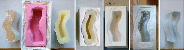
An investment slurry consisting of 1 part water to 2.8 parts Crystalcast M248- a powder mixture of Cristobalite, Quartz and Gypsum [5]- is poured around the wax and left to cure. The steaming out of the wax model results in a heat-resistant mould, suitable for glass casting up to 900ºC temperature. After the casting is completed, the mould is removed by submerging it in to water, which dissolves down the investment material. A more detailed description of the above process is described in [6].
2.2. Selected type of glass
The selected glass for the castings is B 270® i Ultra-White Glass by Schott, an optical highly transparent crown glass used for optical applications [7]. Zschimmer [8] stresses the importance of such potash-lime-silica systems -the base of crown glass- in glass technology, due to their lack of colour when compared to typical soda-lime-silica systems. The glass used is shaped in the form of lenses of 70mm diameter.
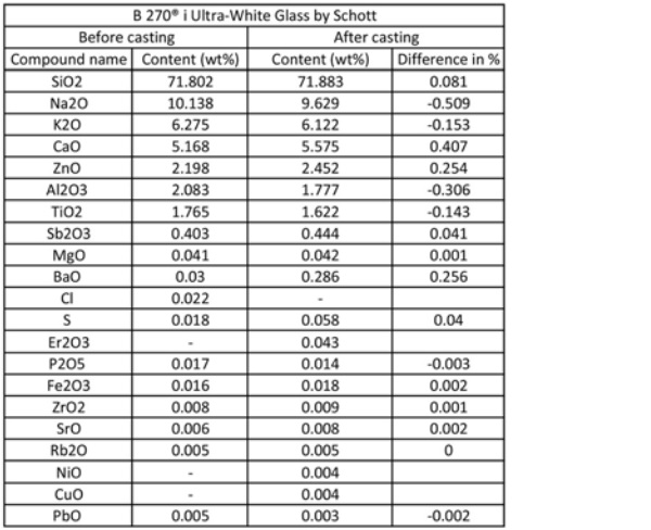
The exact glass composition is analysed with a Panalytical Axios Max WD-XRF spectrometer and the data are evaluated via SuperQ5.0i/ Omnian software. As seen in [Table 1] Zinc oxide is also included in the recipe, a compound contributing, as well, in the colourlessness of the glass [8].
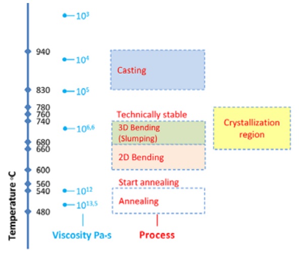
[Figure 3] provides insight to the viscosity of the glass used as a function of the temperature. In short we encounter the softening point at 724ºC, the annealing point at 541ºC and the glass’s strain point at 511ºC [9]. The forming temperature starts from 827ºC.
2.3. Casting set-up and firing schedules
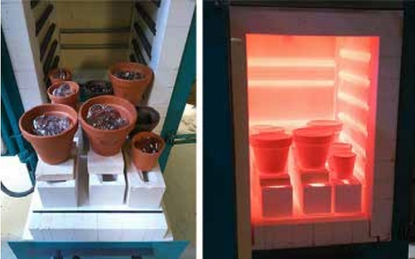
The glass bricks studied in this paper are produced by kiln-casting [Figure 4]. This production technique employs a single kiln for the melting of the glass into the moulds and for the subsequent annealing process. As the investment moulds remain in the kiln throughout the whole process, they define the maximum heating rate (50ºC/hr) and maximum temperature (900ºC) that can be reached [10].
These specifications are tested by the authors and adjusted up to a heating rate of 75ºC/hr and a maximum temperature of 950ºC. The maximum temperature reached corresponds to a glass of 10^5 dPa•s viscosity [9]. This viscosity value is considerably higher than in the hot-pour casting method, which is planned for the final production of the bricks. Indeed in such a method, viscosities of around 10^3 dPa•s or less are achieved [11], to guarantee a homogeneous and air-bubble free mixture.
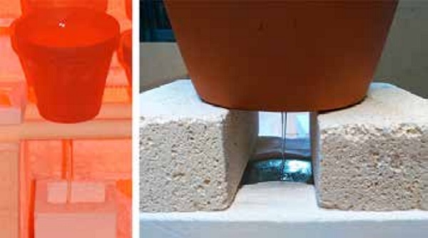
Questions are therefore raised regarding the homogeneity, cohesion and strength of the glass components produced by the kiln-casting method. The above mentioned aspects will be examined below. The “flowerpot” casting method is employed for the feeding of the glass into the moulds. This method suggests the positioning of terracotta flowerpots filled with glass above the moulds. At forming temperatures, the glass drops down through the flowerpot hole and fills the mould [Figure 5].
Four firings- Firing 10, 11, 14 and 19- are conducted for the production of the glass bricks, using a ROHDE ELS 200 S Kiln with 5-sided heating. Different variables regarding the casting set-up are presented in [Table 2].
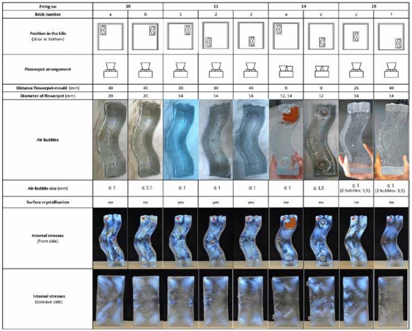
The position of the mould in the kiln, the number of used flowerpots, the distance of the flowerpots from the mould and the radius of the flowerpot hole are documented so that their influence to the final product is examined. The four firing schedules followed are presented in [Table 3].
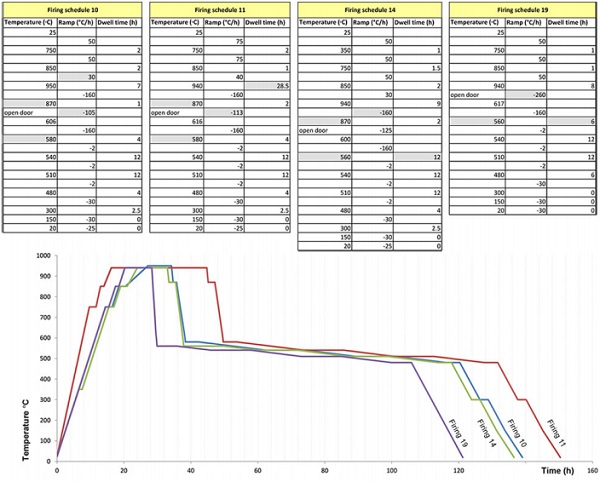
Although the schedules are mainly similar, a few alternations do occur between them. Regarding the heating up of the moulds and glass, Firing 10 has the slowest process, lasting 27hrs while Firing 11 has the fastest, lasting 16hrs. At top temperature, Firing 11 has a considerably higher dwell, reaching 28.5 hrs while the rest of the firings have a dwell between 7-9hrs.
Regarding the temperature drop from the forming temperature to the annealing point, in Firing 10, 11 and 14, this occurs in two steps, one from 940ºC to 870ºC at -160ºC/hr rate (including 1-2hrs dwell at 870ºC) and a second step at approx. -105 to 125ºC/hr rate (executed by consecutively opening and closing the kiln door). In Firing 19, the intermediate step at 870ºC is avoided, and the cooling down occurs at a -260ºC/hr rate (aided by the opening of the kiln door). Finally, in Firings 10 and 11, the annealing soak starts at 580ºC while in Firings 14 and 19 it starts lower, at 560ºC. In Firing 19, the annealing soak time is half that applied in Firing 14.
3. Assessment of the cast components
3.1. Contamination
An X-ray fluorescence (XRF) analysis is conducted with a Panalytical Axios Max WD-XRF spectrometer on a glass specimen resulting from Firing 11. The resulting composition, seen in [Table 1] is compared to the original glass recipe. The difference in content of the main compounds is not exceeding the percentage of +-0.5, therefore significant alternations in the glass recipe are not observed. Impurities due to contamination from the Crystalcast mould do appear, in percentages below 0.05, namely Nickel Oxide (NiO=0.004%), and Copper Oxide (CuO=0.004%).
The content of Barium Oxide (BaO) and Sulfur (S) is also increased due to contamination from the mould. Especially interesting is the presence of Erbium Oxide (Er2O3=0.043%) after casting. This is an expensive element often used in soda-lime silicate glasses as a luminescent dopant or to create optical amplifiers [12], [13]. Since optical glass lenses are used for melting, it is possible that Erbium traces exist in the original recipe and were not traced in the XRF test. An XRF analysis of the Crystalcast is required to define which of the above impurities are indeed attributed to the investment material.
3.2. Air-bubble entrapment
In [Table 2] the distribution and sizing of the entrapped air is seen. It can be observed that the most influential parameters for the size and spreading of the air-bubbles is the size of the flowerpot hole and its distance from the mould. The least air-content is seen in Firing 14, where the minimum flowerpot hole diameter and distance from the mould is found. This can be explained if we focus on the melting and pouring process, as this occurs from the flowerpot to the mould [Figure 6].
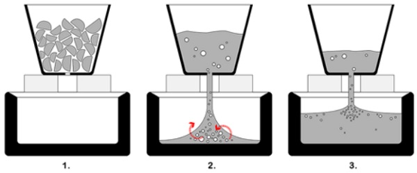
First, the glass starts to melt from the boundaries of the flowerpot towards its interior. As the lenses start to fuse together, big bubbles are formed due to the initial existing voids from the stacking of the lenses. Then, the molten glass- with the big bubbles present- starts to flow down the mould and mix with the existing air, creating a new series of big bubbles. The more the level of the molten glass rises in the mould, the less the impact the glass has when dropping and thus the smaller the created air-bubbles.
Considering the above, the reduction of the path to be travelled by the molten glass stream (flowerpot closer to the mould) creates less turbulence and thus less air-bubbles. This is also the case with a smaller stream diameter (smaller flowerpot hole). Moreover, a small flowerpot hole prevents the big bubbles formed in the flowerpot to pass through together with the glass.
In Firing 14, the use of two smaller flowerpots instead of one bigger further contributes, as less voids occur while stacking the glass lenses inside the smaller pots. The increase of the dwell time at top temperature seems to be less decisive than the above variables in the content of air. This is observed in the samples of Firing 11 -kept at top temperature for approx. 20hrs more than the other samples- that still have a high content of air-bubbles.
In Firing 19- the only firing that has one abrupt cooling stage directly from 940ºC to 617ºC at -260ºC/hr rate- an intense swirling of miniature air-bubbles is seen. It should be noted that this firing schedule also has the fastest heating rate from the start of the forming temperature towards the top temperature. This fast heating implies that the glass is dropping in a faster rate and while larger differentiations in the temperature of the melt occur.
This is expected to intensify the swirling of the molten glass inside the mould. Moreover, the fast cooling abruptly “freezes” the air-bubbles in place. At the top surface of both bricks, two bubbles of larger diameter were about to escape when they got trapped in the glass by the abrupt cooling.
This shows that similar bigger bubbles (caused at the initial melting step) that existed in the samples of the other firings had enough time to escape with a slower cooling rate. In principle, such bubbles have a bigger volume that creates a bigger upward force, making their escape easier than in the case of the smaller bubbles (that even after 28.5hrs at 940ºC in Firing 11, they were still present). Finally, the position of the moulds in the kiln has negligible influence in the formation of air-bubbles.
3.3. Surface crystallization
Crystallization at the top surface is only observed in the samples of Firing 11. This crystallization appears in the perimeter of the bricks, where the glass surface is in contact with the mould. The nucleation is thus linked to the mould material and possibly to the contamination of the air circulating inside the kiln.
Although the dangerous crystallization zone of B 270 glass is empirically located between 780-660ºC, the prolonged presence of the samples at top temperature and the extra hour of dwell at 870ºC seems to affect the growth from the nuclei. As the temperature range of crystallisation can differ with the nucleating agent [14] an analysis of the percentage of crystallinity should be conducted in order to identify the present crystal.
3.4. Internal stresses
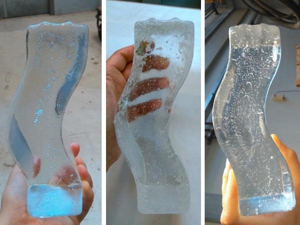
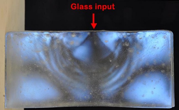
A qualitative estimation of the strain concentration and the uniform stress regions is made by projecting a polarized white light source behind the bricks and photographing them with a crossed circular polarized filter. Areas subjected to stress exhibit optical birefringence, causing the polarized light beam to exert the glass object with a phase difference that corresponds to the presence of isochromatic fringes [15].
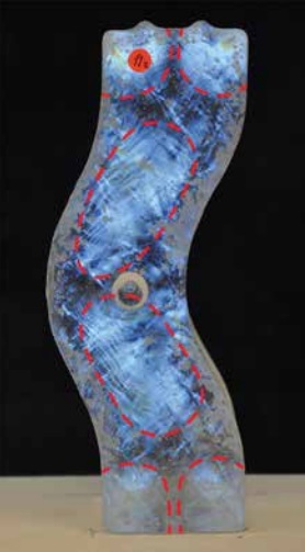
In [Table 2] the results of the polarized pictures can be seen and compared. In general, regardless the firing schedule, the location of the moulds in the kiln, and the number of flowerpots used, all bricks seem to have the same stress distribution [Figure 7].
The geometry of the brick is thus catalytic in the arrangement of these stress regions. The polarized images suggest that these regions are linked with the manner the molten glass is flowing from the flowerpot stream inside the specific shape of the mould. This is especially evident when studying the polarized images of the concave side of the bricks [Figure 8].
The regions imply that the flowing glass mass - due to its relatively high viscosity at the top temperature- does not entirely cohere throughout the total volume, resulting thus to the occasional appearance of fusion lines/strips. The described layering is particularly evident in the bricks of Firing 19 that are abruptly cooled to the annealing point. Regarding the quantity of the stresses, the bricks of Firing 10, as well as the bricks 11-1 and 19c have higher internal stresses.
Other factors -for example the location of the moulds in the kiln and therefore their proximity to the kiln-door, the heating elements or other moulds- seem to interfere with the cooling schedule of the bricks, causing the observed irregularities. The samples presented in this paper are not sufficient for drawing conclusions on the exact effect of these factors.
4. Experimental validation
4.1. Experimental set up
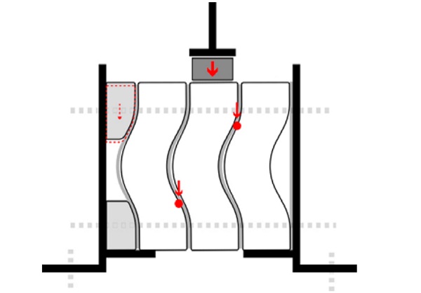
The bricks with the least internal stresses, layering and air-bubbles are chosen for the shear experiment. Regarding the experimental set up, three glass bricks with a 2mm thick PU rubber sheet of hardness 70A in between, are framed by two steel L-shaped frames [Figure 9].
The frames are fixed on the base of a Zwick Z100 displacement controlled universal testing machine. Two extra steel plates welded at the frames prevent the side bricks from moving downwards. In between the compression head and the middle brick, an aluminium profile is placed that fits the dimensions of the brick. Loose acrylic parts shaped to match the brick’s geometry are placed on the one side for support.
The L frames are bolted together until the bricks are fixed in place. Between the horizontal surfaces of the glass components and the elements of the setup, 2mm thick sheets of neoprene are placed. Three shear tests are conducted until failure, with a displacement speed of 10mm/min. The bricks are lit with white polarized light and photographed during the experiment with a crossed circular polarisation filter.
4.2. Results
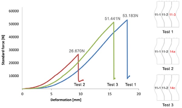
In [Figure 10] the load is plotted versus the displacement. Since the contact area between the bricks is limited to their upper and lower part, two point loads develop at the side bricks [Figure 9] during the loading of the middle brick.
All tests terminate with the failure of the brick on the right that is confined between the middle glass brick and the L-shaped frame. The loose acrylic parts in contact with the brick on the right allow, in fact, for minor adjustments in the position of this brick and therefore the development of a more favourable load case. The point load acting on the right brick subjects it to bending, creating a zone of tension at its concave surface, from where eventually all bricks start to crack.
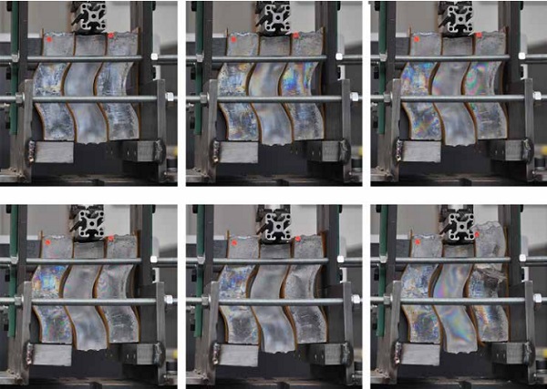
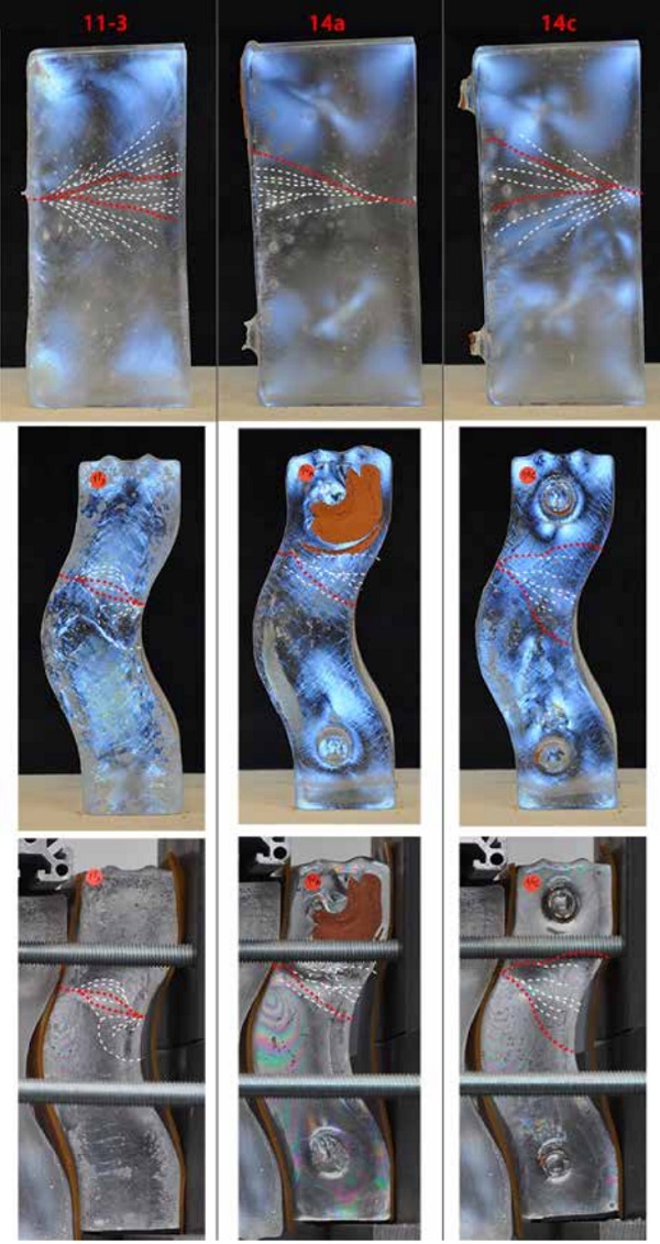
In [Figure 11], the gradual increase of the number of isochromatic fringes in proportion to the increase of the external loading can be seen [16]. In [Figures 12] the correlation between the areas where the isochromatic fringes appear during the experiments and the fracture zone of the bricks is seen. In addition, the fracture patterns are linked with the initial polarized images of the bricks, to determine possible defects that could affect the crack path.
It is observed that within the weakest zone dictated by the load case, possible flaws found in the glass from the casting become the origins of fracture. This is particularly evident in Test 2/ Brick 14a, where the crack originates from an impurity cluster combined with an air-bubble. Such clusters are not directly observed in the other two cracked bricks (11-3, 14c) which could explain why these bricks failed at double the load. Regarding the path of the cracks, they tend to follow fusion lines and internal stress regions found in the initial polarized images.
In brick 11-3 (side view) for example, the crack spread corresponds to a cone region formed exactly below the flowerpot. In the case of brick 14a, when removing the initially attached flowerpot, a damaged glass zone around the terracotta traces was created, which acts as an attraction to the crack path.
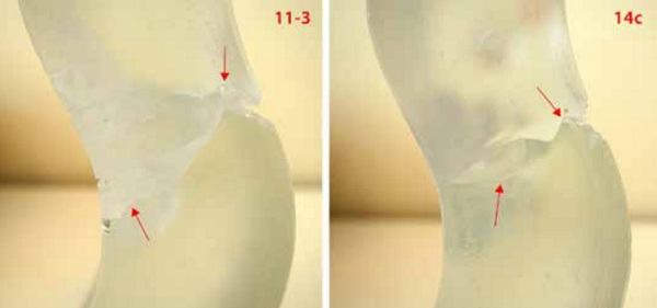
In [Figures 13] a wave is seen at the crack travelling through brick 11-3 and 14c. Such local deviations can be caused by internal stresses or inhomogeneities [17]. Areas of lower fracture toughness could occur due to the kiln-casting process, introducing weaker zones that divert the crack. An indentation test should be conducted to define possible differences in the fracture toughness along the glass mass.
5. Conclusions
In this paper, interlocking kiln-cast glass components are produced and tested, to define their structural performance. The analysis of the kiln-casting method and its results highlights the influential factors on the quality of the glass components. The process can be optimized when a slower heating rate is adopted, in combination with the use of smaller flowerpots placed directly above the moulds.
This is crucial, as flaws generated during the casting stage can initiate failure when subjected to tension. The polarized images of the bricks indicate zones of fusion and inhomogeneity in the glass, due to casting at a relatively high viscosity. Upon brick failure, these are considered weak zones that attract the path of the crack. The kiln-cast bricks -produced for the first experimental phaseform therefore the worst case scenario, as the final hot-poured bricks are not expected to contain these flaws in such extent.
Nonetheless, the governing factor in the failure mode of the bricks is the applied load case. In that sense, questions arise whether the partial contact of the bricks at their bottom and top surface- which introduces point loads- is desired. The redesign of the bricks so they achieve full contact along their height could enhance the structural performance of the system and should be experimentally validated in the next research phase.
References
[1]. Snijder, A., Smits, J., Bristogianni, T. & Nijsse, R., Design and Engineering of a Dry Assembled Glass Block Pedestrian Bridge in Challenging Glass 5, B.L. Belis, Editor. 2016: Ghent.
[2]. Oikonomopoulou, F., Bristogianni, T., Veer, F., and Nijsse, R., The construction of the Crystal Houses façade: challenges and innovations. Glass Structures & Engineering, 2017: p. 1-22.
[3]. Sombroek, I., Structural cast glass; A research process of design and experiment towards a feasible geometry for a cast glass element, in Architecture and The Built Environment. 2016, TU Delft.
[4]. Aurik, M., Structural Aspects of an Arched Glass Masonry Bridge, in Civil Engineering and Geosciences 2017, TU Delft.
[5]. SRS. MSDS Glass Investment Powder. 2003; Available from: http://artisanfoundry.co.uk/product_info.php?products_id=131.
[6]. Bristogianni, T., Oikonomopoulou, F. Veer, F. A. & Nijsse, R,. Design and production of a structural cast glass element for a transparent dome. in Proceedings of the 6th International Conference on Structural Engineering, Mechanics and Computation, SEMC 2016. 2016. Cape Town, South Africa: CRC Press.
[7]. SCHOTT. B 270® i Ultra White Glass. 2013; Available from: http://www.schott.com/advanced_optics/english/products/optical-materials/thin-glass/ultra-white-glass-b-270-i/index.html.
[8]. Zschimmer, E., Chemical Technolodgy of Glass, ed. M. Cable. 2013, Sheffield, UK: Society of Glass Technolodgy.
[9]. KNIGHT, OPTICAL. Technical / Sheet Glasses TSG-B270. Available from: http://www.knightoptical.com/technical-library/sheet-and-technical-glasses/.
[10]. Gold, Star. Gold Star Powders. Available from: www.siamcasting.com/download/SCP.pdf.
[11]. SCHOTT, Technical Glasses, Physical and Technical Properties. 2014: Germany.
[12]. Krsmanović, R., Bertoni, G. & Van Tendeloo, G. Structural Characterization of Erbium doped LAS Glass Ceramic Obtained by Glass Melting Technique. in Eighth Yogoslav Materials Research Society Conference “YUCOMAT 2006”. 2006. Herceg-Novi.
[13]. Lægsgaard, J., Dissolution of rare-earth clusters in SiO2 by Al codoping: A microscopic model. Physical Review B (Condensed Matter and Materials Physics), 2002. Vol. 65(No. 17): p. p. 174114.
[14]. Thieme, K., Avramov, I. & Rüssel, C., The mechanism of deceleration of nucleation and crystal growth by the small addition of transition metals to lithium disilicate glasses. Scientific Reports, 2016. 6: p. 25451.
[15]. McKenzie, H.W., & Hand, R.J., Basic Optical Stress Measurement in Glass. 2011, Sheffield, UK: Society of Glass Technology.
[16]. Post, D., Photoelasticity, in Manual on Experimental Stress Analysis, J.F. Doyle, Phillips, J. W. & Post, D., Editor. 1989, Society for Experimental Mechanics: Michigan.
[17]. Quinn, G.D., Fractography of Ceramics and Glasses. 2007: National Institute of Standards and Technology.
Acknowledgements
The authors would like to thank Hein van de Water (SiO2) and Dawn Bendick (Inside Out Glass Studios) for their guidance on the mould-making and kiln-casting process, Lida Barou (CiTG, TU Delft) for assisting with the artwork, Kees Baardolf (BK, TU Delft) for the experimental set-up, Remko Siemerink (BK, TU Delft) for the milled MDF model, Ruud Hendrikx (3mE, TU Delft) for the XRF analysis, and Clarissa Justino de Lima (CiTG, TU Delft) for her insight in glass chemistry.