First presented at GPD 2019
In practice, for equivalent levels of thermal conductance, the VIG is much thinner in profile, considerably lower in weight, greater durability in thermal and mechanical performance over a +25 yr service life, and since it can be paired with all existing technologies to produce hybrid designs, has a potential U-value lower limit at about 0.2 W m-2 K-1.
Since the original VIG invention (reported in the early 1990’s) of The University of Sydney, numerous research efforts around the world have led to a fundamental understanding of the critical design and production issues. This has resulted in innovative VIG designs, a range of innovations in the production components, and as many as 14 manufacturing plants over three continents.
The purpose of this talk is to review the VIG technology background, and then provide an overview of the current status of the technology. And then finish with the current road map for future advances in unit design, component material innovation and manufacturing potential.
1. Introduction
Currently, in our developed nations, building energy consumption has grown to a level that is reaching beyond 40% of total final national energy consumption [1]. Much of this energy use is related to the activities within the building and has led to the building sector accounting for about 30% of the global final energy demand. This now places building energy use at a comparable or higher impact level than that of the energy sectors of transport and agriculture. It is also clear that the energy use in buildings is growing at a fast pace for many reasons.
A dominating issue is the inefficient energy use surrounding indoor climate control for the residential and commercial buildings. The significant impact on this is the uncontrolled heat loss through the building envelope. Surprisingly, until recently, most national standards required far lower levels of thermal conductance for the walls, floors, and roofs, than that for windows [1-3]. Windows in the building envelope account for most of the uncontrolled heat flow to the outside [3]. The International Panel for Climate Change (IPCC) assessments highlight that the greatest positive mitigation pathway to global climate change is related to energy use in buildings [4].
Historically there has been a step change in the methods of further insulating a single pane window. Firstly, a significant change was made with the adoption of a low emittance coating, which reduces the amount of radiation heat transfer. However, in extreme climates there was the need to further insulate by adding a layer of insulating gas. Now the double glazed window is common place, where a standard configuration consists of a gas gap of air at a distance of about 12 – 18 mm.
Typically, however, a more desirable insulation is achieved by using Argon as the gas in the gap. Increasing the number of panes, and thus, air gaps, combining multiple low emittance coatings, and by using low thermal conductivity gases such as Krypton or Xenon has led to even higher levels of insulation. The centre of glass, air-to-air conductance of a single pane of glass is about 6 W m-2 K-1 (this is well known as the U-value of the glass). When using the multiple lower thermal conductivity gas gap and with multiple surface coatings, the thermal conductance can be lowered further, to a level of about 0.4 W m-2 K-1.
Nevertheless, there are several issues that limit the potential use of the existing technologies, particularly in all areas of the building envelope, such as roof skylights/ windows; 1. at the lower U-values the existing technologies become thicker and heavier than desired, 2. the service life performance cannot be well defined over +25yrs, 3. for existing buildings the required frame changes will increase costs undesirably, and 4. for the lowest U-value performance the production cost and energy-embodiment is undesirable.
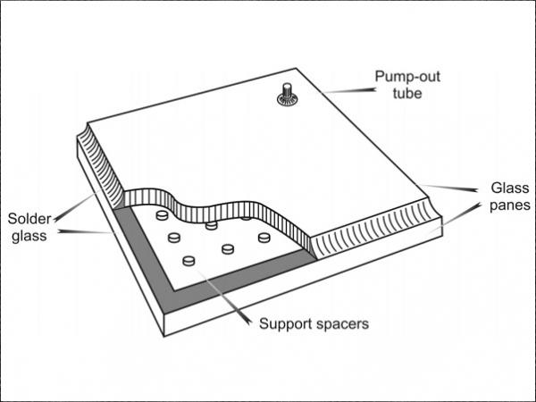
A unique alternative to the existing gas filled insulting glazing, is the Vacuum Insulated Glazing (VIG). The VIG consists of two panes of glass, very much like the gas filled glazing, but instead of using the gas as the insulating medium, a vacuum is established in the gap which removes the impact of gaseous conduction and convection processes. The evacuated gap is about a tenth of a millimeter wide and should be at a pressure of 0.1 Pa (0.001 Torr) or lower.
To stop atmospheric forces from bringing the glass panes into contact an array of high strength spacers are positioned in the gap to maintain a constant distance of separation between the glass panes. The edges of the panes are sealed hermetically to completely stop gas ingress and keep a stable vacuum level over a +25 yr service life.
The VIG has a long history, most of which is documented in the patent literature. It is well known that the first VIG design, which was a proof-of-product, was reported at the University of Sydney in the early 1990’s. Soon after, the first commercial product was produced by Nippon Sheet Glass, Japan, in 1996. The development of the VIG has always had the goal to be a product which is highly insulating with a thin profile and therefore light weight, where the ultimate market impact will be high for new and old buildings [5-8]. Over the past thirty years a considerable amount of work has resulted in an in-depth understanding of the VIG technology [5-15].
The single most important design condition to satisfy in any VIG design is that the overall thermal conductance is as low as possible. Even though for reasonable designs the VIG can provide a U-value as low as 0.5 W m-2 K-1, this can simply be improved further by using a hybrid design. In extreme climates most buildings have been fitted with conventional gas-filled double glazed units (and in some cases triple glazed). One highly desirable possibility is to replace a single glass pane of the conventional unit with a VIG, which reduces the overall thermal conductance of the whole insulating window considerably.
The VIG technology in all forms, standard, hybrid, and smart glass incorporated, has been a commercial product for over 20 years, yet it is still a technology that has not reached global recognition for application. On hindsight, the VIG technology matured as a product before the relevant building codes required highly insulating windows.
Nevertheless, the potential of the VIG technology has been well demonstrated and the fundamental science and engineering of the product well reported [5-15]. In particular, the last ten years has seen a significant rise in the interest surrounding the VIG technology from the glass industry. More so, there has been a much greater discussion within the community of architects, building engineers, and production equipment manufacturers.
The goal of this paper is to present an overview of the VIG technology with the focus on the current status of the design, testing, and manufacture of the VIG product, and highlight what the future might be. The discussion of these topics is centred on bringing together the past, present and future topics and issues that impact the VIG technology.
2. The Past, Present, and Future Status of the VIG technology
2.1 Background of Vacuum Insulated Glazing Design and Construction
As mentioned, the progress of the innovation and development that surrounds the VIG technology is well documented in the patent literature. The fundamental science and engineering of the VIG product has also been well reported in the scientific literature. At the University of Sydney the knowledge enabling accurate calculation and measurements of the properties of the VIG has matured and is well established.
Between the design options produced at the University of Sydney and in industry, VIG units with tempered glass, leadfree low-temperature solder glass, metal edge seals, low conductivity spacer materials, glass lamination, smart glass incorporation, hybrid VIG/gas-filled units, Triple VIG units, debris impact resistant units, metal panel laminate units, and fire rated VIG units, have been demonstrated with good success.
Ultimately the goal of a VIG is to provide high thermal insulation. Since the vacuum gap dimension is independent of the thermal resistance it provides, the VIG product is thin. Simply, the main parameters that define the U-value (centre-of-glazing) of the VIG unit are, 1. spacer size, 2. array spacing, 3. low emissivity coating, and 4. the level of vacuum in the gap. Assuming that the vacuum level is below the limit of 0.001 Torr. Figure 1 is a typical plot that shows the thermal performance of the VIG product.
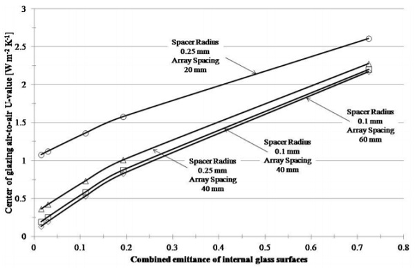
The data in Figure 1 have been validated, and represent well, the thermal performance of the VIG product. The effect of the low emissivity coating is clear and it is reasonable to expect that most manufacturers would use a good low emissivity coating, most likely only on one surface due to cost. Further reductions in the U-value will then come from changes to the spacers and the array spacing. There are issues, however, associated with these changes. Smaller spacers or larger array spacing will result in greater stresses in the glass panes, due to atmospheric pressure.
The relationship between the design parameters and the undesirable stresses in the glass panes is well understood. The last two decades of work at the University of Sydney has built-up a fundamental knowledge base, which does suggest that the issue with higher stresses is best resolved by using high strength glass panes and/or by producing spacers of a specific geometry and material (while keeping the spacer thermal conductivity low).
There is a balance that is reached between the induced stresses and the properties of the glass panes (which includes thickness) and the spacer (which includes the array spacing). The undesirable stress which are initially due to atmospheric forces and further increase because of external forces (such as thermal, wind, and debris loads) in the glass panes is of three kinds, 1. stress on the glass due to spacer contact (indentation), 2. bending stress of the glass above a spacer and over the unsupported regions between the spacers, and 3. stress at the edge of edge seal on the perimeter.
There are design options, and material options, that will provide the means to construct a VIG product that can reach a U-value as low as 0.1 W m-2 K-1, even if the weight of the unit is increased. This is also related to the combined hybrid technology and the use of the Triple VIG (TpVIG) technology. The TpVIG has been produced using the solder glass edge seal, using the technique of sealing the edge and evacuating the unit at high temperatures. In the past most of struggled with the centre pane of the TpVIG causing breaks due to the much lower heat loss in this pane relative to the outer glass panes.
At the University of Sydney, the successful design detaches the centre pane from the edge seal, and in this way the lower expansion/contraction of the centre pane does not cause stress issues in the unit. This also allows for the centre pane to be used to farm the solar energy using selective coatings on the centre glass. With the introduction of electrodes into the gap, the centre pane now has the potential to hold a transparent solar cell that can collect energy. Mostly the coupling of the TpVIG in a hybrid design will provide significantly lower U-values.
There is, however, still an issue surrounding the current manufacturing process. At this time all the commercial manufacturing lines globally, which produce commercial product, are based on a VIG design that uses a solder glass edge seal, and therefore, a batch or in-line furnace step that requires high temperatures (about 350 to 450°C) over relatively long periods (2-5 hrs). Manufacturing and energy-embodiment cost analysis performed at the University of Sydney has shown that there is a high undesirable impact of utility (energy) use in manufacturing. This results in a VIG production cost that is two to five times greater than the manufacturing cost of an Argon filled IGU product.
The current focus of much of the industry, and the academic research, is to increase the throughput of the manufacturing process, while reducing the costs. There are multiple efforts to realise a manufacturing process that can be performed at room temperature. This would reduce significantly the impact of energy use, and allow for a product that may still have a higher manufacturing cost than a traditional IGU, but will definitely allow for much lower costs in the final window installation for a residential or commercial building.
In parallel, work has continued in changing the design of the VIG and the components used to produce the VIG. In the following sections it will be shown that innovations of the glass panes, the spacer material, and the edge seal material, have led to VIG designs that can provide very low U-values.
2.2 The Glass Panes
Simply, the thermal resistance of the VIG can be increased by increasing the spacing between the spacers (equivalent to reducing the number of thermal bridges caused by the spacers between the glass panes). However, the unsupported glass between the spacers will deform and result in high levels of uniform isotropic stress. Since the stress due to atmospheric pressure must be sustained for a +25yr service life, the level of acceptable stress in annealed float glass is quite low (generally accepted to be somewhere between 8 and 20 MPa when reviewing the ASTM, ISO and CEN standards for long term stresses in float glass).
This results in a maximum allowable array spacing (in 3mm glass) that is about 20-25mm at the low end of the stress limit. Of course, by increasing the thickness of the glass a greater spacing is acceptable. Nevertheless, since the primary stress of issue is the bending of the unsupported regions of glass, and to keep the weight low, toughened glass is the choice of most manufacturers for a VIG design which uses a greater array spacing. In particular, for reason of ease of production and the added potential of ‘safety glass’, fully thermally toughened float glass is preferred.
There are several issues with the use of thermally toughened glass, however; 1. undesirable annealing of the residual temper stress during VIG production, 2. undesirable amounts of out-of-flatness in the glass panes, and 3. unable to meet the standards of safety after VIG production (undesirable fragmentation due to the effect of rigidly bonded edge seal).
Work at the University of Sydney, and other work reported in the patent and scientific literature, have defined well the annealing rates in tempered glass, which is exposed to further heat soak cycles. For no loss of temper, over heating times greater than 30 mins, the toughened glass should not be exposed to temperatures over 360°C. And, for a one hour exposure and a temper loss no greater than 20%, the maximum allowable temperature would be about 400°C.
The out-of-flatness of the thermally toughened glass will potentially result in non-uniform contact of the glass panes over the spacer array. This is undesirable above a limit because contact forces, and therefore, stresses in the glass will be non-uniform and potentially result in uncontrolled failure rates in the VIG product. Much of the past decade of work at the University of Sydney has shown that thermally toughened float glass can be produced with acceptable levels of bow, wave, and kink distortions suitable to produce a stable and durable VIG product.
Many production lines globally use thermally toughened tempered glass. This means that from these facilities it is possible to commercially produce VIG product today with a U-value of about 0.4 to 0.6 W m-2 K-1. For most of the production facilities there is still, however, an issue with the solder glass material; that is, outside of Asia, and most likely in Asia in the near future, lead based solder glass is not acceptable. A priority within solder glass development is to provide a lead-free low temperature (below 300°C) solution that will allow ease of incorporation of tempered glass, and reduce the heating time of production.
2.3 The Edge Seal
At this time the VIG manufacturing facilities that produce VIG units at or above 30,000 m² per year, use solder glass material as the edge seal. This method of production has been proven and provides clear advantages in reproducibility and durability with respect to the hermetic edge seal that is fundamental to the VIG product. It is the focus of most, if not all, producers to transition to lead-free solder glass that can be used effectively used with thermally tempered glass. This will result in VIG product that has a lower U-value limit and greater mechanical strength.
There are no limiting factors in using solder glass with thermally tempered glass, where the temper of the glass is not affected. The lead-free and low temperature solder glass product is available and has been shown to work well. However, there is still a considerable cost to the heating step, and more so the added cost of the specialty solder glass.
As with most technologies there are advantages and disadvantages. Solder glass will always be a size independent method of hermetically sealing the glass panes that is also rigid and strong. The greatest disadvantage is the cost impact of constructing the furnaces and energy use is heating the glass. There is also an argument against solder glass because of the rigidity at the edge seal resulting in bowing of the VIG product under a temperature difference. In certain cases the bow may restrict the mechanism of moving windows or sliding glass doors. More importantly, bowing produces edge stresses that could result in unit failure.
The use of a flexible edge seal, and in general, the use of a solder glass free edge seals, has been the focus of several groups over the past two decades. In all cases the edge seal is a metal formed edge seal which utilises metal alloys of different types, bonded to the glass either by ultrasonic soldering, anodic bonding, ultrasonic welding, or surface soldering. The aim is to provide a means of establishing a hermetic seal at room temperature, and have compliance at the edge so that the glass panes are free to expand relative to each other when exposed to a temperature profile.
Even though some groups have not been able to show good reproducibility and scale-up to manufacture, other groups have had good success and show excellent progress to a room temperature manufacturing process. This next-generation of edge seal has the potential to lower the overall cost of manufacture significantly (no costly solder glass and no cost of establishing and running a heating step), while providing the essential vacuum durability that is absolutely necessary. However, care must be taken with the spacer material, design and array dimensioning, since the induced contact stresses due to spacer indentation are greater with the flexible edge seal concept when glass bending results, and thus, the VIG unit can exhibit lower overall mechanical strength.
2.4 The Spacer Array
The spacer is a critical component of the VIG product. It is used to maintain a welldefined gap between the glass panes, and as such must be well-defined in size, geometry, and properties. The array must sustain atmospheric pressure over +25yrs, and not fail when periodic external loads act on the VIG, such as wind and thermal loads. Typically, the spacer is made from a high strength metal and is disk shaped, between about 0.3 and 0.5 mm in diameter and 0.2 mm in height. Clearly, the spacers are a thermal bridge between the glass panes, and thus, fewer of them decrease the overall thermal conductance through the VIG.
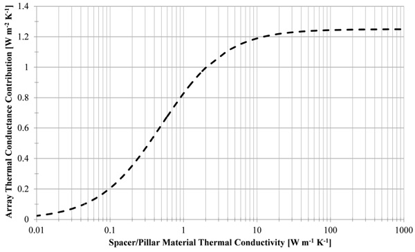
However, decrease in size or number will result in higher levels of stress in the glass due to the contact and glass bending. Figure 2 is a plot that highlights the advantage of using a lower thermal conductivity material for the spacer. If the material were to trend towards a thermal conductivity equal to the glass then the thermal conductance of the array would be about 30% lower.
Several groups have worked on spacer concepts where the fundamental goal has been to use a ceramic or glass material, with high mechanical strength, good production tolerance on shape and size, and also to remove the potential manufacturing bottle neck in the placement step of the array on the glass surface. Two significant technologies that has emerged is 1. the ceramic spacer [16] and 2. the laser formed surface feature [17].
Both of these spacer types have reported a 20-30% decrease in the individual spacer thermal conductance. The ceramic spacer has also been produced with a fine surface topography that produces greater thermal resistance. It is of high compressive strength and can be produced with a high tolerance on size and shape.
The laser feature, clearly, will be a spacer concept that offers the lowest thermal conductivity and also can be produced with a high tolerance on size and shape. The processing with the laser has two strong advantages; 1. there is no need for a mechanical placement step, and 2. the laser process will work on any shape and size of glass.
The ability of the laser process to use an arbitrary methodology to define and produce a spacer array on a glass sheet of no predefined shape and size, is an effective process to bring about a turnkey solution for VIG manufacturing. There will still be issues of initial investment and the total speed of the manufacturing process, and thus, ultimately the production cost per square meter.
Many producers have opted to use techniques of printing spacers (e.g. dispensing of paste material or screen-printing of the paste which is heat treated to harden). This is a good technique which compromises on increasing speed and lowering cost, and the size and shape of glass pane that can be processed.
Inevitably all producers will have to understand and account for issues with the contact stresses that are induced at the spacers because of atmospheric pressure and other external loads. These contact stresses result from a complex additive outcome of local lateral and transverse forces. Most, if not all, will deal with the issue by use of a surface coating that lubricates the contact and reduces the contact stresses.
In essence the available solutions will need to be put into context, and thus, each will have its place relative to the VIG design and manufacturing process that is deemed economic by producers. What is of greater concern is the potential designs and manufacturing methods, and that the different products in the market meet a globally accepted standard of quality and performance.
2.5 Design and Performance Quality Assurance
Even though the VIG technology has been commercially available for two decades, there has not been that global effort to produce a set of design, manufacturing, and performance, standards. It is, however, important that not only local market standards are produced, but global ones too.
Since 2016 the need for a global initiative has taken hold. Groups within the European and North American markets, as well as in Asia, have put in place programs to deliver standards for the VIG. For example there is an International Standards Organisation (ISO) effort within the TC160 committee (Standardization in the field of glass in building, including terminology, performance requirements and methods of calculation and test, design and construction rules, classification and specification of materials, including dimensional properties) to provide working standards for the VIG.
The ISO is this year (2018/19) publishing a standard that details the process of measuring the U-value of products and using such measurements to determine longevity. It is now working on the thermal load testing of VIG product to define the mechanical performance, and will continue onto issues such as wind load, debris impact, etc.
There are also efforts led by the American National Standards Institute, and the National Fenestration Rating Council, in North America. It is highly likely that over the next few years these bodies, and others, will produce standards that will clearly outline the acceptable quality of VIG product for the building markets. This will most likely also impact the use of VIG in other areas too, such as in the fridge door market.
The greatest difficulty, however, is in normalizing the VIG design and manufacturing process. Even though, these two areas are not of interest to the standards bodies, innovation in design and manufacturing needs to grow. It is of utmost importance that the issue of production cost be well understood so that changes can be introduced to lower costs. Ultimately, there is an indication from groups, such as the Department of Energy, USA, that the VIG must reach a U-value as low as 0.4 W m-2 K-1, at a production cost that is no greater than the Argon filled IGU.
2.6 Manufacturing
The manufacturing process that was invented at the University of Sydney and has a proven track record within the decades of commercial production in Japan, is based on an edge seal technique that requires high temperatures; solder glass. The reproducibility of the edge seal quality and the ability to process simultaneously different unit sizes, and shapes, is of great advantage.
The disadvantage is the energy and time required to produce a set of units. Even though many units can be produced in a single heating step, the process does consume a large amount of energy. Work at the University of Sydney has shown that the major impacts on unit cost are due to on-site utilities (electricity and gas use), labour, transportation, and packaging; where the on-site utility impact on cost is as high as 80% in some cases.
Currently there are several high capacity manufacturing lines; in Japan, China, Taiwan and the USA. These facilities in general use the solder glass techniques with batch processing to produce units for the building and refrigerator markets. There are other groups in Europe that are working towards manufacturing in the very near future. Certain groups are using a non-solder glass edge seal technique. These non-solder glass edge seal techniques have been shown to be effective, with companies in the European Union, Japan, China and the USA moving towards full commercial manufacturing.
Presently there are several options that will be the foundation for a low cost manufacturing process, which will compete with current IGU costs. These solutions focus on low temperature solder glass with in-line processing, metal edge sealing with in-line processing, and a hybrid in-line batch process with metal or solder glass seals. There is strong competition to solve the problem of cost and to bring the VIG product to the global market. With the possibility of replacing the existing gas filled technology with the VIG, the returns for the manufacturer with the right solution is very high, since the global insulating window market was estimated to be about $40 Billion USD in 2015.
It is reasonable to expect that by 2025 not only will the primary glass producers, such as Nippon Sheet Glass, Asahi Glass, SaintGobain, Guardian, etc., have R&D established into VIG and/or manufacturing, other smaller producers will also become direct manufacturers. That is, smaller manufacturers would be willing to directly replace existing small scale IGU lines with VIG technology if the economics of the change-over are workable.
Recently, discussions held by architects, building engineers, equipment manufacturers, and the policy institutions (such as the Department of Energy in the USA), highlight the growing acceptance that the VIG has the potential to deliver the energy saving impact needed for future sustainable building use.
3.0 Summary
The VIG technology has a long history in the patent literature, with the first proof-of-product demonstrated at the University of Sydney in the early 1990’s. Since commercialization, and the change in building codes for sustainable energy use, other groups have seen the potential of the VIG product and made significant progress in developing other VIG designs. Currently, the VIG technology is mature, there are numerous options in design and manufacturing for lower U-values and lower costs. What is currently of great interest is that policies in Europe and the changing policies in North America mandate (at least for new buildings) a window U-value that is below 0.7 W m-2 K-1.
Together, this is now driving greater competition within the glass industry to develop the next-generation VIG that will ultimately replace the existing gas filled glazed IGU. The future, however, lies in the implementation of the hybrid gas-VIG window concept, greater reduction in cost, and a greater development of the understanding of the industry and public about the VIG technology. There is the greatest outcome that with lower costs the VIG could have a huge impact on the retrofit market with existing buildings, not only in cold climates, but also in moderate-to-cold climates.
Acknowledgements
This work gratefully acknowledges access to the Sydney Informatics Hub high performance computing facility ARTEMIS at the University of Sydney and access to the INTERSECT national facility for high performance computing resources.
References
[1] Y. Xing, N. Hewitt, and P. Griffiths, Zero carbon buildings refurbishment – A hierarchical pathway, Renewable and Sustainable Energy Reviews, 15, 3229-3236, 2011.
[2] L. Pérez-Lombard, J. Ortiz, and C. Pout, A review on buildings energy consumption information, Energy and Buildings, 40, 394-398, 2008.
[3] D. Arasteh, S. Selkowitz, and J. Wolfe, The design and testing of a highly insulating glazing system for use with conventional window systems, Journal of Solar Energy Engineering, 111, 44-53, 1989.
[4] International Panel for Climate Change, 4th and 5th Assessment Report – Summary for Policy Makers
[5] R. E. Collins, G. M. Turner, A. C. Fischer-Cripps, J.-Z. Tang, T. M. Simko, C. J. Dey, D. A. Clugston, Q.-C. Zhang, and J. D. Garrison, Vacuum glazing – A new component for insulating windows, Building and Environment, 30[4], 459-492, 1995.
[6] T. M. Simko, A. C. Fischer-Cripps, and R. E. Collins, Temperature-induced stresses in vacuum glazing: Modeling and experimental validation, Solar Energy, 63[1], 1-21, 1998.
[7] R. E. Collins, A. C. Fischer-Cripps, and J.-Z. Tang, Transparent evacuated insulation, Solar Energy, 49[5], 333-350, 1992.
[8] R. E. Collins and T. M. Simko, Current status of the science and technology of vacuum glazing, Solar Energy, 62[3], 189-213, 1998.
[9] P. C. Eames, Vacuum glazing: Current performance and future prospects, Vacuum, 82[7], 717-722, 2008.
[10] P. W. Griffiths, M. di Leo, P. Cartwright, P. C. Eames, P. Yianoulis, G. Leftheriotis, B. Norton, Fabrication of evacuated glazing at low temperature, Solar Energy, 63[4], 243-249, 1998.
[11] S. Papaefthimiou, G. Leftheriotis, P. Yianoulis, T. J. Hyde, P. C. Eames, Y. Fang, P.-Y. Pennarun, P. Jannasch, Development of electrochromic evacuated advanced glazing, Energy and Buildings, 38[12], 1455-1467, 2006
[12] J. F. Zhao, P. C. Eames, T. J. Hyde, Y. Fang, J. Wang, A modified pump-out technique used for fabrication of low temperature metal sealed vacuum glazing, Solar Energy, 8[9], 1072-1077, 2007.
[13] H. Manz, S. Brunner, and L. Wullschleger, Triple vacuum glazing: Heat transfer and basic mechanical design constraints, Solar Energy, 80[12], 1632-1642, 2006.
[14] L. Wullschleger, H. Manz, K. Ghazi Wakili, Finite element analysis of temperature-induced deflection of vacuum glazing, Construction and Building Materials, 23[3], 1378-1388, 2009.
[15] M. M. Koebel, H. Manz, K. E. Mayerhofer, B. Keller, Service-life limitations in vacuum glazing: A transient pressure balance model, Solar Energy Materials and Solar Cells, 94[6], 1015-1024, 2010.
[16] T. Collier, M. Vogel-Martin, L. Pekurovsky, T. Hoffend, S. Howard, J. Mansheim, K. Humpal, and M. Lu, Glass Performance Days Finland, pp.54-56, 2015.
[17] A. Streltsov, J. Kim, L. Masters, and D. Lance, Glass Performance Days Finland, pp.280-283, 2017.


")