Challenging Glass 6
Conference on Architectural and Structural Applications of Glass
Louter, Bos, Belis, Veer, Nijsse (Eds.), Delft University of Technology, May 2018.
Copyright © with the authors. All rights reserved.
ISBN 978-94-6366-044-0, https://doi.org/10.7480/cgc.6.2118
Authors:
Faidra Oikonomopoulou a, Telesilla Bristogianni a, Lida Barou a, Erwin Jacobs a, Giulia Frigo a, b, Frederic A. Veer a, Rob Nijsse a
a Delft University of Technology, The Netherlands,
b Politecnico di Milano, Italy
Cast glass components are a promising solution for engineering pure glass structures of high transparency and load-carrying capacity due to their large cross-sectional area and monolithic nature. Currently, the few realized structures employing cast glass components rely either on a steel substructure or on an adhesive of high bonding strength and typically less than 2 mm thickness, to ensure the stiffness and stability of the construction.
Whereas the first solution compromises the overall level of transparency, the second results to a permanent construction requiring intensive and meticulous labour and extreme accuracy. This paper explores the potential of a novel, reversible all-glass system comprising dry-assembly, interlocking cast glass components as a promising and sustainable solution that can avoid the above-mentioned challenges.
Owing to its interlocking geometry, the proposed system can attain the desired stiffness and stability with the aid of minimal, if any, metal framing. Furthermore, the suggested system circumvents the use of adhesives by using a dry, colourless interlayer as an intermediate between the glass components to accommodate any dimensional tolerances and allow for an even load distribution; moreover, it allows for the disassembly and circular use of the components.
To validate the concept, different component geometries and interlocking mechanisms are developed. As a proof of concept, the most promising interlocking forms are kiln cast in 1:2 scale and assessed in terms of mechanical interlocking capacity, mass distribution, residual stress generation and ease of fabrication. In parallel, research is conducted on different materials for the dry, transparent interlayer.
From the developed designs, blocks with osteomorphic interlocking mechanisms are selected as the most promising concept and are further assessed by numerical modelling to study the influence of the interlocking geometry to the overall structural performance. The results highlight the structural potential of the proposed system and demonstrate its feasibility.
1.Introduction
1.1.The potential of cast glass in structures
It is only in the last decades that the structural potential of glass has started to unveil. Combining transparency with a high compressive strength, glass enables us to make diaphanous load-bearing compressive members, from beams and columns to free-standing facades and entire glass structures. Although glass’ fabrication boundaries have been continuously stretching (O' Callaghan,Marcin 2009), so far, glass structures are still confined to the shapes and dimensions that can be realized by the virtually flat elements fabricated by the float industry.
Yet there is a way to escape the design limitations imposed by the two-dimensional nature of float glass: through casting. By pouring molten glass into moulds, solid 3-dimensional glass components of considerably larger cross-sections can be obtained. Owing to their large cross-sectional area and monolithic nature, such components can form repetitive units for the construction of 3-dimensional, self-supporting glass facades and walls, sparing the necessity of an additional supporting structure (Oikonomopoulou et al. 2015a). Indeed, solid cast glass components are a promising solution for engineering pure glass structures of high transparency and load-carrying capacity; a solution that so far has been little explored.
1.2.Self-supporting envelopes out of cast glass components
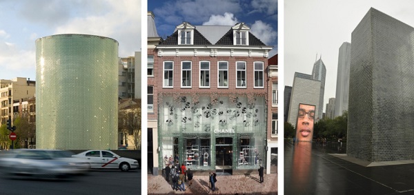
At present, there are only a few realized examples of self-supporting structures out of solid cast glass elements1 (see fig.1). The most characteristic ones are the envelopes of the Atocha Memorial (Schober et al. 2007), the Crown Fountain (Hannah 2009), the Optical House (Hiroshi 2013) and the Crystal Houses (Oikonomopoulou et al. 2017). To ensure the desired stability and stiffness of the glass assembly, these projects employ either a metal substructure or a rigid structural adhesive (Paech,Goppert 2008; Oikonomopoulou et al. 2015b) to bond the blocks together. In specific, in the Optical House, solid glass blocks are drilled and threated from below to a pre-tensioned vertical mesh of stainless steel rods (Hiroshi 2013). In this system, the glass can carry its own weight, whereas the steel mesh withstands any lateral forces, resulting to a solid glass block façade of 10 m height and just 50 mm thickness.
In the Crown Fountain, the glass block structure is supported by an internal stainless steel frame from T-profiles that carries both the weight of the walls and provides resistance to any lateral wind loads (Hannah 2009). Towards maximized transparency, both the Atocha Memorial and the Crystal Houses employ a rigid, colourless adhesive that ensures the desired stiffness and spares the necessity of any additional structure. Geometry also contributes to the overall stability. The almost cylindrical shape of the Atocha Memorial adds to the structure’s rigidity (Paech,Goppert 2008) allowing for an 8 times thicker adhesive (2mm) compared to the 0.25 mm adhesive thickness required for the construction of the Crystal Housesfaçade(Oikonomopoulou et al. 2015a), an envelope of virtually flat geometry.
Whereas the first solution of an additional substructure compromises the overall level of transparency, the second solution of a rigid adhesive results to a permanent construction of intensive and meticulous labour, as the adhesive’s limited thickness does not allow for deviations more than a quarter of a millimetre per layer of construction (Oikonomopoulou et al. 2017). Moreover, the permanent nature of the adhesive results in a non-reversible, non-recyclable structure.
1 Structures employing hollow glass blocks or solid glass blocks that are non-load-bearing are out of the scope of this research. Hollow glass blocks are generally considered non-load bearing components. Their reduced thickness results in internal buckling or stress concentrations that in turn lead to a relatively low stated resistance in compressive loading (Oikonomopoulou et al. 2017).
1.3.A novel, reversible system out of interlocking cast glass components
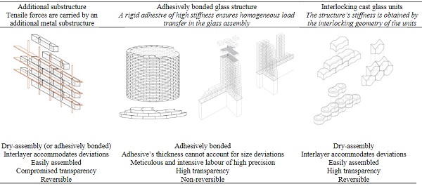
This paper explores the potential of a novel, reversible system comprising dry-assembly, topologically interlocking cast glass components that can tackle the limitations imposed by both current systems; these include the irreversibility, strict tolerances and meticulous construction process of adhesively bonded systems and the reduced transparency of constructions employing a metal substructure (see Table 1).
Table 1: Design concepts for self-supporting envelopes out of cast glass components
Indeed, casting glass enables us to generate a wide range of shapes, including geometries with interlocking mechanisms, rendering them a promising solution for future applications not only in full-glass envelopes but also in other compressive structures such as columns (Akerboom 2016), arches (Aurik 2017; Snijder et al. 2016) and domes. An interlocking system out of solid glass elements, besides being fully transparent, presents several advantages in terms of structural performance and circularity. The overall stability is achieved through compression provided by the self-weight of the construction combined with the interlocking geometry that offers the needed restrains to lateral movement, resulting to a structure with minimal, if any, metal framing.
Furthermore, the suggested system circumvents the use of adhesives by using a dry, colourless interlayer as an intermediate between the glass units. In addition to preventing stress concentrations due to glass to glass contact, the dry interlayer can also compensate the inevitable dimensional tolerances in the cast units’ size. Most important, the dry-assembly design allows for the circular use of the glass components, as they can be retrieved intact and reused or, eventually, recycled as they are not contaminated with adhesives, coatings, etc.
To validate the concept, different component geometries are developed in respect to the casting limitations and the principles of topological interlocking. The most promising forms are kiln cast in 1:2 scale and assessed in terms of mechanical interlocking capacity, mass distribution, generation of residual stresses and ease of fabrication. In parallel, research is conducted on different materials for the dry, transparent interlayer. The most favourable components are further evaluated through numerical modelling. The results highlight the potential of the system and demonstrate its feasibility for future applications.
2.Definition, principles and advantages of interlocking structures in architecture
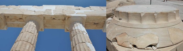
An interlocking system consists of components that employ their geometry to restrain lateral movement in a construction, whereas the whole assembly is stabilized by compressive forces – sometimes, even the self-weight of the construction is sufficient for this purpose. The idea of dry-stacked, interlocking (compressive) structures is not new in architecture. Ancient Greeks had developed ingenious dry-stacking and self-aligning systems with wooden pins and blocks in the marble column drums of the Greek temples (see fig.2) – a practice followed even in Parthenon.
The structure worked in compression and the surfaces between the marble elements were so precise and flat that the interlocking connection was practically air-tight. In several occasions the wooden pin of the column was actually found intact during restoration works. (Korres 2000). Incan walls made by irregularly shaped interlocking stone polygons allowed the assembly of stable, self-aligned, mortarless structures with high seismic resistance. Roman arches and Japanese wood joinery are other marvellous examples of traditional interlocking engineering.
A development of traditional interlocking systems is the “topological interlocking” that essentially avoids keys or connectors which can act as stress concentrators, thus reducing the overall strength of the structure, and limits the number of different components. Such a system had already been patented in 1699 by architect Joseph Abeille in his “Flat Vault”(Gallon 1734). (Estrin et al. 2011) defines topological interlocking as follows:
Topological interlocking is a design principle in which elements (blocks) of special shape are arranged in such a way that the whole structure can be held together by a global peripheral constraint, while locally the elements are kept in place by kinematic constraints imposed through the shape and mutual arrangement of the elements.
In practice, in topologically interlocking structures the modules ensure the kinematic constraint of the assembly in two directions, typically the one normal to the assembly plane and its transverse. Such interlocking systems offer several advantages over traditional construction. Their fragmented nature allows for an increased strength and structural stability in structures made of brittle materials like glass. In specific, the probability of complete failure increases with increasing size of a structural member out of a brittle material; if the member contains a critical defect it can lead to failure.
By assembling instead a structure from multiple small blocks, the probability of complete failure decreases due to the inherent redundancy: Crack propagation is confined within a block’s interfaces as the units are not bonded together; even if several of the units fail the rest are kept in place by the kinematic constraint from the adjusting blocks2 and are able to carry the load. Enhanced stability is also achieved by the ability of the units to undergo small movements within the structure. This is especially important to seismic zones as the interlocking structures are able to dissipate the vibration energy (Estrin et al. 2011): compared to a mortar masonry wall, which would act monolithically against loading, a dry interlock wall allows for resettlement of the stones.
Equally important, an interlocking system provides an easily assembled, multifunctional and reversible structure. The self-aligning nature of such structures allows blocks to fit into each other without adjustment, increasing the construction productivity and the resulting quality of the assembly. Reversibility is perhaps the most important feature in the case of glass components. According to a research made by (Eurostat 2014), glass waste is currently the second largest waste material in the European Union, even though it can be endlessly reused and recycled - if it is free of contaminants, including adhesives or coatings. A reversible, dry-assembly, interlocking system promotes the dismantling of the assembly and the reusability of the components since they can be retrieved intact. Moreover, the circumvention of an adhesive bonding and thus, of contamination, facilitates the recycling of the components.
2 This principle is relevant to the specifics of the block shape and the pattern of assembly and is not valid in all interlocking geometries. E.g. in a roman arch, if the key component fails, the arch will collapse.
3.Design criteria for the interlocking cast glass components
So far, interlocking systems out of cast glass components have been very little explored and only in a theoretical framework without a thorough establishment of design criteria in respect to the casting process and the material glass. (Aurik 2017; Snijder et al. 2016) have studied a dry-assembled arched glass masonry bridge where interlock is achieved only in one direction. (Akerboom 2016) has proposed a design for an interlocking cast glass column, whereas (Barou et al. 2016; Frigo 2017; Jacobs 2017), have developed alternative interlocking brick systems for the transparent and reversible restoration of historic monuments.
As already mentioned, dry-stack masonry systems already exist in various materials, such as wood, stone and terracotta. However, we cannot simply adapt the existing interlocking geometries to glass, as these have been developed considering different manufacturing processes and material properties. Therefore, a series of design criteria are established for the interlocking cast glass components taking into account the principles of existing topological, dry-stack systems but reformed to fit the characteristics and peculiarities of cast glass as a construction material. These requirements are thus divided into criteria for the establishment of topological interlocking and criteria imposed by glass as a material and by casting as a manufacturing process:
3.1.Design criteria related to topological interlocking
Based on the principles of topological interlocking, the designed units should fulfil the following criteria:
- Movement confinement in both axial and transverse direction
To enhance the monolithic behaviour of the assembly and ensure the desired redundancy of the structure, the interlock mechanism should confine both planar direction movements.
- Optimizing shear capacity
Interlocks following smooth convex curvatures are preferred as they allow for a more homogenous distribution of the shear forces occurring at the interface area. Traditional connectors or keys with comparatively much smaller cross-sectional area compared to the gross cross-sectional area should be avoided as they result in concentrated stresses. The existence of such parts might be acceptable to a certain level for ductile materials. But the unforgiving nature of a brittle material like glass implies the avoidance of such concentrated stresses in keys and connectors that can lead to premature failure.
- Self-alignment
The interlocking mechanism should assist the units to self-align, allowing for an easy and fast construction of high quality. In this direction, convex contact areas provide self-adjusting properties as well as reduced stress concentrations.
- Multifunctionality
Towards multifunctionality it is important to consider a unit geometry that permits multiple configurations of stacking; for example one single unit can be designed to generate both wall and column structures.
3.2.Design criteria imposed by the material and by its casting process.
- Limited volume
In theory casting enables us to create monolithic glass elements of any form and cross-section. Nevertheless, the meticulous and excessively time-consuming annealing process of cast glass can jeopardize the marketability of the components and render them financially unsustainable. To this end mass is a critical aspect. The larger the component, the exponentially longer the annealing time. For example, the solid glass bricks of 65 mm × 210 mm × 105 mm in dimensions and 3.6 kg weight used in the Crystal Houses façade required 8 h of annealing, whereas components of double the volume, 65 mm x 210 mm x 210 mm and 7.2 kg weight, required an annealing cycle of 36–38 h respectively (Oikonomopoulou et al. 2017).
Even larger components can demand up to several months of controlled annealing: for example the Opposites of white drum-shaped cast sculptures by artist Roni Horn, each 50.8 cm high by 142 cm diameter, required 4 months of controlled annealing to prevent the generation of residual stresses (Kroller-Muller Museum 2007). Hence, for this research, solid cast glass elements are designed within a 10 kg mass limitation androughly corresponding to the size range of standard masonry units.
- Rounded shape and equal mass distribution
Regarding the overall geometry, a rounded shape and an equal mass distribution are key aspects for the prevention of concentrated residual stresses. Glass is known to prefer an ellipsoid, egg-like shape when cast. A curved, convex geometry is thus preferred over sharp, pointy edges where internal residual stresses can concentrate due to inhomogeneous shrinkage3. To further prevent inhomogeneous annealing it is important that the unit maintains an equal cross-sectional area throughout. This way the brick can gradually cool down uniformly, preventing the generation of residual stresses due to inhomogeneous shrinkage of the material. In this direction, projections such as small connectors or notches should be avoided as well.
- Limited number of different units
Lastly, in order to facilitate the production and assembly of the structure and limit the manufacturing costs, a repetitive geometry of the components is preferred. This allows for the manufacturing of a limited amount of moulds and for a standardized production process. Assembly becomes easier as each brick can take any place in the structure, instead of predefined locations, as is the case with systems featuring multiple geometries, such as the Incan walls. A single geometry is favoured but configurations with a limited number of different elements (preferably between 2 to 3) are considered effective as well.
3 Edges generally cool faster due to exposure in cooling from multiple sides. The core cools relatively slower, creating residual stresses at the edgesdue to the difference in natural shrinkage. An ellipsoid shape thus is favourable as it allows for homogeneous cooling and correspondingly to an even shrinkage rate.
4.Interlocking designs and prototypes
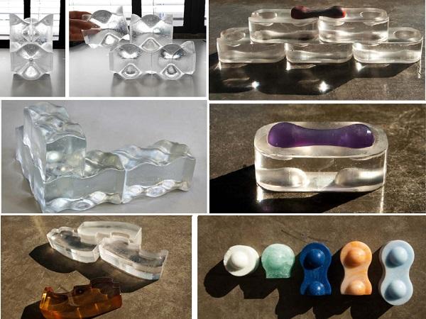
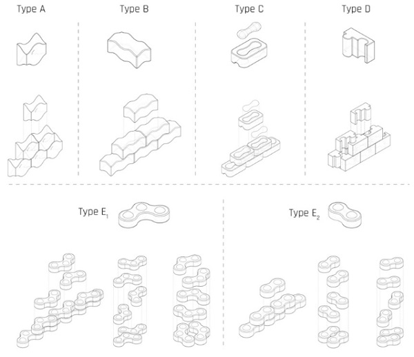
Based on the above criteria, several different interlocking designs are developed to explore the potential of variable interlocking mechanisms. The developed designs can be seen in Fig. 3. 1:2 scale glass prototypes using the kiln-cast method are manually produced to assess the different designs in terms of mechanical interlocking capacity, mass distribution, generation of residual stresses and ease of fabrication. The prototypes can be seen in figures 4-8.
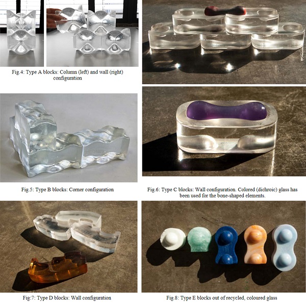
- Types A & B: Osteomorphic blocks – vertical stacking
Type A and B follow an osteomorphic geometry as described by (Estrin et al. 2011). These shapes have been engineered with non-planar concave-convex surfaces that allow for full contact between the elements, and thus a homogeneous load distribution, whilst impeding relative movements in both axial and transverse directions. The symmetry of the interlocking design in both planar directions allows the use of the same component parallel or rotated by 90 degrees to the one placed below. Thus, corners can be easily obtained with the same block unit. The assembly of the structure can be easily achieved by stacking the blocks on top of each other. Only the blocks on the periphery need to be constrained separately.
- Type C: Two-component interlock – vertical stacking
In this system interlocking is achieved through a male and a female component. This design provides more freedom in terms of material use and visual aesthetics; one component can be glass and the other can be e.g. metal, plastic or coloured glass. Materials can also be selected to match the stress distribution of the mechanism; it is anticipated that stresses will not be even in the components due to their different geometries. Annealing is considered to be homogeneous for the bone-shaped component because of its relatively even mass distribution and ellipsoid ends. The block-shaped component requires a more meticulous annealing cycle to prevent internal residual stresses due to its relatively inhomogeneous mass distribution. This design does not allow for the creation of corners in the structure with the same elements, due to the block’s non-symmetrical interlock in the transverse direction. Again, a peripheral constraint is necessary for stabilizing the structure.
- Type D: Puzzle brick - Vertical sliding
This design follows a different interlocking mechanism where the components slide vertically to each other. In particular, the components are positioned halfway in height and width in relation to their adjusting components. In this way, continuous joints -weak zones susceptible to stress concentrations- are avoided. Compared to the previousinterlocking mechanisms, this system restricts the self-alignment of the bricks in both planar directions and thus, decreases its damping properties. In addition, the relatively complex shape of this unit may result to internal residual stresses during the annealing and cooling process of the cast element, as well as to local stress concentrations during loading. As with type C, corners cannot be achieved in the structure with the same component due to its asymmetricalinterlocking mechanism.
- Type E: Rotational brick - Vertical stacking
The almost semi-spherical key of this geometry provides more flexibility in the form of the overall assembly compared to the previous solutions. For example, the same modulus can be used to make either planar or cylindrical structures. The two different block types (E1 and E2) can also be combined together to create one structure. The cylindrical structure spares as well the necessity of a peripheral substructure, as the desired rigidity is secured through the totalshape. This block type provides satisfactory homogeneous annealing due to its curved geometry. However, the considerable projections of the semi-spherical connections may result in local shear stress concentrations during loading.
A summarized assessment of the different interlocking designs based on the design criteria can be seen in Table 2below.
Table 2: Assessment of the different interlocking block types in terms of design criteria
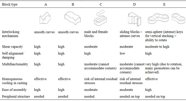
Out of the developed designs the osteomorphic blocks, types A and B, are considered the most promising solutions due to their multifunctionality, ease of assembly and inherent ability to prevent peak stress concentrations, both duringthe casting process and during loading. In specific, the smooth curves and even mass distribution of the componentsallow for their homogeneous annealing preventing the generation of internal residual stresses. The smooth concave-convex interlocking mechanism of the elements ensures its high shear capacity as well. Even though stress concentrations may occur to the concave parts of the surfaces upon loading, these are likely to be negligible compared to the ones occurring in small keys or connectors (Dyskin et al. 2003).
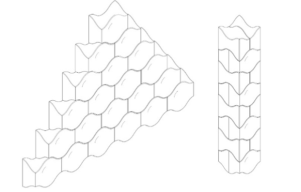
The system also has high damping properties: restricted movements of the blocks relative to each other are still permitted, allowing for self-alignment and dissipation of energy in case of seismic loading. Moreover, the redundancy of this type of blocks has been proved before by (Dyskin et al. 2003). Such a system is highly tolerant to local failures and it has been demonstrated that after the collapse of random blocks the structure can resist by percolation of damage until nearly 25% of block failure. Lastly, in terms of multifunctionality, the symmetry of the osteomorphic blocks in both planar directions allows their assembly in configurations with 90 degrees rotations, achieving for example columns and wall corners, as shown in fig.9. Types A and B are therefore favoured in terms of structural behaviour and manufacturing process.
5.Dry interlayer
Dry-stacked glass under axial load is never expected to fail due to its compressive strength limit. However, unevenness or imperfections at the contact surface of the components caused during manufacturing, result in local (tensile) stress concentrations due to the inability of glass to yield by plastic deformation. The inherent brittleness of glass, as a consequence, can respond to such peak stresses with crack propagation and failure in much lower stress values than its stated compressive strength.
This has been demonstrated also by axial compressive tests by (Oikonomopoulou et al. 2015a) performed to glass bricks with direct contact that failed in an average compressive stress of 20-30 MPa. In traditional masonry systems the mortar accommodates such dimensional intolerances of the components and ensures an even load distribution. In the case of dry-stacked interlocking glass components, this function can be addressed by a resilient interlayer that can accommodate any micro-imperfections or size tolerances and redistribute evenly the stresses on the contact area.
In the glass industry, interlayers have been commonly used for laminating glass. For this process polymer materials such as Polyvinyl butyral (PVB), ionoplast polymers (SentryGlass Plus), Ethylene Vinyl Acetate (EVA) and polyurethane (PU) are mainly applied. These interlayers present excellent optical qualities but are selected for a different process and mechanical performance than the one desired for dry-assembled structures. In laminated glass, the interlayer’s main structural role is to transfer the shear stresses among the glass panes and withstand dynamic or cyclic loads (e.g. wind or hard-body impact), whereas in an interlocking, dry-assembled glass structure the interlayer will be mainly subject to static compressive load.
In addition, the interlayer should be able to adapt by deformation to the surface asperities. Thus, the main criteria for this application are the behaviour of the material under long-term loads, its time-dependency response and creep resistance. The two most critical properties of the interlayer material are therefore its Young’s Modulus, which should be relatively lower than that of glass, and its hardness4. Except ofthese two properties, the following requirements are considered for the selection of the interlayer:
- Transparency and durability to UV-lighting - so that the overall transparency level is not compromised by the dry interlayer
- Good behaviour under static long-term compressive load
- A compressive strength higher than 10 MPa
- Ability to be formed in a consistent thickness in the shapes corresponding to the interlocking components
- A consistent thickness of at least 2-3 mm to compensate for any dimensional tolerances
- A maximum service temperature of 50° C
4 The interlayer should have less resistance to being deformed elastically than glass in order to account for asperities in the glass’s surface. Thus, a lower Young’s Modulus value is essential. If the hardness is too low the interlayer will be easily penetrated risking direct contact of the glass components. If the hardness is too high, the interlayer will not be able to adapt to the micro-scale shape of glass, leading to an uneven load transmission and localized contact area.
According to CES Edupack 2015 program (Granta Design Limited 2015) the following thermoplastic and elastomer polymers fulfil the above-mentioned criteria:
- PEBA – Polyether block amide
- PU - Polyurethane (rubber)
- PVC – Polyvinyl Chloride (soft)
- TPU – Thermoplastic polyurethane
These materials can be processed to the desired shape either by injection moulding or extrusion. Polyurethane, PVC and TPU have already been investigated in terms of structural behaviour and have been applied in the building envelope industry. TPU, used in laminated glass, only obtains its mechanical properties after it has been thermally processed, thus is not considered appropriate for this study. Thus, PU rubber and soft PVC are considered the most suitable materials. Experimental work by (Aurik 2017) in PVC, PU70 and PU90 proved that PVC’s E modulus is strongly time-dependent and creep occurs under static loads. Moreover, there is discoloration (to a yellow hue) of the material under long UV-exposure.
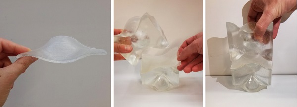
Therefore, PVC is considered unsuitable for this research. Experiments with PU70 proved that its E modulus is time-independent and its high stiffness requires a thicker interlayer; which is desirable in the presented application for the accommodation of size deviations. The experimental results were inconsistent for PU90 and showed an irregular contact area pattern under high compressive loads. Hence, among the analysed samples, the most promising material for the dry interlayer is considered to be PU70 rubber which can be cast to the desired shape in a uniform thickness. A prototype of a 3mm thick, cast PU70 interlayer, manufactured for the type A blocks, can be seen in fig.10.
6.Optimization of the interlocking geometry of the osteomorphic blocks by numerical modelling
As discussed in chapter 4, interlocking blocks following an osteomorphic geometry are selected as the most promising components. To further assess the influence of the most crucial geometrical aspects of the interlocking mechanism, such as the amplitude and the brick height on its performance and structural capacity, a numerical model is made for the block types A, B5. The geometry of the block is generated through the Grasshopper plug-in for Rhinoceros.
This plug-in allows for automatic generation of new geometries by changing certain input parameters. The model variations are then exported as a solid, using a STEP-file; and imported into DIANA FEA, a finite element software. The currently used values for Poisson’s ratio and Young’s modulus are calibrated using experimental research by (Aurik, 2017), and hence are only valid for a PU with a hardness of 70 Shore A. Harder polyurethanes would have an increased stiffness and incompressibility, which affects the spreading of the stresses negatively and decreases its tolerance for imperfections and vice versa.
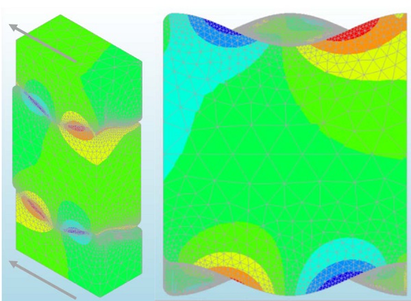
The variation models are evaluated using the Christensen’s failure criterion output, which essentially converts theprincipal stresses and its material properties into a failure envelope definition, including a limitation for the tensile capacity of brittle materials (Christensen 2013). Loading the interlocking brickwork in shear (as shown in Fig. 11), the generated contour plots then show how tensile peak stresses are spread on the contact surface.
Moreover, as only a quarter of the brick is modelled (using its symmetric properties to reduce calculation time) the reaction forces yield its shear lock capacity. Hence these contour plots can be used to indicate: 1) where flaws in the geometry would be most influential (tensile opening of cracks); 2) how stress concentrations spread onto the contact surface; and 3) the stress gradient at sections in the geometry. By evaluating both the contour plots and the shear lock capacity one then can evaluate multiple geometries and geometry variations on its applicability as a cast glass interlocking brick.
5 A more detailed study regarding the presented numerical model can be found in (Jacobs 2017). The numerical model corresponds in both types, since Type B block is generated by multiplying Type A. It is expected that compared to type B, type A blocks will present a slight decrease in load capacity due to extra eccentricity in loading.
Numerical modelling showed that any compressive load puts the geometry in a compressive state and hence yields higher shear capacities compared to when no compressive force was applied. Hence all variants were tested without any compressive load; instead the shear-load-inducing bricks were vertically constrained.
It was proven numerically that a higher amplitude would increase the contact area for stresses to spread on, while reducing the uplifting behaviour by increasing its slope. A negative effect of an increase in amplitude is that a higher precision of the brick geometry is required, as the failure limit was reached at a smaller deformation. A deviation from the perfect geometry would hence lead to failure earlier, in contrast to the lower amplitude variations. A very small amplitude however would result in uplifting to become a crucial factor, needing a heavier top constraint and relying more on friction than on the interlocking geometry. The choice for a higher amplitude is therefore considered a trade-off between a higher shear capacity and a reduction in uplifting behaviour on the one hand, and geometry precision (and hence post-processing) on the other hand.
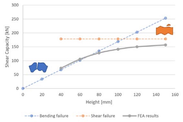
The height of the brick is expected to have direct influence on the failure mode of the glass brick. A too thin brick of glass would gain more stresses due to eccentric loads (failure through bending), while higher bricks are more resistant to this, leading to shear key failure (failure through shear). These failure mechanisms are expected to occur in the most flaw-prone area, as will be gained from the Christensen’s failure criterion. Thus, the upper boundaries were determined from a simplified hand calculation using the characteristic strength of glass. It is expected that the real value lies somewhere below, as the combination of the principal stresses in the Christensen’s criterion lead to failure before reaching this characteristic value.
The results from the finite element analysis versus the simplified hand calculationsare depicted in Fig. 12. The graph shows indeed failure through bending to be critical in lower brick heights, while failure through shear becomes more influential with higher bricks. Regarding geometry tolerances, higher bricks are also advantageous, as the failure load occurs at a larger deformation. This means a larger geometry deviation is allowable when producing the interlocking bricks when compared to thinner bricks. Hence a higher brick is beneficial for brick design, as capacity is increased, tolerances can be slightly higher and there is a higher chance on a more preferred failure mechanism, as an interlock chipping off would leave a part of the brick intact for increased structural integrity.
7.Results & Discussion
Cast glass is a promising new material for creating transparent structures of considerable monolithic thickness that can take full advantage of glass’s inherent compressive strength. Nevertheless, the meticulous and time-consuming annealing process of cast glass imposes practical limitations to the size of the cast components that can be considered cost-efficient. As a result, cast glass components can be standardized to roughly the size of standard bricks. At present there are only a few realized architectural examples of self-supporting structures made of cast glass units.
These employ either a supportive substructure or a stiff adhesive to assemble the blocks together. This paper proposes a new, dry-stacked system out of interlocking cast glass components that can tackle the drawbacks of both existing systems, namely the permanent nature, strict tolerances and demanding construction process of adhesive systems and the reduced transparency of systems employing a supportive metal structure. Additionally, such a system has great prospects in terms of sustainability; its reversibility allows for the reuse or recycling of the components.
Although interlocking structures exist from the ancient times in several building materials, until now they have been little explored in glass and only in theory. In this paper, therefore, design criteria in respect to the interlocking principles as well as to the material properties and cast manufacturing process of glass are formulated. According to these, several different designs and interlocking mechanisms are developed and physical prototypes were kiln cast in 1:2 scale. The assessment of the presented designs by the aforementioned criteria suggests that blocks following osteomorphic interlocks are the most promising solution for cast glass components: they present an equal mass distribution, homogeneous annealing, multifunctionality, high shear capacity and damping properties.
A further assessment of this type of blocks through numerical modelling gives valuable input regarding the influence of the geometrical parameters of the interlocking geometry in the overall structural performance. In specific, a decrease in the height of the blocks lowers its shear capacity and alters the system’s failure mechanism. A lower brick is more susceptible to bending, whereas for higher bricks the shear lock failure is proven to be more critical. Both failure mechanisms are nevertheless sti ll possible, even for higher bricks, as peak tensile stresses occur at the middle of the block. A flaw in that area could lead to crack propagation normal to this region.
Research on different interlayer materials suggests that PU70 fits best for the presented dry-assembly glass application in terms of structural performance and shaping potential. The ability to cast PU70 allows the generation of interlayers of consistent thickness and of perplex curved geometries; such as the ones needed to match the interlocking surfaces of the osteomorphic blocks.
Further research will focus on the experimental validation of the selected designs in order for statistical data to be derived, as well as on the effect of pre-compression as a peripheral constraint structure. A more in-depth experimental work is also necessary to evaluate the mechanical response of the PU interlayer. Numerical research by (Jacobs, 2017) indicates that its properties highly affect the shear capacity and the contour plot gained through numerical modelling.
An interesting solution would be the engineering of a composite interlayer section as described by (Frigo 2017) with a softer external interlayer, to adapt to surface imperfections and displacements occurring under axial load and an inner layer that would be stiffer and more resistant. Nonetheless, the research and numerical data obtained so far, as well as the creation of physical prototypes prove the potential and feasibility of the system and encourage the next steps of development towards its application in built structures.
Acknowledgements
The authors gratefully acknowledge Kees Baardolf for his technical assistance and remarkable insight in the manufacturing of the prototypes, Francesc Arbós for providing visual material, prof. Jiyong Lee for his valuable feedback on the design concepts and Katherine Rutecki for her feedback in kiln-casting.
References
Akerboom, R.: Glass Columns, exploring the potential of free standing glass columns assembled from stacked cast elements. TU Delft (2016)
Aurik, M.: Structural Aspects of an Arched Glass Masonry Bridge. Delft University of Technology (2017)
Barou, L., Bristogianni, T., Oikonomopoulou, F.: Transparent Restoration. TU Delft (2016)
Christensen, R.M.: Theory of materials failure. Oxford University Press, UK (2013)
Dyskin, A.V., Estrin, Y., Pasternak, E., Khor, H.C., Kanel-Below, A.J.: Fracture Resistant Structures Based on Topological Interlocking with Non-planar Contacts. Advances Engineering Materials 5(3), 116-119 (2003). doi:10.1002/adem.200390016
Estrin, Y., Dyskin, A.V., Pasternak, E.: Topological interlocking as a material design concept. Materials Science and Engineering C(31), 1189-1194 (2011)
Eurostat: Waste Statistics in Europe. http://ec.europa.eu/eurostat/statisticsexplained/index.php/Packaging_waste_statistics (2014). Accessed 22 October 2017 2017
Frigo, G.: Restoration of partially collapsed historic wall using interlocking cast-glass components: the case of san michele castle in cagliari. Politecnico di Milano (2017)
Gallon: Machines et inventions approuvées par l'Académie royale des sciences. Paris (1734)
Granta Design Limited: CES EduPack 2015. In. Granta Design Limited, Cambridge, (2015)
Hannah, B.H.: Jaume Plensa: Crown Fountain as Carnivalesque. Umi Dissertation Publishing, USA (2009)
Hiroshi, N.: Residence in Hiroshima. DETAIL: Transluscent and Transparent 2 (2013)
Jacobs, E.A.M.: Structural consolidation of historic monuments by interlocking cast glass components. Delft University of Technology (2017)
Korres, M.: From Pentelicon to the Parthenon: The Ancient Quarries and the Story of a Half-Worked Column Capital of the First Marble Parthenon. Oxford University Press, UK (2000)
Kroller-Muller Museum: Roni Horn: Opposites of white. http://krollermuller.nl/en/roni-horn-opposites-of-white (2007). 2016
O' Callaghan, H., Marcin, M.: Thinking Big with Structural Glass. In: Vitkala, J. (ed.) Glass Performance Days, Tampere 2009, pp. 59-63. Glaston Finland Oy
Oikonomopoulou, F., Bristogianni, T., Nijsse, R., Veer, F.A.: Innovative structural applications of adhesively bonded solid glass blocks. In: Vitkala, J. (ed.) Glass Performance Days, Tampere 2015a, pp. 256-261. Glass Performance Days
Oikonomopoulou, F., Bristogianni, T., Veer, F.A., Nijsse, R.: The construction of the Crystal Houses façade: challenges and innovations. Glass Structures & Engineering, 1-22 (2017). doi:10.1007/s40940-017-0039-4
Oikonomopoulou, F., Veer, F.A., Nijsse, R., Baardolf, K.: A completely transparent, adhesively bonded soda-lime glass block masonry system. Journal of Facade Design and Engineering 2(3-4), 201-222 (2015b). doi:10.3233/fde-150021
Paech, C., Goppert, K.: Innovative Glass Joints - The 11 March Memorial in Madrid. In: Louter, C., Bos, F., Veer, F. (eds.) Challenging Glass: Conference on Architectural and Structural Applications of Glass, Delft, The Netherlands 2008, pp. 111-118. IOS Press
Schober, H., Schneider, J., Justiz, S., Gugeler, J., Paech, C., Balz, M.: Innovations with glass, steel and cables. In: Glass Performance Days, Tampere, Finland 2007, pp. 198-201
Snijder, A., Smits, J., bristogianni, T., Nijsse, R.: Design and Engineering of a Dry Assembled Glass Block Pedestrian Bridg. In: Belis, J., Louter, C., Bos, F. (eds.) Challenging Glass 5, Ghent, Belgium 2016. Ghent University


 demonstrator at Glass Technology Live during Glasstec 2024 (© Cas Maertens).")