Currently ASTM E1300-16 [1] is only applicable to insulating glass units (IGUs) with foursided edge support, whether using the Basic Procedure or Analytical Procedure. For potential design or forensic use (e.g., where loss of edge support has occurred), the authors developed a modified ASTM Analytical Procedure to determine the load resistance of rectangular double IGUs supported along two parallel edges.
The Analytical Procedure of ASTM E1300-16 was utilized with several significant enhancements, including finite element modeling of a rectangular plate simply supported on two parallel edges and partially supported on the other parallel edges (owing to the spacer stiffness), application of the Walker and Muir [2] glass failure prediction model to glass edges along the partially supported edges of heat treated glass, and a load sharing model based on the ideal gas law and the partially supported edges.
Residual compressive surface stress (RCSS) of heat-treated lites were assumed to be the minimums specified in ASTM C1048-12 [3]. An iterative analysis procedure was used to converge on an applied uniform pressure corresponding to a maximum probability of breakage of 8 lites per 1000.
This paper will present analyses of sample rectangular double glazed IGUs with symmetrical and asymmetrical heat-strengthened and tempered glass constructions for positive and negative pressure to simulate wind loads.
Considerations of long-term IGU edge seal performance, corresponding deflection limits for unsupported IGU edges, and warrantability of such applications are mentioned, but not specifically addressed, in this paper.
Introduction
The facade design community is increasingly challenging the glass industry to improve the thermal performance and daylighting afforded by insulating glass units. A variety of methods are available to achieve this objective including point-supported IGUs and IGUs supported on only two opposite edges. For the latter method, the lack of any framing allows for additional daylight to reach the building interior, which is currently a desirable attribute for building facades. It is the two-sided IGU support condition that will be explored in this paper.
Background
The most straightforward method to analyze IGUs supported on two parallel sides and subject to uniform loads might involve finite element analysis and provisions for maximum surface and edge stress found in the Appendix X6 and X7 of ASTM E1300-16, as suggested in the IGMA/NGA Technical Bulletin TB-1800-18 [4]. While the maximum stresses presented in these two appendices of the standard can be used as conservative allowable stresses for annealed, heat-strengthened and tempered glass, such a method deviates from the Muir and Walker glass failure prediction model that the standard is predicated upon.
The ASTM E1300-16 Analytical Procedure expresses the underlying glass failure prediction model utilized in the standard’s non-factored load (NFL) charts to determine the load resistance (LR) of any glazing construction. The Analytical Method directly calculates the probability of breakage associated with a design load instead of calculating a LR associated with a probability of breakage of 8 lites per 1000 at the first occurrence of the design load as in the Basic Method.
Furthermore, the ASTM E1300-16 Analytical Method provides methodologies to analyze glazing constructions not addressed by the ASTM E1300 Basic Method, including laminated glass constructed with an interlayer other than polyvinyl butyral, laminated glass comprised of glass plies with varying thicknesses and heat treatments, nonlinear load sharing of IGUs while incorporating changes in atmospheric pressure and temperature, surface conditions other than those for in-service glass, and loadings other than uniform load.
Currently, the ASTM E 1300-16 Analytical Method only addresses load resistance for IGUs simply supported along all four sides. However, the provisions for IGU load resistance simply supported along four sides can be extended to other support conditions, if the glass failure prediction model is also applied to the unsupported or partially supported edges. In 1984, Walker and Muir advanced a glass failure prediction model for edges including edge flaw parameters for seamed edges. Equation1 represents the modified probability of breakage equation with the addition of the risk function for edge denoted as Be. Where Be is based on the length of the unsupported or partially supported edges and the tensile stresses along the edge.
![]()
The modified ASTM E 1300-16 Analytical Procedure described below follows the same procedure as ASTM E1300-16 §6.3.3 with the substitution of Eq.1 for determining the probability of breakage.
The assumptions incorporated into the modified ASTM E 1300-16 Analytical Procedure include:
- The stress analysis of the glass lites are based on the ASTM C1036-16 [5] minimum thicknesses for the designated nominal thicknesses
- The lites comprising the IGU will be modeled as two simply supported parallel edges and the other parallel edges are partially supported by the airspace spacer under an applied uniform pressure; the stiffness of the spacer is roughly proportioned to each lite edge based on the relative stiffnesses of each lite
- The apportioned applied uniform pressure shared by each lite ensures equilibrium considering the ideal gas law and deformation of each lite
- Glass flaw parameters, m and k, are utilized for both the glass surface and the glass edges
- The load resistance is determined by iteratively applying a uniform pressure to converge on a loading that results in a maximum probability of breakage of 8 lites per 1000 for either lite
- The deflection along the unsupported edges of each lite will be the same in asymmetrical IGUs in recognition of the spacer bonded to each lite via the secondary IGU edge sealant
- Pressure effects due to elevation, temperature and barometric pressures changes are not considered significant for most applications in light of the other incorporated conservatisms of this method
- Minimum residual compressive surface stress values from ASTM C1048-12 (i.e., 24 MPa for heat-strengthened and 69 MPa for fully tempered) are utilized in the probability of breakage calculation for heat-treated lites
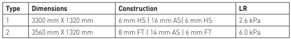
Application to Sample IGUs
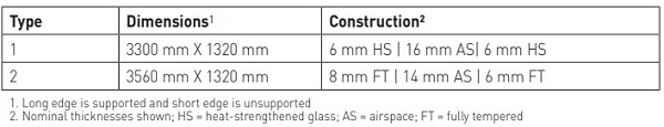
The IGU constructions selected for analysis are shown in Table 1.
Boundary Conditions
Rotational resistance typically provided by the IGU edge sealant between the lites and the spacer is neglected. Due to the presence of the spacer bonded to each lite via the secondary IGU edge sealant, the unsupported edges are not completely unsupported.
Therefore, beam elements are superimposed onto the unsupported edges with a proportioned moment of inertia estimated using a simplistic representation of a spacer cross section.
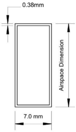
For the sample IGU constructions, it is assumed that the spacer material is aluminum, the wall thickness is approximately 0.38 mm, the width is approximately 7.0 mm, and the height is roughly equal to the airspace thickness (Figure 1).
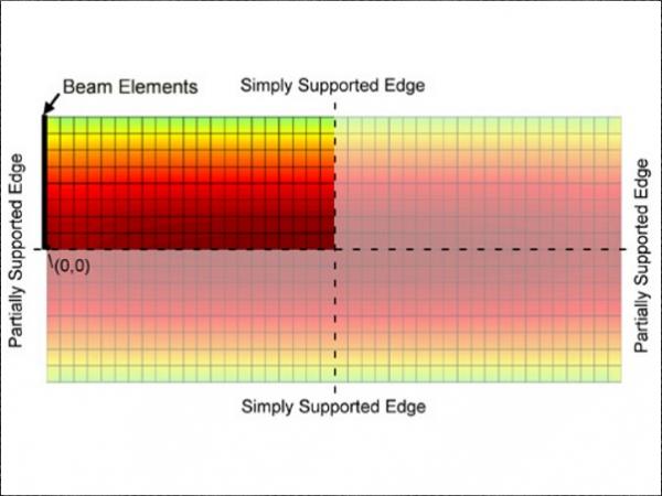
Finite Element Model
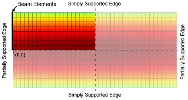
A quarter plate finite element model was used to calculate the deflection and stresses at each node using four node Mindlin-Reissner elements. The partial support provided by the spacer is modeled with superimposed beam elements along the edge of each lite (Figure 2).
The stiffness of these beam elements is determined by calculating the stiffness of the assumed aluminum spacer and roughly proportioning this stiffness to each lite edge in proportion to the stiffness of each lite. Rotational stiffness and shear resistance due to the presence of the secondary IGU edge sealant is neglected. A Young’s Modulus of 7.2 x 10¹⁰ N/ m² and a Poisson’s Ratio of 0.22 were used for the glass material properties.
The proportion of the iteratively applied load carried by each lite in the IGU was determined using a method by Vallabhan and Chou [6] that maintained equilibrium considering the ideal gas law and deformation of each lite. This method accurately accounted for the displaced volumes of the lites when loaded. Each lite was then analyzed individually based on the apportioned load. For the asymmetrical Type 2 unit, the uniform load was applied as a positive and negative pressure to determine the minimum load resistance.
Analytical Results
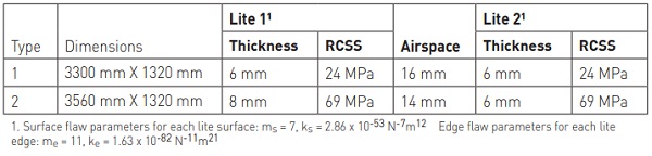
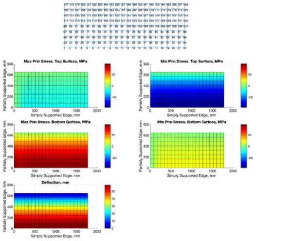
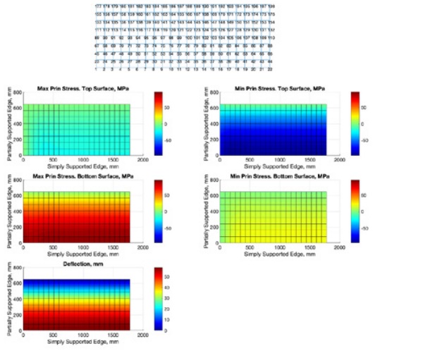
A summary of the model parameters utilized for the two types of IGUs is presented in Table 2. Typical stress and deflection results for the Type 2 IGU lites under the critical positive load case are shown in Figure 3.
Note that predicted deflections are relatively high at approximately L/60 at the full LR. Since this modified analytical procedure assumes the IGU seals are substantially intact, implications for long-term IGU edge seal performance must be considered under actual design and service loads.
In the case of in situ units that only have twosided support due to original installation or loss of support, it is likely that structurally failed edge seals would be evidenced by fogging/condensation within the IGUs. Alternatively, the integrity of the IGU seals could be determined by frost point testing according to ASTM E576-1 [7]. If the units exhibit no visible frost when tested at -30 °C, the hermetic and certainly the structural seal can be assumed to be intact.
Using the modified ASTM methodology described above, the calculated load resistances of the sample IGUs are summarized in Table 3.
Conclusion
Sample rectangular IGUs, both with symmetrical and asymmetrical constructions, supported on only two parallel edges were structurally analyzed using a modified ASTM Analytical Procedure. This procedure considered the additional stiffness provided by spacer along the unsupported IGU edges and it utilized glass flaw parameters for both the glass surfaces and edges in the glass failure prediction model. It provides a means for determining the structural capacity of IGUs that are not completely supported along all four sides.
An inherent assumption is that the IGUs seals remain substantially intact so that load sharing between lites can occur Such a procedure can be used in design and in forensic applications where a loss of support has occurred. The procedure can accommodate various IGU constructions and edge support conditions. Actual glass lite thicknesses and residual compressive surface stresses for heat treated glass can be measured for in situ glass and this data can be utilized in the glass failure prediction model. More advanced modeling of the partial fixity afforded by the IGU edge seal can be incorporated into future models.
Since deflections of IGUs with two-sided support can be significant, long-term IGU edge seal performance and warrantability of such applications should be considered.
References
[1] ASTM, 2016. “Standard Practice for Determining Load Resistance of Glass in Buildings.” ASTM E1300-16, West Conshohocken, Pennsylvania, USA.
[2] Walker and Muir, 1984. “An Investigation of the Bending Strength of Glass Louvre Blades”, Proceedings from 9th Australian Conference on the Mechanics of Structures and Materials, Sydney, Australia.
[3] ASTM, 2018. “Standard Specification for HeatStrengthened and Fully Tempered Flat Glass.” ASTM C1048-18, West Conshohocken, Pennsylvania, USA.
[4] IGMA/NGA, 2018. “Unsupported Edge Conditions of Insulating Glass Units.” Technical Bulletin TB-1800-18, IGMA - Chicago, Illinois, NGA - Vienna, Virginia, USA.
[5] ASTM, 2016. “Standard Specification for Flat Glass.” ASTM C1036-16, West Conshohocken, Pennsylvania, USA.
[6] Vallabhan and Chou, 1986. “Interactive Nonlinear Analysis of Insulating Glass Units.” Journal of Structural Engineering, ASCE - Reston, Virginia, USA.
[7] ASTM, 2014. “Standard Test Method for Frost/Dew Point of Sealed Insulation Glass Units in the Vertical Position.” ASTM E576-14, West Conshohocken, Pennsylvania, USA.