Authors: Gregor Schwind, Fabian von Blücher, Michael Drass & Jens Schneider
Source: Glass Structures & Engineering | https://doi.org/10.1007/s40940-020-00129-3
Abstract
The strength of glass plays an important role in the dimensioning of glass components in the building industry. Here, not only parameters such as support conditions, loading rate, relative humidity etc. play an important role, but the damage by means of scratches also determines the fracture strength of glass. A heat treatment after damaging may have an influence on the resulting glass strength. The correlation between heat treatment temperature, and in particular elevated temperatures up to the glass transition temperature, and fracture stress has been studied by different researchers with several approaches of pre-treatment of specimens and test setups.
This paper methodically presents various preliminary investigations which were carried out within the framework of the pre-treatment of the samples in order to investigate the influence of heat treatment of the pre-damaged samples on the fracture stress. For this purpose, double ring bending tests were performed at room temperature on pre-damaged, heat-treated soda–lime silicate glass specimens. The aim of the investigations is to obtain estimates of the extent to which a heat treatment prior to the strength test influences the fracture strength of soda–lime silicate glass. Parameters like the heat treatment temperature, the dwell time of the samples inside the furnace and the furnace design were considered. The results show that the heat treatment can increase the fracture stress of soda–lime silicate glass as float glass significant due to an assumed healing of the pre-damage during heat treatment.
Introduction and previous research
A major factor determining float glass strength is damage such as scratches or cracks due to the brittle material behavior of glass. Scratches and cracks can be caused by the float glass process itself, the cutting after the float process or also maybe by transport afterwards. With regard to the later dimensioning of glass constructions made of float glass in the building industry, the influence of these damages on the computationally usable material strength is reflected. Due to the fact that the usable bending strength of float glass is low compared to thermally toughened glass, the use of thermally toughened glass sheets is advantageous. However, the toughening process of the glass also increases its price, which causes the material costs of glazing to rise.
If the strength of float glass could be increased by another treatment at lower temperatures, more float glass could possibly be used for glazing. Another application in building industry is fused deposition modelling of glass (Seel et al. 2018a), or simply speaking 3-D printing of glass. Due to the printing process, defects and voids can occur (Seel et al. 2018b) within the additive manufactured component. These flaws represent notches or cracks in the brittle material, which can lead to stress peaks and a comparatively less resistance of the glass. Based on the current state of research, the question has been raised whether the strength of pre-damaged soda–lime silicate glass as float glass can be increased by means of heat treatment, which does not correspond to thermal toughening.
Heat treatments of soda–lime silicate glass as float glass have so far been largely carried out at elevated temperatures (550 to 725 ∘C) by Shinkai et al. (1981), Manns and Brückner (1983), Hrma et al. (1988), Holden and Frechette (1989), Girard et al. (2011), Doquet et al. (2014) and Zaccaria and Overend (2016), although lower temperatures (300 ∘C) have also been used (Wiederhorn 1969). In some investigations, the humidity during heat treatment was regulated within the furnace chamber (Holden and Frechette 1989; Girard et al. 2011). Furthermore, the dwell time of the samples at the temperature varied also in the different publications.
The heat treatment Wiederhorn (1969) used, was 1 h at 300 ∘C to dry the specimens and relieve residual stresses within the glass. The procedure of drying the samples was carried out in order to be able to perform tests in an inert environment (with regard to stress corrosion cracking of glass due to water). Girard et al. (2011) varied the moisture content of the ambient air during heat treatment up to a maximum of 75% RH. Dry ambient conditions were achieved with the aid of noble gas (argon). The heat treatments for crack healing investigations were carried out at temperatures between 550 ∘C (glass transition temperature) and 620 ∘C (softening point of the investigated soda-lime silicate glass). The dwell time of the samples within the furnace and the ambient environment varied between 1 and 28 h in order to be able to investigate the influence of time on crack healing.
Manns and Brückner (1983) used 4 h and 600 ∘C with ambient humid conditions as heat treatment before testing the samples via double ring bending test. They observed that the bending strength of the investigated soda–lime silicate glass as float glass increased. Hrma et al. (1988) also observed crack healing due to the strength test after heat treatment. In their studies they could observe that even a short heat treatment (15 min to 1 h) can influence the resulting fracture strength of soda–lime silicate glass. Holden and Frechette (1989) used a temperature of 550 ∘C with different dwell times and different time spans for the presence of humidity for their heat treatment experiments.
They concluded that a combination of humidity which also has to be present before the heat treatment in combination with an elevated temperature (550 ∘C) may heal cracks as pre-damage in soda–lime silicate glass as float glass. The studies of Holden and Frechette (1989) and Girard et al. (2011) showed, that crack healing occurs at elevated temperatures (550 ∘C). Holden and Frechette (1989) and Girard et al. (2011) observed, that if even slight humidity is present during the heat treatment cracks in soda–lime silicate glass heal better than without humidity.
For the own investigations which are presented in the following the experience in heat treatment given by the past research will be taken into account. Therefore, two temperatures were chosen: lower temperature of 300 ∘C from the studies of Wiederhorn (1969) and elevated temperature of 550 ∘C from other studies (Holden and Frechette 1989; Girard et al. 2011). As material, commercial soda–lime silicate glass is used for the investigations presented here. It is assumed, based on the results of Girard et al. (2011) that the glass transition temperature of this glass is at 550 ∘C. After heat treatment the specimens are tested via double ring bending test at room temperature. Since the furnace design and the experimental set-up for heat treatment, the procedure of pre-damaging and strength test form the basis for a comprehensible experimental procedure, particular importance is given in this publication to describing the used experimental methods in detail.
Theory of the axisymmetric plate
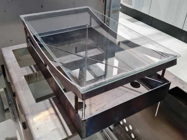
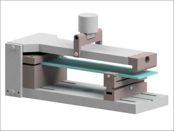
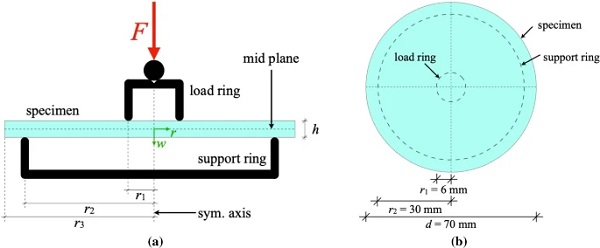
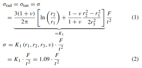
For the calculation of the stresses caused by double ring bending (see Fig. 1a, b) at room temperature, the theory of the axisymmetric plate with consideration of a linear elastic material law may be applied. The deformations that occur in the experiment are relatively small (w/2r₂≪1), which is why effects from geometric nonlinearity can be omitted. In EN 1288-1 (2000) the analytical Eq. (1) is given to calculate the tensile stresses arising in the double ring bending test. In EN 1288-1 (2000) the influence of geometry (r₁, r₂, r₃) and Poisson’s ratio is summarized with the factor K₁. For the test setup R30 according to EN 1288-5 (2000) with consideration of Poisson’s ratio ν = 0.23,K₁ results to 1.09 and Eq. (1) may then be simplified to Eq. (2). The samples used here had a nominal diameter of 70 mm and deviate from the normative specification (d=66 mm). If the diameter of 70 mm and a Poisson’s ratio of 0.22 (assumption) is used to determine K₁, a value of 1.069 results for K₁, which is 2% lower than 1.09.
Experimental investigations
Pre-damaging and storage of the samples
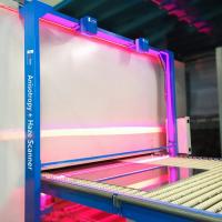
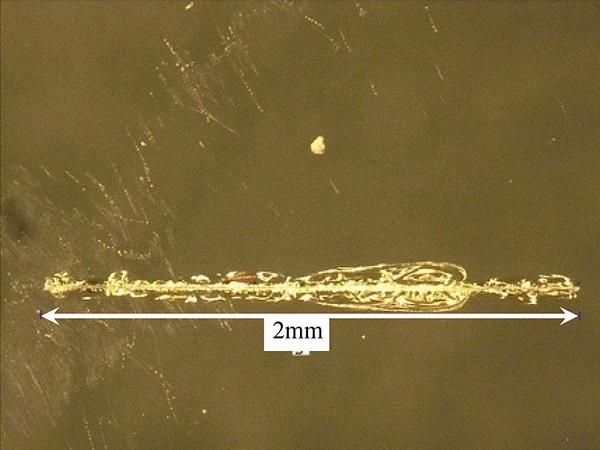
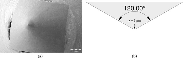
In the first step of pre-treatment, the specimens were pre-damaged with the aid of the Universal Surface Tester (UST, see Fig. 2a). The UST is typically used to scan surfaces for creating surface profiles, indentation and scratching. For the investigations, a conically milled diamond with an angle of 120∘ and a 5 μm radius of curvature at the tip of this cone was used as an indenter (see Fig. 3a, b) to induce a scratch (artificial flaw) on the glass surface (air or tin side of specimen). Ultraviolet light was used to determine the tin side of the sample. The tin ions embedded in the surface by the float process light up brightly under the ultraviolet light. The induced scratch (see Fig. 2b) is intended to represent the influence of surface flaws, which can be caused by flat glass production itself, transport and handling of glass products.
With the presented settings in the list below (Hilcken 2015) the artificial flaw was induced in the glass surface. This type of artificial flaw causes, when performing double ring bending tests, fracture stresses which correspond to the 5% quantile value of the fracture stress of float glass defined in standards [45 MPa according to EN 572-1 (2016)]. The parameters for pre-damaging were selected as follows:
- Indenter: Diamond with an angle of 120∘ and 5μm radius of curvature at the tip
- Force: 500 mN
- Velocity of the indenter: 1 mm/s
- Scratch length: 2 mm
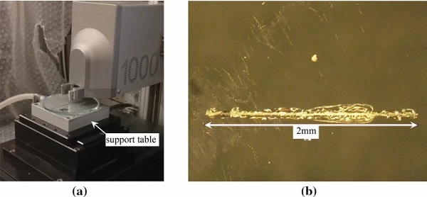
During the initiation of the scratch, the specimen is fixed on the support table (see Fig. 2a) by means of backside vacuum. The surrounding environment during scratching was standard climate (23 ∘C, 50% RH). Finally, the table is moved unidirectionally by 2 mm with a velocity of 1 mm/s. Simultaneously, a force of 500 mN acts on the indenter and thus on the glass surface. The scratch resulting on the specimen’s surface can be seen exemplary in Fig. 2b. The fracture origin of specimens flawed with the presented technique is typically located at this artificial flaw (assuming that the flaw lies within the load ring) when performing double ring bending tests. In the next step of pre-treatment, the specimens were stored at least for one week in a standard climate (23 ∘C, 50% RH) (Hilcken 2015).
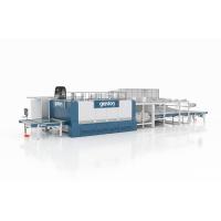
Then, in the last pre-treatment step, the samples were heat treated in a radiation furnace. The heat treatment is intended to study a possible increase of fracture strength by healing the induced scratch. Furthermore, the heat treatment serves to harmonize the material samples in order to eliminate any residual stresses (Shinkai et al. 1981; Wiederhorn 1969) in the glass that may occur as a result of the induced scratch (Assmann et al. 2019). Heat treatment studies were carried out, due to a furnace change and the determined fracture stresses, which are presented in Sects. 3.3 and 3.4.
Experimental test setup for strength tests: double ring bending test at room temperature
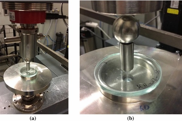
For the determination of the fracture strength of the heat treated soda–lime silicate glass specimens, the double ring bending test was conducted at room temperature and around 50% RH. The specimens used in the studies were circular in shape with a nominal diameter of 70 mm and a nominal thickness of 4 mm or 6 mm. The samples were cut from a flat glass at the factory and the cut edges were coarsely ground. The air or the tin side of the specimens was exposed to tensile stress. A universal testing machine was used for this purpose. Figure 4a, b show the test setup, whereby it should be mentioned that the sample was bonded with a foil on the bending pressure side in order to hold the fragments of the specimen together after fracture.
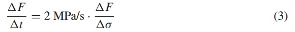
The test setup R30 was used on the basis of EN 1288-5 (2000), whereby the nominal diameter of 70 mm deviates from the standard (d=66 mm). The tests were performed force-controlled with a load rate of 28 N/s for the 4 mm thick specimens (64 N/s for the 6 mm thick specimens). The analytical solution of the double ring bending test at room temperature, see Sect. 2, was used to determine the stress on the glass surface. If force and glass stress are known and a linear elastic material behavior is present (room temperature), the required load rate to obtain a stress rate of 2 MPa/s (EN 1288-5 2000) can easily be calculated by Eq. (3).
Study of heat treatment—Method A
The following sections describe the first study for the heat treatment of the tested material specimens prior to the performed double ring bending tests with the test setup according to Sect. 3.2. The material samples were pre-damaged (flaw on the air side of the specimen) and stored according to Sect. 3.1.
Experimental setup for heat treatment
In this first study—Method A, three test series with ten specimens each with a nominal thickness of 6 mm were prepared. The background for this study was to check how far the heat treatment of the specimen is related to the fracture stress. In order to investigate the fracture stress of the specimens after heat treatment, double ring bending tests were performed at room temperature for all 30 specimens with the test setup presented in Sect. 3.2. The following list gives an overview of the series for the study:
- KN_V1:10 specimens: scratched, stored (23 ∘C, 50% RH)
- KN_V2:10 specimens: scratched, stored (23 ∘C, 50% RH), heat treated with target temperature of 300 ∘C
- KN_V3:10 specimens: scratched, stored (23 ∘C, 50% RH), heat treated with target temperature of 550 ∘C
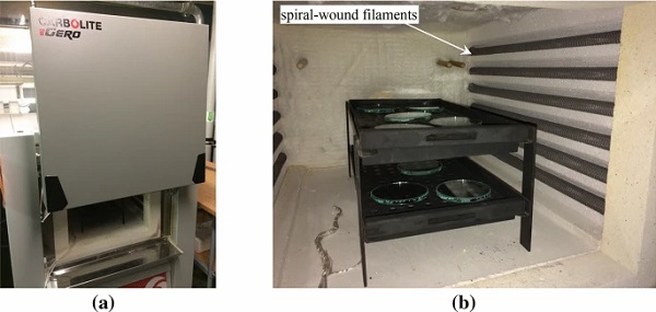
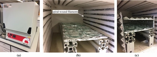
After 30 samples were stored for at least seven days (Hilcken 2015) in standard climate, the samples of the KN_V2 and KN_V3 series were heat treated with the aid of the radiation furnace shown in Fig. 5a, b. Since a series contained ten samples and five specimens could be placed on each grate (see Fig. 5b), one test series was always heat treated together. The initial temperature for the heat treatment was around room temperature. The specimens were placed on the grates with the pre-damaged air side (where the scratch is located) facing upwards. The background was: if the flawed side lies directly on the grate, the handling of the specimens may result in further flaws, which may be more severe than the already applied scratch. One issue was that the humidity inside the furnace chamber could not be recorded during the heat treatment. It is assumed that the relative humidity inside the furnace chamber at the beginning of the heat treatment (room temperature) was around 30 to 40% RH.
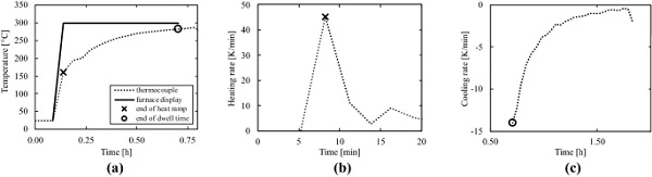
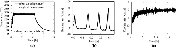
For the heat treatment it was planned, that the samples should be exposed to the respective target temperature for half an hour as scheduled (see solid lines in Figs. 6a, 7a). However, the test showed that, according to the air temperature shown on the display of the furnace (the temperature measured by the furnace itself by means of a permanently installed thermometer), the furnace reached the target temperature (300 ∘C or 550∘ C) after approximately 10 min. After the 10 min of heating, the desired target temperature was maintained for another half an hour. Afterwards the furnace was switched off manually and the furnace cooled down naturally due to its insulation.
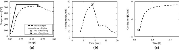
An independent thermocouple (recording frequency of fI ≈ 0.006 Hz) was installed afterwards for a second experiment to check the temperature which was measured by the furnace itself. It should be noted that, during the temperature measurements shown Figs. 6a and 7a just the grate without specimens was inside the furnace chamber, because there were no further test series foreseen at this stage. Due to the missing mass of the glass it may be possible that the heating ramp profile could change. The temperatures measured with the thermocouple are shown in Fig. 6a respectively Fig. 7a (dashed lines). As can be seen from the graphs the target temperature of 300 ∘C respectively of 550 ∘C was nearly reached after approximately half an hour. A maximum temperature of 285 ∘C respectively 525 ∘C was measured.
From the graphs it can be observed, that the samples have not been exposed to the desired dwell time of half an hour at the target temperature. The fact that the furnace has finished heating up after approximately 10 minutes, based on the temperature measured by the furnace itself, can also be analyzed by the heating rates shown in Figs. 6b and 7b. To determine the heating and cooling rates, the slope of the measured temperature curves in Figs. 6a and 7a was calculated. In Figs. 6a, b and 7a, b the X marks the point when heating ramp ended and the dwell time began. The end of the dwell time, when the furnace was switched of manually is marked with a circle in the diagrams in Figs. 6a, c and 7a, c. The heating rate which resulted for the 300 ∘C heat treatment was around 45 K/min (for 550 ∘C heat treatment it was around 55 K/min). It should be noted that the time axes shown in these diagrams represent shortened time segments of Figs. 6a and 7a.
By manually switching off the furnace after half an hour of dwell time (as scheduled) a natural cooling rate resulted, which was initially—14 K/min for the 300 ∘C heat treatment (− 6 K/min for the 550 ∘C heat treatment) and further decreased by temperature decrease. For the sake of illustration: the cooling rates used during thermal toughening reach initial values in the range of multiples of 1000 K/min (Barr 2015), which also decrease strongly and non-linearly. Due to the fact that the specimens cooling down with a comparatively low rate, it is assumed that the samples were not thermally toughened.
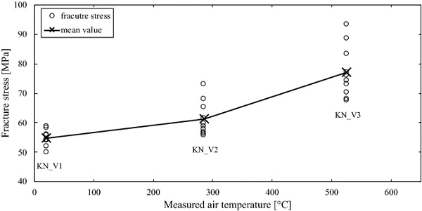
Table 1 Results of the tested series in study—Method A—double ring bending tests at room temperature - Full size table
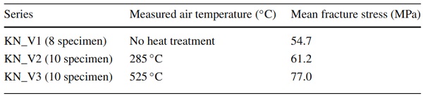
Experimental test results of the fracture stress at room temperature
Figure 8 shows the fracture stresses determined via double ring bending tests in comparison to the temperature during the heat treatment. The fracture stresses were calculated by Eq. (1). The specimens within this study—Method A were tested on the pre-damaged air side. In Table 1 the mean values of the test series are shown, whereby only eight specimens could be used for the test series KN_V1 (one specimen tested with different load rate, another was broken during installation). It can be seen that the heat treatment at measured 525 ∘C results in higher fracture stresses (comparing KN_V1), which can probably be linked to a healing of the induced scratch by elevated temperatures in combination with the moisture in the air of the furnace chamber (Holden and Frechette 1989).
Comparing the mean values of Table 1 it can be seen, that the heat treatment can increase the fracture stress up to 41% (comparing KN_V1 and KN_V3) of the pre-damaged specimen. Even a heat treatment at a lower temperature of 285 ∘C results in higher fracture stresses. An increase of the fracture stress of around 12% (comparing KN_V1 and KN_V2) can be observed. One possibility is that, also at lower temperatures in combination with the moisture in the air inside the furnace chamber crack healing effects occur.
It should be mentioned, that it is assumed that there was no thermal toughening of the specimens (KN_V2 and KN_V3), because the cooling rates in the furnace shown in Sect. 3.3.1 were far below cooling rates normally used in thermal toughening glass (Barr 2015). In addition, the temperatures used in heat treatment presented here were lower than those typically used in thermal toughening (620 ∘C, Barr 2015).
Summary of the preliminary study—Method A
In the study—Method A investigating the influence of heat treatment on the fracture stress of soda–lime silicate glass, it was shown that the heat treatment of pre-damaged soda–lime silicate glass specimens can increase the bending strength extraordinary. In the experiment, where an elevated temperature was present (measured 525 ∘C), an increase of fracture stress of about 41% was observed. The past research of Holden and Frechette (1989) and Girard et al. (2011) could also observe crack healing at these elevated temperatures.
In the second case, where the temperature was lower (around 285 ∘C) also an increase of fracture stress could be observed, which does not seem logical, because the temperature for crack healing was too low (compared to Holden and Frechette 1989; Girard et al. 2011). For both experiments presented here it could also be shown, that even a very short dwell time at low or elevated temperatures may increase the fracture stress of the soda–lime silicate glass as float glass. Since the furnace for heat treatment of the material samples was changed in the further procedure, further studies of heat treatment (Method B) were carried out with a different furnace. These studies are presented in the following paragraphs.
Study of heat treatment—Method B
In the second study—Method B, a different radiation furnace (not identical in construction see Figs. 5, 9) was used, so further investigations on heat treatment were carried out. As in the first study—Method A, the specimens used in this study were pre-damaged using the method described in Sect. 3.1 and stored for at least seven days in standard climate. The following list gives an overview of the series for this study:
- KN_V4: 8 specimens: scratched, stored (23 ∘C, 50% RH), heat treated with target temperature of 300 ∘C with radiation shielding
- KN_V5: 8 specimens: scratched, stored (23 ∘C, 50% RH), heat treated with target temperature of 300 ∘C without radiation shielding
Experimental setup for heat treatment (with and without radiation shielding)
Figure 9a shows the used radiation furnace for the second study— Method B. The target temperature at which the heat treatment was scheduled had an upper limit of 300 ∘C in accordance to Wiederhorn (1969). To do so, the heating rate of the furnace was set to 10 K/min at the furnace control so that the air temperature will reach 300 ∘C after 0.5 h. The temperature of 300 ∘C was then kept almost constant for 4 h. After 4 h the furnace cooled down naturally due to its insulation. When comparing the walls of the two furnaces (Figs. 5b, 9b), it can be seen that the arrangement of the spiral-wound filaments within the chamber is different.
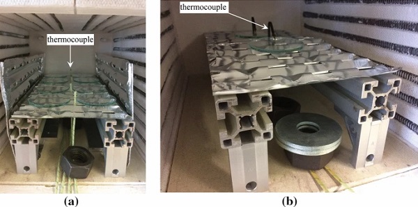
In the first furnace, the filaments are located on the left and right walls of the furnace chamber. These filaments hang freely in front of the wall (see Fig. 5b). In the second furnace, the filaments are located on the side walls and the top of the furnace chamber (see Fig. 9b). Here, the filaments are embedded in a temperature-resistant insulating material. The different design of the furnace chamber is expected to result in a different temperature profile (measurements). Due to the grate size of the furnace only eight material samples could be placed on the grate. Different temperature measurements by use of four type K thermocouples (see Fig. 10a) were carried out:
- Air temperature measurement without radiation shielding, Sect. 3.4.2
- Specimen surface temperature measurement without radiation shielding, Sect. 3.4.3
- Air temperature measurement with radiation shielding, Sect. 3.4.4
The thermocouples were inserted through the grate from below and recorded the air/surface temperature with a frequency of fII = 0.1 Hz near the specimen or on its surface. In order to check which temperature would be reached on the glass surface without radiation shielding, another measurement was carried out using two material samples. To do so thermocouples were bent onto the glass surface so that there was direct contact between thermocouple and glass surface (see Fig. 10b). The initial temperature for the heat treatment was around room temperature. The samples were placed on the grate with the pre-damaged tin side (where the scratch is) facing upwards according to Sect. 3.3.1. One issue is that the humidity inside the furnace chamber could not be recorded during the heat treatment. It is assumed that the humidity inside the furnace chamber at the beginning was around 30 to 40% RH.
Heat treatment: without radiation shielding
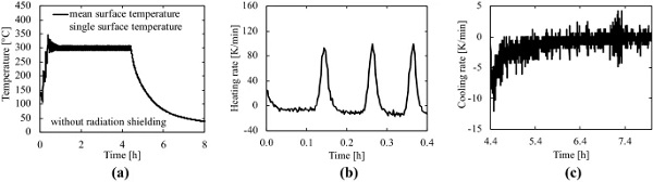
The specimens were placed on the grate without protection against radiation (see Fig. 9b). The air temperature within the furnace chamber near the specimens was measured with four thermocouples (see Fig. 10a). It should be mentioned that the aluminum sheets to the left and right in Fig. 10a were not present. From the four measurements the mean value of air temperature, which is shown in Fig. 11a, was calculated.
The corresponding heating and cooling rates, which are shown in Fig. 11b, c, were calculated with the recorded time and mean temperature. It should be noted that the time axes in Fig. 11b, c represent sections of the axis from Fig. 11a. As can be seen from Fig. 11b, the target of heating the furnace at 10 K/min could not be achieved due to a non-optimized (optimization regarding electric power) furnace control. After half an hour, the heating ramp ended as scheduled at a measured mean air temperature of around 280 ∘C. After 4 h dwell time at 300 ∘C target temperature, the furnace switched itself off and cooled down naturally.
Heat treatment: without radiation shielding—measured surface temperature
In order to determine the temperature that occurs on the glass surface of the specimens during heat treatment, another temperature measurement was carried out on two specimens. For this purpose, thermocouples were bent onto the glass surface of the samples so that the thermocouples were in direct contact to the surface (see Fig. 10b). The two specimens were used from the KN_V5 series, so that finally only six specimens (see Table 2) were available for evaluation of this series. If Figs. 11 and 12 are compared with each other, it can be seen that the qualitative trends are quite similar. However, at the maximum temperature measured during the heating ramp, it can be seen that the air temperature reaches a maximum value of approximately 330 ∘C (Fig. 11a—single air temperature) and the surface temperature a value of approximately 354 ∘C (Fig. 12a—single surface temperature).
A difference of 24 K (temperature overshoot) between air and surface temperature and a difference of 54 K between target and surface temperature can be observed. These differences show the occurrence of higher surface temperatures during the heating ramp due to a non-optimized furnace control. A second observation shows that, after the thermal equilibrium was reached (around 1 h after the beginning of the experiment), the surface temperature reached the target temperature of 300 ∘C. A result of the observations is that the radiant energy emitted by the spiral-wound filaments generates a comparatively higher surface temperature than the air temperature.
In order to exclude the temperature overshoot during the heating ramp, as shown in Fig. 9c and as already mentioned before, a radiation shielding, which was built using aluminum sheets (hereinafter also called aluminum enclosure), was provided inside the furnace. This created a chamber within the furnace which massively disturbs the convection within the furnace chamber, which otherwise would have been free to develop. Due to the installation of the aluminum enclosure inside the furnace chamber, the experimental setup for heat treatment had changed and a further measurement of temperature was performed.
Heat treatment: with radiation shielding
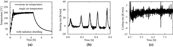
The specimens were placed on the grate protected against thermal radiation (see Fig. 9c) with the help of the aluminum enclosure. The aluminum sheets were placed around the specimens and build a radiation shielded room within the furnace chamber. The air temperature within this room was measured with four thermocouples near the specimens (see Fig. 10a). For clarification, the upper cover of the aluminum enclosure, which is not shown in Fig. 10a, was also present during this air temperature measurement. From these four measurements the mean value, which is shown in Fig. 13a, was calculated. The corresponding heating and cooling rates, which are shown in Fig. 13b, c, were calculated with the recorded time and mean temperature. In Fig. 13a it can be observed that due to the disturbed convection inside the furnace chamber it took around three hours (from the beginning of the experiment) when the thermal equilibrium was reached within the aluminum enclosure.
This can be observed considering the mean air temperature curve which slightly increases (curve between 0.5 and 3 h in Fig. 13a) after the heating ramp ended. The specimens that were heat treated with the aluminum enclosure thus underwent a temperature of approximately 200 ∘C. There is a difference of 100 K (comparing surface temperature measured in Sect. 3.4.3 and air temperature measured here) between the heat treatment with radiation shielding and without radiation shielding. Considering Fig. 13a, a smaller but existing temperature overshoot is shown in comparison to the previous air temperature measurements. Furthermore, it should be mentioned that, the installation of the thermocouples did not allow the furnace door to be closed completely, resulting in a small gap which allows a comparatively higher air exchange than when the furnace door is completely closed. It is assumed that a slight exchange of air is possible even when the oven door is closed.
If the heating rates shown in Figs. 11b and 13b are compared, the effect of radiation shielding also becomes visible. The heating rates in the single heating periods when the furnace is heated up in the beginning of the heat treatment reach only half the values with radiation shielding as without radiation shielding. When considering the cooling rates, the difference is smaller and does not play as an important role as the heating rate difference.
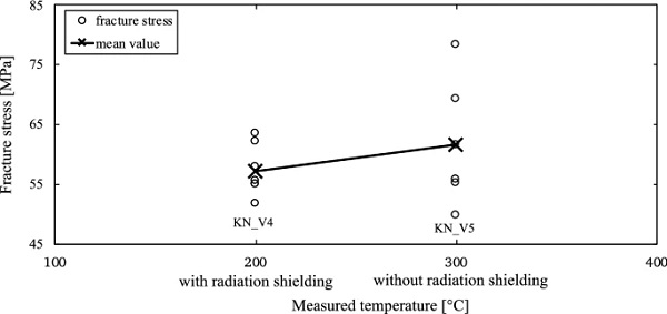
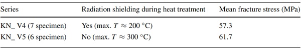
Table 2 Results of the tested series in study—Method B—double ring bending tests at room temperature - Full size table
Experimental test results of the fracture stress at room temperature
In order to determine to what extent, the heat treatment of the second study—Method B affects the fracture stress of the material specimens, double ring bending tests were carried out at room temperature as in the first study—Method A. Figure 14 shows the fracture stresses versus the used technique (and subsequent temperature) in heat treatment. The fracture stresses were calculated by Eq. (1). The specimens within this study—Method B were tested on the pre-damaged tin side. In Table 2 the mean values of the test series are shown. The test series KN_V4 and KN_5 consist of eight samples each which were subjected to heat treatment. For series KN_V4, however, one specimen broke when installed in the test apparatus, so only seven specimens were evaluated. For series KN_V5, two samples were subjected to heat treatment twice to measure the temperature on the glass surface (see Sect. 3.4.3), so only six specimens were analyzed.
When comparing the mean values of the fracture stress, it can be seen that, without the aluminum enclosure during the heat treatment, approximately 8% higher fracture stresses result comparing KN_V4 and KN_V5, which is possibly related to the fact, that a higher temperature (around 300 ∘C, see surface temperature measurement Sect. 3.4.3) was present during heat treatment. Comparing the mean values of fracture stress of the test series KN_V1 and KN_V5 an increase of 13% can obtained. If the mean value of KN_ V4 (57.3 MPa) is compared with the mean value of the test series KN_V1 (untreated specimens, 54.7 MPa) a very slight increase of 5% of fracture stress can be obtained. Based on the small sample size, however, it can be assumed that the scatter of the fracture stress is relatively large. It cannot be concluded from the small amount of data whether crack healing effects have already taken place at 200 ∘C heat treatment.
Summary of the study—Method B
In the second study—Method B several observations could be made. The first both measurements showed that due to the furnace design (radiation furnace) and the furnace control of heating it is possible that the surface temperature can exceed the target temperature (300 ∘C for Method B) set in the furnace control unit. A difference of 54 K between the surface and the target temperature could be observed. The second observation is that the air temperature and the surface temperature reached a difference of 24 K. These experiments have shown that there can occur a temperature overshoot on the glass surface. How large this overshoot will be, when using elevated temperatures (550 ∘C) cannot be stated at this time. To overcome this temperature overshoot, the aluminum enclosure was introduced.
The use of the aluminum enclosure during the measurements showed, that it has an influence (lower temperature than target temperature) on the resulting temperature profile. But still a relative overshoot during the heating ramp is present, which indicates that amount of electric power or the heating ramp rate (10 K/min) which can be regulated by the furnace control unit need to be lowered. From the results of the third measurement (heat treatment with radiation shielding) it could also be observed that a longer time span is needed for reaching the thermal equilibrium within the furnace. The time needed for thermal equilibrium within the first both measurements was at around 1 h (from the beginning of the experiment), in the third experiment it was reached after approximately 3 h. How the time needed for thermal equilibrium will change for other temperatures cannot be estimated at this time, because several experiments including measurements have to be conducted therefore.
In the subsequent determination of the fracture strengths, the influence of the different temperatures also became apparent, as in Method A. The samples that underwent a heat treatment at 300 ∘C (KN_V5) yielded on average higher fracture stresses than the samples that underwent a heat treatment at 200 ∘C (KN_V4, 8% of increase) or that were untreated (KN_V1, 13% of increase).
When comparing the mean values of the fracture stresses between KN_V1 (untreated) and KN_V4 (200 ∘C) nearly the same mean values of fracture stresses result, so it is possible that no crack healing during heat treatment occurred. At this stage of research, it is not possible to make a statistically reliable statement as to whether heat treatment at 200 ∘C results in higher fracture strengths, because the test series contained too less specimens.
Conclusions
The experimental investigations carried out so far showed that the heat treatment of pre-damaged soda–lime silicate glass as float glass can increase the fracture strength of the glass. In the study—Method A, where especially an elevated temperature of around 525 ∘C for a short time period (lower than 15 min) was used, an increase of the mean value of the fracture stress of around 41% could be observed comparing mean values of fracture stress of KN_V1 and KN_V3. Also, during heat treatment at lower temperatures (around 300 ∘C, both Method A and Method B) without radiation shielding, an increase of the fracture stress of the glass from approximately 12% (Method A) to 13% (Method B) could be observed, comparing with the untreated specimens of KN_V1.
It is not yet possible to make statistically sound statements on the relationship between heat treatment temperature and fracture strength at the current state of research, as the sample size of the test series with six to ten samples was very small. Nevertheless, the investigations have shown that the heat treatment can have an influence on the resulting fracture strength of the pre-damaged soda–lime silicate glass as float glass, which can be linked to a healing of the induced scratch. It could also be shown by surface temperature measurements (without radiation shielding) that the surface temperature of the glass samples is higher than the air temperature inside the furnace chamber, which can be explained by the furnace design (radiation furnace).
At the current state of the investigations it is not yet possible to predict how large the temperature differences between air and surface temperature can become if elevated temperatures (e.g. 550 ∘C) are used for heat treatment. It could also be shown that the overshoot of air temperature during the heating ramp also occurs (relatively) when the aluminum enclosure is applied. Another observation which was made is, that the time needed for thermal equilibrium when using a radiation shielding increases from 1 h to around 3 h (from the beginning of the heat treatment at 300 ∘C target temperature), which results from the disturbed free convection.
The measurements of air and surface temperature have also shown that the natural cooling of the furnace leads to cooling rates that are far below the rates used in the thermal toughening process. It is therefore obvious that the material samples were not thermally prestressed by the heat treatment prior to the double ring bending test, which might have been interpreted as a result of higher fracture stresses.
Outlook
For future research concerning crack healing of pre-damaged soda–lime silicate glass as float glass as a result of heat treatment, various aspects have arisen on the basis of the present work which will be considered for future experiments. Past research has already shown that, heat treatment can be used to increase the resulting fracture strength of glass, although the approaches of the various sources differ from each other and also differ from the method of pre-damage and strength determination presented here. The literature (Holden and Frechette 1989; Girard et al. 2011) has shown that especially the moisture in combination with elevated temperatures are the driving factors for crack healing in soda–lime silicate glass. At the current state it was not possible to measure the moisture inside the furnace chamber. For future experiments the moisture in the surrounding environment will be measured, that afterwards the mass of water which is solved in the air within the furnace chamber can be calculated.
A further aim for future studies is to improve the heating ramp in such a way that a temperature overshoot does not occur. Therefore, the heating ramp defined in the furnace control unit of 10 K/min will be reduced to a lower value. It may then be possible to remove the workaround of the aluminum enclosure. Further temperature measurements will be conducted afterwards to ensure that the air temperature and the surface temperature are nearly equal.
Further experiments on heat treatment at elevated temperatures (500–550 ∘C) will be carried out in order to be able to make statistically sound statements on the influence of heat treatment at elevated temperatures on the fracture strength of soda–lime silicate glass with the aid of a larger sample size and Weibull analysis. Another objective for future experiments is that heat treatment experiments at lower temperatures beneath 500 ∘C will be performed, because the results presented here indicate that already at lower temperatures (300 ∘C) an increase of the fracture stress can occur. For the different heat treatment temperatures it is also foreseen that different dwell times of the specimens within the furnace at given temperature will be studied.
Acknowledgements
Open Access funding provided by Projekt DEAL. Special thanks go to the Institute of Materials Technology in Darmstadt, which provided the experimental apparatus for the investigations presented in Method A. Furthermore, we would like to thank the Deutsche Forschungsgemeinschaft (DFG, German Research Foundation)—Projektnummer 399287305, which provided financial support for this research project.
Author information
Authors and Affiliations
Institute of Structural Mechanics and Design, Technical University of Darmstadt, Darmstadt, Germany
Gregor Schwind, Michael Drass & Jens Schneider
Institute of Materials Technology, Technical University of Darmstadt, Grafenstraße 2, 64283 Darmstadt, Germany
Fabian von Blücher
Corresponding author
Correspondence to Gregor Schwind.