This paper was first presented at GPD 2023.
Link to the full GPD 2023 conference book: https://www.gpd.fi/GPD2023_proceedings_book/

Authors:
- Francis Serruys - Saint-Gobain
- Dr. Andreas Kasper - Diplomchemiker - Consultant
- John Colvin - JCGC Ltd
- Frank Rubbert - Saint-Gobain
Abstract
Spontaneous breakage of fully tempered (FT) glass in facades is under control today when the heat soak process according to EN 14179-1 (2006/2016) is rigorously carried out. However, nickel sulphide (NiS) breakages are not only observed in FT glass but also in heat strengthened (HS) glass.
HS glass has a lower surface compression and thus a lower central tensile stress when compared to FT glass. Consequently bigger NiS inclusions are required to initiate a crack, as crack initiation is determined by the inclusion’s size in combination with the surrounding stress field.
The critical diameter “Dc” to cause spontaneous fracture of glass is determined. A good correlation is found with the diameter of reported NiS inclusions causing breakages on a building facade. Knowing the distribution and the diameter range of NiS inclusions in float glass, a breakage probability, on a statistical basis, of 1 breakage in (1,100 ± 200) tonnes of HS glass can be estimated.
More data of broken HS glass due to NiS inclusions is required to confirm the breakage probability, which in reality might be much lower. Due to this low breakage probability it is not industry practice to carry out the heat soak process. Moreover HS glass does not satisfy code requirements for safety glazing. Therefore HS glass is most often used in the form of laminated safety glass. If a NiS inclusion would cause a breakage of a laminated HS glass, it would stay in place due to its specific fragmentation as required by EN 1863.
Introduction
In 1961 Ballantyne (1961) was the first to describe the mechanism whereby NiS causes FT glass to break. [1] It took till the 1970s to come up with a heat treatment, later on called the heat soak test (HST), to eliminate critical NiS inclusions trying to avoid spontaneous breakage of FT glass. The German standard DIN 18516, derived from this test, fixed a holding time of eight hours at constant oven temperature, but it was, however, very imprecise and could easily be misinterpreted. Therefore, in the mid-1990s CEN started to work on a new heat soaked FT glass product standard, the result being EN 14179-1 Glass in Building - Heat-Soaked Thermally Toughened Soda Lime Silicate Safety Glass.
Since the beginning the focus of R&D has been on understanding and reducing the residual risk of spontaneous breakages due to NiS inclusions in FT glass. Only on rare occasions were spontaneous breakages of HS glass mentioned or dealt with. [2]
The knowledge gathered on the properties of NiS inclusions, their distribution and dimensions in soda-lime silicate glass is used to make an estimation of the breakage probability of NiS inclusions in HS glass. Nickel sulphide is a complex material, which undergoes a phase change (a change in crystalline structure) at a transformation temperature between 282 °C and 379 °C, depending on the precise combination of nickel and sulphur (called the stoichiometry) [3]. The mechanism which causes failure in the façade is due to the phase change being accompanied by a volume change. The α phase, which is stable above the transformation temperature, has a smaller volume than the β phase, which is stable below the transformation temperature.
The tempering (toughening) process in glass requires the glass to be heated to around 620 °C, which softens the glass, followed by rapid cooling. Any nickel sulphide in the glass is converted to the α-phase at the high temperature, but the rapid cooling does not allow time for the conversion back to the β-phase. The nickel sulphide is thus "frozen" into the FT glass in an unstable form.
Over a period of time the α-phase slowly converts back to the β-phase, the conversion being accompanied by an increase in volume of 2.55 % at ambient temperature [4]. If a NiS inclusion is sufficiently large and is in the central (tensile stress) zone of the FT glass [5], then the expansion caused by the phase transformation can exert sufficient excess stress to cause a crack to propagate, leading to disintegration of the pane.
![Figure 1 Composition range of nickel sulphide inclusions eventually leading to glass breakage. Dotted (–o–o–) curve: estimated probability of occurrence, based on LAFFITTE’s papers (limit value 1.06 for occurrence in glass) [10] [11], and YOUSFI’s papers (limit value 1.047 for breakages) [12] [13].](/sites/default/files/inline-images/Fig1_331.jpg)
1. Properties of nickel sulphide inclusions
Kasper (2018 / 2020) and Kasper et al. (2018) wrote a series of four articles where the properties of NiS inclusions, their distribution in float glass, a statistical evaluation of field breakage records and consequences for residual breakage probability are dealt with in detail. [5] [6] [7] [8] These papers were presented at the Glass Performance Days 2019. [9] The key points are highlighted in this article for better understanding the method used to estimate the breakage probability of NiS inclusions in HS glass.
1.1 Composition of nickel-sulphide inclusions
Only NiS inclusions containing (at least partly) the 1:1 composition and those with a small sulphur excess are of interest, because this chemical compound is the only one to be subject to slow α to β phase transformation at ambient temperature. According to the nickelsulphur phase diagram, this composition can only form if xliquid is in the range 0.89 < xliquid < 1.06. Then the solely interesting and solely observed phases in the crystalline hightemperature NiS inclusions are Ni₉S₈ and NiSₓ where xsolid is in the range 1 ≤ xsolid < 1.06. The composition Ni₃S₄ is occasionally observed in the transformed β phase NiS inclusions as a subsequent product of slow diffusional transformation.
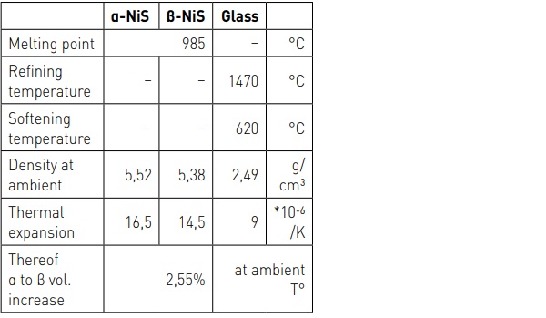
1.2 Nickel sulphide properties
1.3 Size and size distribution
A dataset of 140 NiS inclusions identified in annealed glass were analysed. [5] The following observations were made:
- Small inclusions (c. < 140 μm) are more frequent than big ones.
- Very small inclusions (c. < 50 μm) are rare.
- Inclusions are found “everywhere” in the glass.
- The signature of a gravitational settling is visible analysing the position of the NiS inclusions in the glass section.
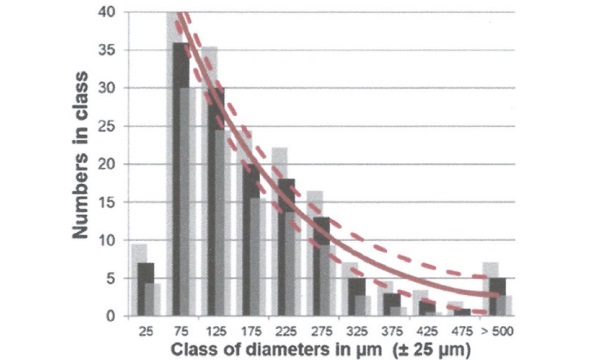
All superficial NiS inclusions are located in the bath side; none in the atmospheric side. Figure 2 shows the histogram evaluation of the dataset using classes of 50 μm. With exception of the classes of the smallest (< 50 μm) [5] and maybe the biggest (> 500 μm) [6] inclusions, all counted numbers per class seem to match with a decaying exponential curve. Physical modelling shows that only medium size NiS inclusions arrive in the final glass whereas the smallest decompose quickly (or remain undetected), the biggest go to the bottom (gravitational settling), and a nonnegligible fraction decomposes spontaneously under its own vapour pressure.
2. Fracture Mechanics
The inclusion’s size and the surrounding stress field play the deciding roles for crack initiation. In other words, the position of a nickel sulphide inclusion is not really the deciding factor on breakage occurrence; the predominant factors are the local tensile stress combined with the size of the NiS inclusion.
2.1 Heat strengthening
Heat strengthened soda lime silicate glass is defined in the European product standard EN 1863-1:2011 as glass within which a permanent surface compressive stress, additionally to the basic mechanical strength, has been induced by a controlled heating and cooling process in order to give it increased resistance to mechanical and thermal stress and prescribed fracture characteristics. [14] Although the minimum value for the mechanical strength is defined as 70 N/mm², EN 1863-1:2011 clearly states that the manufacturer shall ensure that the fragmentation always satisfies the requirements of the standard.
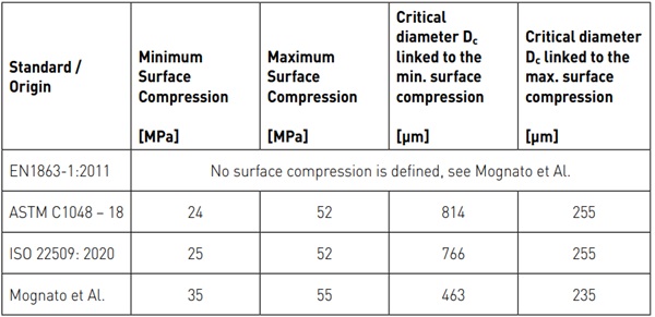
Mognato et Al. (2017) demonstrated that the minimum surface compression of heat strengthened glass should be 35 N/mm² in order to reach the characteristic bending strength of 70 N/mm². [15] However a surface compression of 55 N/mm² is confirmed as upper limit for still having a correct fragmentation. Based on this data the acceptable range of surface compression meeting the requirements of EN 1863-1:2011 should be 35 N/mm² ≤ σc ≤ 55 N/mm². As the tensile stress at the glass’ midline is half of the surface stress, the maximum tensile stress σ0 can be set at 27.5 N/mm².
In opposition to the EN 1863-2011, other product standards are defining a surface compression, e.g. ASTM C1048 – 18 defines that heat strengthened glass with a thickness of 6 mm and less shall have a surface compression between 24 to 52 MPa (i.e. 12 N/ mm² to 26 N/mm² tensile stress in the middle). [16]
ISO 22509:2020 specifies that a minimum value for surface pre-stress of 25 MPa is needed. Additionally, the maximum value for surface pre-stress should not exceed 52 MPa to achieve the specified fragmentation behaviour. [17]
2.2 Critical size of the nickel sulphide inclusion
According to Swain (1981) the critical radius of an inclusion with internal pressure P₀ in a tensile stress of σ₀ for spontaneous fracture is given by the equation: [18]
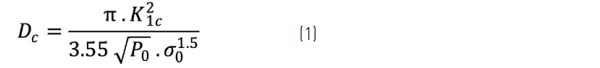
Where:
- Dc critical diameter of the inclusion required to cause breakage [m]
- K1c stress intensity factor
- P₀ surface pressure exerted by the inclusion due to the α to β phase change and also to the different coefficients of thermal expansion between NiS and glass
- σ₀ (maximum) tensile stress in the glass [MPa]
Special attention shall be paid to the parameters P₀ and K1C used by Swain:
I. Surface pressure P₀
a) The density difference between α and β phase is supposed to be 4%. Since then, it has been proven that the volumetric expansion is 2.55% and not 4%. [4]
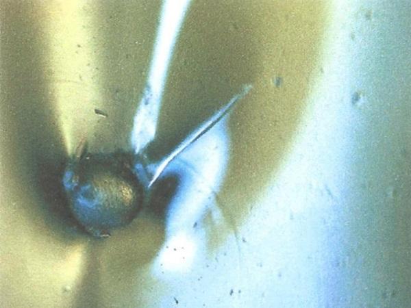
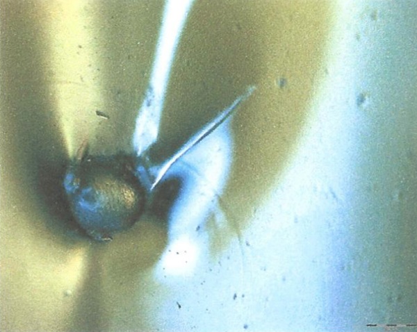
b) The difference in thermal expansion coefficients of glass and nickel sulphide is supposed to cause a negative pressure onto the glass during cooling. However, figure 3 shows that there’s no cohesion between glass and NiS inclusions. The lack of cohesion between glass and nickel sulphide is related to the non-wettability and insolubility of nickel sulphide in the glass (melt). This fact is important because if there is no cohesion the stress situation around the (untransformed) inclusion resembles that of a (notched) bubble, but not to that of a “normal” (silicate, silicon, other interlocked) inclusion. It is also important because an (untransformed) NiS inclusion that is smaller than its surrounding bubble does not exert force onto the glass.
c) The strength of glass surface surrounding the nickel sulphide, is affected by the notched nature of the surface of these inclusions. The superficial wrinkles are not in-line with Griffith’s assumptions on the weakening of the glass strength due to surface cracks. But, even if the “tip” of the “crack” is rounded, the additional stress concentration due to such a structure is not negligible.
d) Finally, the combination of all these means that a transformation ratio at ambient temperature up to 55% is needed before the first breakages appear. [6]
Therefore, the surface pressure P₀ is lower than 615 MPa, as determined by Swain. Calculating P₀ using the new data gives a value of 266 MPa at ambient temperature (i.e. for facades).
II. Stress intensity factor K1C
K1C is commonly measured on glass using macroscopic methods. These methods reveal the strength of glass under controlled atmospheric conditions, i.e. such as under the influence of water vapour. However, at ambient temperature the gap between the NiS inclusion and the surrounding glass might really be a vacuum. This means that K1C increases. For the time being a stress intensity factor K1C of 0.79 has been estimated for the situation in facades (at ambient temperature).
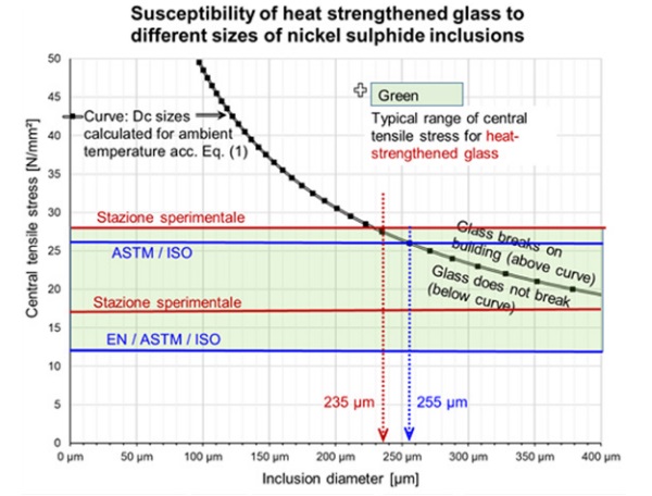
Table 2 shows the minimum and maximum surface compression as specified in official standards and the corresponding critical diameter Dc. The surface compression measured by Mognato et Al. (2017) is also given with the corresponding critical diameter Dc. As the threshold of inclusions in float glass can be set at 500 µm due to the gravitational effect in the glass melt, it is unlikely to find critical NiS inclusions for a tensile stress σ₀ < 17 N/ mm² or a surface compression < 33 N/mm². In figure 4 the curve Dc calculated for ambient temperatures (i.e. facade application) is drawn as well as the typical range of central tensile stress for HS glass.
Below the curve, the inclusion’s size is supposedly too small to make the glass break. Above the curve, breakage might be caused with increasing probability.
Typically, NiS inclusions having a diameter of more than 235 µm are required to break HS glass produced in accordance with the EN 1863-1:2011. This corresponds to records collected of the diameters of NiS inclusions found at the origins of glass breakages on buildings.
3. Breakage probability
Knowing the distribution and the diameter range of NiS inclusions in float glass a breakage probability can be estimated. [7] Only about 24% of the NiS inclusions found in float glass are bigger than 235 µm. Breakages caused in HS glass by smaller inclusions are rare and can be disregarded.
Because of the lower stress regime, it can be estimated from the diagram above, in combination with their estimated frequency of occurrence, that in comparison with FT glass, 31% of the NiS inclusions would be critical even under heat soak test conditions.
Finally, Kasper (2018) came to the conclusion that only 10% of the breakages observed in the heat soak test would happen on a building (i.e. only 10% of the critical NiS inclusions in the heat soak test are relevant for the building). Consequently, a qualified but conservative breakage probability of 1 breakage in (1,100 ± 200) tonnes can be estimated for HS glass. This is still lower than the level of residual risk stated in the heat soaked toughened glass standard EN 14179-1:2016, i.e. the risk of spontaneous breakage of heat soaked thermally toughened soda lime silicate safety glass, on a statistical basis, due to the presence of critical NiS inclusions, is no more than one breakage per 400 tonnes of heat soaked thermally toughened soda lime silicate safety glass.
Recent studies by Kasper (2018) and Kasper et Al. (2018; 2020) estimate the residual risk of only 1 breakage in 10,000 tonnes of really heat soak tested glass.
4. Interpretation of the breakage probability
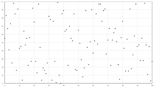
Random events occur in clusters, so in any particular quantity of glass there may be more or less critical NiS inclusions than might be expected. To give a feel for how randomness affects the numbers of incidents, the diagram in figure 5 shows 100 points randomly distributed (using a computer random number generator) in 100 squares, averaging 1 per square. There is one square with a cluster of 4 points and many squares have none. This is not an atypical event, but has given rise to the idea of NiS inclusions occurring in batches. [3]
The breakage probability has to be interpreted in this way, i.e. it is a statistical approach of an extremely large amount of data gathered over several decades. Therefore, it is not possible to claim that no breakages or a maximum of one breakage will occur because the quantity of glass used for the building is less than (1,100 ± 200) tonnes of HS glass.
Moreover, other types of inclusions may cause breakages which are not considered in this study. [6]
Conclusion
Although the residual risk of heat soak tested thermally toughened safety glass is very low, HS glass is often preferred under the assumption that it does not suffer from spontaneous breakages due to NiS inclusions. This is definitely untrue. The lower tensile stress in the centre of the HS glass makes the glass much less vulnerable to spontaneous breakages compared with FT (not heat soaked tested) glass. However, a conservative breakage probability of 1 breakage in 1,100 ± 200 tonnes is estimated for HS glass. More data of broken HS glass due to NiS inclusions found on facades is required to confirm the breakage probability which in reality might be much lower.
HS glass is not a safety glass and is most often processed into laminated safety glass. If a NiS inclusion would cause a breakage of a laminated HS glass, it would stay in place due to its specific fragmentation as required by EN 1863. Hence the low breakage probability, in combination with its usage as laminated HS glass, means the heat soak test is usually not done.
References
[1] Ballantyne E.R.: Report 061-5: CSIRO, Division of Building Research, Melbourne: 1961
[2] Bordeaux F., Kasper A.: Reliable and shorter heat soak test to avoid spontaneous fracture of heat strengthened and tempered glasses. In: Conference proceedings of the “Glass Processing Days” in Tampere, Finland, pp. 85-89 (1997)
[3] Colvin, J.: Technical Note 20 – Nickel Sulphide Inclusions(2013 – revised version: 2016)
[4] Groenvold, F., Stoelen, S.: Heat capacity and thermodynamic properties of millerite from ... Thermochimica Acta 266 (1995) pp.213-229
[5] Kasper A., Pyeonglae N., Yuan Z.: Spontaneous cracking of thermally toughened safety glass. Part two: nickel sulphide inclusions identified in annealed glass. Glass Struct. Eng. (2018b). https://doi.org/10.1007/s40940-018-00092-0
[6] Kasper A.: Spontaneous cracking of thermally toughened safety glass. Part one: properties of nickel sulphide inclusions. Glass Struct. Eng. (2018a). https://doi.org/10.1007/s40940-018-0083-8
[7] Kasper A.: Spontaneous cracking of thermally toughened safety glass. Part three: statistic evaluation of field breakage records and consequences for residual breakage probability. Glass Struct. Eng. (2018c). https://doi.org/10.1007/s40940-018-00093-z
[8] Kasper A., Rubbert F.: Spontaneous cracking of thermally toughened safety glass. Part four: a case study of isothermal breakages in a building, and conclusions thereof for the heat soak test. Glass Struct. Eng. (2020). https://doi.org/10.1007/s40940-020-00118-6
[9] Kasper A.: Spontaneous Breakages of Toughened Glass: The H.S.T. is better than Presumed. In: Conference proceedings of the “Glass Performance Days” in Tampere, Finland, pp. 205-211 (2019)
[10] Laffitte, M.: Origine des variations de composition du NiS hexagonal. C. R. Acad. Sci. 243, 58–61 (1956)
[11] Laffitte, M., Crousier, J.-P.: Limites du domaine de stabilité du NiS hexagonal. C. R. Acad. Sci. 242, 518–521 (1956)
[12] Yousfi, O.,Donnadieu, P., Brechet,Y., Crisci,A., Kasper,A., Serruys, F.: Composition and microstructure of nickel sulphide stones found in tempered glass. Verre 16, 30–35 (2010a)
[13] Yousfi, O.: Phase transformations in NiS: microstructure, mechanisms and modelling through in situ microscopy. Solid State Phenom. 172–174, 402–407 (2011)
[14] EN 1863-1:2011: Glass in building - Heat Strengthened Soda Lime Silicate Glass Part One: Definition and Description. European Standard, CEN (Comité Européen de Normalisation), B-1050 Brussels
[15] Mognato E., Brocca S., Barbieri, A.: Thermally Processed Glass: Correlation Between Surface Compression, Mechanical and Fragmentation Test. In: Proceedings of the Glass Performance Days, Tampere, Finland, pp. 14 –20 (2017)
[16] ASTM C1048-18: Standard Specification for Heat-Strengthened and Fully Tempered Flat Glass
[17] ISO 22509:2020 : Glass in building — Heat strengthened soda lime silicate glass
[18] Swain, M.V.: NiS Inclusions in Glass: An Example of microcracking induced by a volumetric expanding Phase. J. Mat. Science 16(1981) pp. 151-15