Source:
Challenging Glass 7
Conference on Architectural and Structural Applications of Glass
Belis, Bos & Louter (Eds.), Ghent University, September 2020.
Copyright © with the authors. All rights reserved.
ISBN 978-94-6366-296-3, https://doi.org/10.7480/cgc.7.4458
Authors:
Anna Eskes a,b
Diana de Krom a
Telesilla Bristogianni b
Lisa Rammig b
Fred Veer b
Rob Nijsse b
a ABT, the Netherlands
b Delft university of Technology, the Netherlands

Both methods have been applied to produce 10 mm thick T-sections of soda lime glass while preventing thermal shock failure and minimizing residual stress. These specimen, and specimen with an adhesive joint, have been tested destructively. It is concluded that it is possible to connect 10 mm thick soda lime glass by welding, if the glass is preheated and the surrounding temperature remains elevated during the welding process. Additionally, glass fusion of a similar product through global heating is possible for the applied temperature schedule.
The mould has a paramount influence on the quality of the product. For both production methods, the annealing schedule was adequate to reduce residual stress. The average strength of the fused specimen was 44% larger. The standard deviation of the welded specimen was smaller: the standard deviation relative to the mean value was 9% for the welded specimen and 60% for the fused specimen. However, the amount of tested specimen is little. This research is a proof of concept for heat bonding soda lime glass of a structurally relevant thickness.
1. Ancient Methods and New Applications
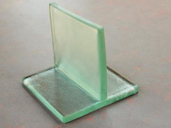
The development of structural glass has been moving towards more transparency (Rammig, 2016). As a result of this preference of clients and architects, glass connections have become more transparent. Currently, fully transparent connections are being developed with silicones and adhesives. However, it can also be achieved by making heat bonds. The aim of this research is to create fully transparent, mono-material connections. (see Fig. 1).
This paper is based on a master thesis at the TU Delft, conducted with ABT ingenieurs BV, a building engineering firm with a specialization is innovative glass structures. The thesis is publicly available on the TU Delft repository, (Eskes, 2018).
Heat bonded glass creates transparent possibilities beyond the flat shape in which glass in generally produced. In regular structural design, the shape of members is altered for structural benefits, like I-beams, trusses and spaceframes. With heat bonds, these become a fully transparent possibility. Plate members can be fused to fins for stiffness. The cross section of glass elements can be increased where-ever necessary, to add material where stress otherwise would peak.
Heat bonding glass where it is needed can reduce material use. Another application, currently researched (Rammig, 2012) (Klein & Oxman, 2015) is the method of 3D printing of glass, which provides the largest freedom of geometry. Glass connection elements can be designed to fit like a puzzle piece, similar to consoles in concrete structures. The freedom of shape will result in new icons in glass engineering. An idea for a near future application in interior design is a shower wall with an all-transparent corner connection.
2. Heat Bonded Glass
In this research, two methods of heat bonding have been considered. The difference among them is the introduction of the heat, which is local, resulting in glass welding; or global, resulting in kiln formed glass fusion, or fusing, as it is shortened further in this paper.
2.1. Weld
The glass weld has been researched for structural applications. In 2008, research is performed into welded borosilicate tubes for an application in façades (Giezen, 2008) (Bos et al. 2007) (Bos et al. 2008). Perpendicularly connected tubes have been produced and tested under different loading conditions. In this research literature, it is stated that the weld is not generally weaker than the parent material.
The welding of borosilicate flat glass is researched to accommodate for 3D printing in glass (Rammig, 2016). Rammig has heated borosilicate flat glass to working temperature and exposed the specimen to a controlled annealing process. She concluded that with a proper annealing process, residual stress can be reduced to a level at which the glass can be considered annealed glass.
In both research series, the used material is borosilicate. This glass type is preferred over the less costly soda lime glass due to its much lower coefficient of thermal expansion (Rammig, 2016). This leads to lower thermal stress and therefore, the risk of thermal shock failure is lower.
In 2006, an exploratory, experimental research has been performed into soda lime glass welding (Belis, Callewaert, & Van Impe, 2006). Several techniques were applied to create welds and the samples were tested mechanically. They concluded that welding soda lime glass is possible. Specimens failed during production due to thermal shock failure. Two methods were proven to prevent thermal shock failure: preheating the glass and heating the glass from both sides with a double torch.
2.2. Fusion
Kiln formed glass fusion is a method usually applied by glass artists. There are documents in the glass art community published to aid in the production of art (Bullseye Glass Co., 2009). In 2015, glass fusion was researched in relation to air entrapment in the glass art (Mitchell J. , 2015). The difference to welding is that with fusing, the whole system is heated to a certain temperature to join the glass. The temperature of the oven influences the product. At relatively high temperature, the fused connection will be stronger, but the edges of the glass will soften. Dams and moulds can be used to limit deformations.
2.3. Method
The knowledge of the production methods displays limits to the product. Both methods are limited to the size of the oven, because the welded system is preferably preheated and annealed and the fused system is produced in an oven. Additionally, the final dimensions of the product should be controlled to create a product fit for the building industry.
This research was aimed to expand this knowledge to a new scale. First of all, the aim was set to connect 10 mm thick float glass, because this thickness is often applied in glass structures. Second, it was decided that the objects were to be made of soda lime glass, because this type of glass is cheaper and is more generally applied in structures.
The 10 mm thick soda lime float glass plates were to be perpendicularly connected in a T-shape. The designed heat bond had a length of 100 mm.
3. Structural Safety
When considering structural applications, an engineer has to consider practical challenges and risks. Professionals designing with glass adopt several approaches to ensure the structural safety (Bos, 2009). The consensus is, that it should always be taken into account that the glass element fails. If this happens, injury should be prevented, the remaining structure has to be able to withstand reasonable loading and the element should be replaced without bankrupting the owner. Heat bonds challenge this failure scenario, for the heat bonded system should be considered as one glass object that collapses at failure. The bond does not stop a crack from propagating.
The measures to ensure structural safety in heat bonded glass can be the same as have been applied in glass engineering so far. Structural glass’ safety can be influenced by three basic strategies: creating secondary load transfer mechanisms, protection and over dimensioning (Bos, 2009). These strategies can be used on the scale of the system and the structure. Future solutions for the heat bonded systems are lamination, reinforcing and tempering. On a structural level, safety can be ensured by a combination of creating a secondary load transfer mechanism and over dimensioning. In some cases, protection alone might be sufficient. It is advised to use a combination of all three in structural glass design with heat bonded systems.
Further research is recommended, for the solutions within the system are currently not available. It should be researched if and how the systems can be laminated, tempered or reinforced. In the near future, it is recommended to apply safety measures within the structure, for these are readily available.
4. Glass Weld
A production method for the glass weld has been developed in collaboration with Frans Folst and Tom Jansen, who ae glass blowing teachers at the Leidsche Instrumentmakers school, the Netherlands. A technical educational facility in Leiden where glass blowing is taught. Folst and Jansen also executed the experiments.
4.1. Welding Method
The production method required a box oven in combination with a line burner. The burner is a bent copper tube in which holes are drilled, connected to a natural gas supply. When ignited, it is a linear torch, able to heat the to be welded areas from both sides over the length of the weld.
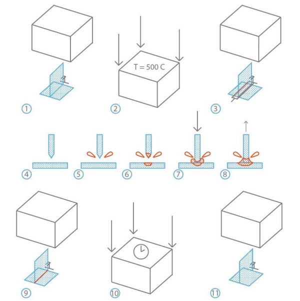
The following steps create the production method (see Fig. 2):
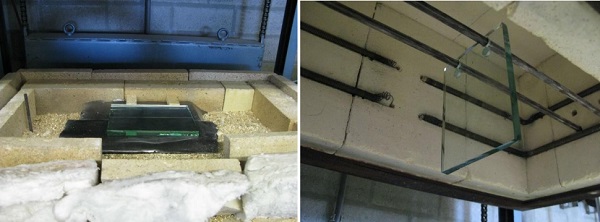
- Step 1: The glass is positioned in the oven in the desired T-shape. The web has to be kept upright by a support.
- Step 2: The oven is closed by lowering the box. The specimen is slowly heated to a temperature of 500°C.
- Step 3: The oven is opened by lifting the box. The line burner is positioned at both sides of the welding zone.
- Step 4: This is the cross section of the welding zone. Note the faceted edge of the web. This is to prevent air inclusions in the joint, as the joint will be made in the center first, pushing the air outward instead of trapping.
- Step 5: The line burner heats the welding zone equally over the length of the weld.
- Step 6: The glass in the welding zone becomes less viscous.
- Step 7: When the viscosity of the glass is low enough, the web is lowered on the flange.
- Step 8: The web is slightly lifted to shape the glass in the welding zone. This will cause the excess glass in the zone to form a smooth fillet weld.
- Step 9: The burner is removed.
- Step 10: The oven is closed. The welded product will reach a homogeneous temperature and be annealed. This process will take several hours.
- Step 11: When the specimen is gradually cooled to room temperature in the oven, the oven can be opened and the welded system can be removed.
4.2. Finite Element Analysis
The glass weld is researched in theory and practice. To reduce the risk of thermal shock failure, finite element analysis is performed. In the model, made with the software Diana FEA, the temperature development over time in the glass is predicted. Based on the material properties of glass, some of them with a relation to temperature, a prediction was made of the stress in the specimen.
The model consists of 3D solid elements. If the glass is liquid, no stress will develop. To simulate this behaviour, some properties of the material have been adapted. A suitable temperature range for the solid, transition and liquid phase of glass have been defined, based on the relaxation of viscoelastic material and the relation between the temperature and the viscosity of glass. The thermal shock failure criterion was set to a principle tensile stress larger than 45 MPa for a significant portion of an element. For an elaboration on the adopted and simulated values and relations, reference is made to the thesis written about this research (Eskes, 2018).
Analyses have been performed to study the sensitivity of the process and to optimize the parameters which can be influenced in execution.
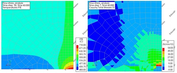
The finite element analysis shows that the bottom surface of the object is most likely to contain significant tensile stress. Preheating the glass showed to be necessary. A higher preheating temperature is advantageous few situations were found where the stress remained below critical level. The first is when the bottom surface of the object near the weld is heated. The second case is when the temperature of the surroundings is maintained at the initial elevated temperature of 500 ˚C. The model showed to be sensitive to alterations of the Young’s modulus and the coefficient of linear thermal expansion.
The recommendations for the production process were to preheat the glass, to heat the bottom of the object and to maintain the surroundings at elevated temperature. Practically, these provisions were complex to create. The limit for the preheating temperature has been set to 500 ˚C to prevent deformation of the glass outside the welding zone.
Heating the bottom surface would most likely require a metal elevated platform supporting the web. The flame would heat the glass through the plate, which would spread the energy over the entire bottom surface. This created the risk of deforming the bottom surface. Also, maintaining the surrounding temperature at 500 ˚C is unpractical, because the glass blower needs to access the glass. It has been tried to keep the temperature around the glass as high as possible.
4.3. Welding Experiments
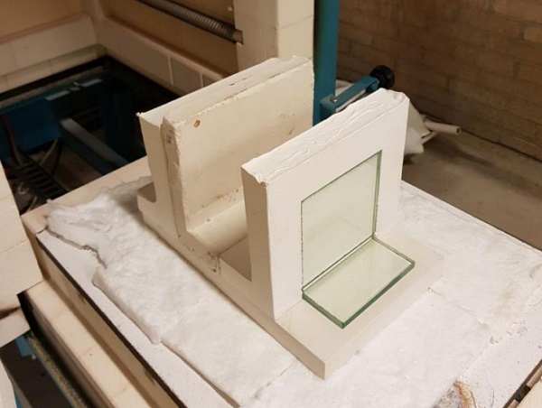
In June of 2018, three glass welding experiments were executed. The glass was prepared and the flange was placed in the box oven. The web was suspended in the oven on metal rods through drilled holes in the glass (see Fig. 4). To allow vertical movement of the box oven when creating the weld, two rows of insulating bricks were put under de rim of the box oven. The top row was to be removed to allow the downward motion of the oven and the glass web to create the weld. The front brick of the bottom row could be removed to insert the burner.
The glass was preheated overnight. The experiment started when the top row of bricks was removed. The front brick was removed and the burner was inserted. The judgement of the experienced glass blower determined when the weld was to be formed. The box oven and the web were lowered to press the web on the flange. After the oven was closed, the object was kept in the 500 ˚C oven for a minimum of four hours, to prevent residual stress. The object was slowly cooled and moved to another oven and slowly annealed and cooled further to room temperature. The annealing was executed by the glass blowers. No data has been gathered considering the annealing temperature schedule.
During the experiments, no thermal shock failure was observed. Additionally, it was observed that it took longer than predicted to heat the glass locally to a sufficient temperature. At the first experiment, there was a slight rush to close the oven as soon as possible. The weld was locally heated when the elements connected and shortly after. At the second experiment, the torch was removed before the web was pressed on the flange, and the oven was closed immediately after. At the third experiment, there was more confidence that thermal shock failure would not occur, and the glass was heated longer before the web was pressed on the flange.
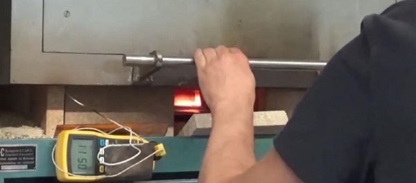
The welding of the second experiment has been caught on camera best (see Fig. 5). On camera, judging from the glow of the material, it can be seen that the web was a few hundred degrees Celsius hotter than the flange. Still, this has not lead to failure.
4.4. Welded Products
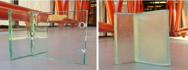
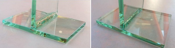
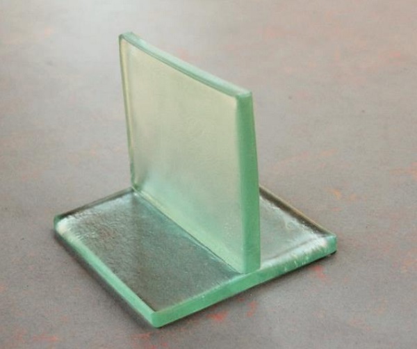
The result of the experiments are three homogeneous T-section in soda lime glass. The objects are transparent. The joints are not perfectly filleted, but improved over the course of the experiments. The aesthetics of the objects are different. The first object showed some sharper corners in the weld, indicating that temperature here has not reached a level to create a filleted joint. The product of the second experiment showed that the web was molten over a less deformed flange (see Fig. 6). The third object had a more filleted joint, though a seam between web and flange was visible.
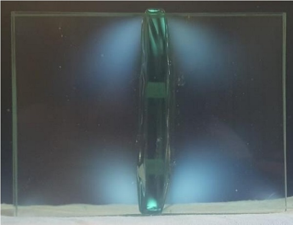
The residual stress in the object was evaluated with images made with polarizing filters. A typical image can be seen in Fig. 7.
4.5. Validation of the Finite Element Analysis
Thermal shock failure did not occur, even though this was predicted to happen if the oven was open and the bottom surface was not heated with the burner. The most probable explanation is an underestimation of the surrounding temperature, resulting in an overestimation of the heat loss to the surroundings. From the photos taken during the experiments, it can be concluded that the surrounding temperature for radiation was most likely the temperature on the inside of the box oven, which was 500 ˚C, though 20 ˚C room temperature was simulated in the analyses.
When the model was simulated with the radiative temperature of 500 ˚C, the results did not predict thermal shock failure. Additionally, the air temperature, which is related to convective heat loss, is shown to be underestimated in the analyses. During experiments two and three, thermocouples measured the air temperature at several positions within the oven. The minimum measured temperature was above 200 ˚C, significantly higher than the modeled convection temperature, which was 20 ˚C.
For further research into finite element analysis of the welding process, it is recommended to obtain more data about the surrounding temperatures during the process and include that in the simulation.
4.6. Conclusions of the Welding Experiments
It is demonstrated that it is possible to weld soda lime float glass with a 10 mm thickness.
Three transparent mono-material joints are proof of the concept. The experiment shows that the process is less sensitive to thermal shock failure than expected based on finite element analysis. It is confirmed that glass welding is possible without thermal shock failure, if the glass is preheated and kept at elevated temperature.
It is important to heat both the flange and the web to get the unified glass joint which was the goal. The experiment in which this did not happen, resulted in a weld where the web was draped over a flange. Heating the joint after the elements are connected could be beneficial.
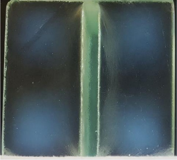
There is residual stress in the welded specimen, but because the polarized light returned only gray-scale images, instead of images with a coloured spectrum, the stress should be considered low (Oikonomopoulou, Bristogianni, Veer, & Nijsse, 2017). The annealing schedule used is clearly adequate.
Over the course of three experiments, the experience and confidence of the team increased. This is a promising prospect for further research.
A few notes are to be made. Due to the small amount of experiments, no strong conclusions can be drawn about the influence of several aspects. Additionally, the difference between the model and the design of the set-up showed to be too large. Overconservative assumptions have in all probability lead to pessimistic modelling.
It is recommended to do the experiment again and with more repetitions, with the aim to find the limits of the process. The influence of preheating temperature, of the duration of the opening of the oven, of the duration of the application of the burner before and after the web is pressed on the flange, are, among others, interesting parameters to research. It could be found when thermal shock failure would occur and what the influence is on the product.
Additionally, it is recommended to research with the aim to expand the possibilities. Is it possible to make multiple welds in one object? Can 4 or 12 mm glass be welded similarly? Expanding the potential of the concept will contribute to its development.
5. Glass Fusion
The research into glass fusion has been mostly practical. Experiments were conducted at faculties of the TU Delft, mainly in the Cast Glass Lab at Civil Engineering and Geosciences. Four experiments have been conducted.
5.1. Fusion Method
The fusion experiments required moulds to control the product’s shape. The mould was made of a gypsum plaster which could be cast in formwork and harden. It has not been achieved to create a one piece mould, because this mould broke during production. It has been decided to use a two or three piece mould. Between experiment one and two, new moulds have been produced, which have been repaired and reused for experiments three and four. Before experiment three, a fillet is created in the inside of the mould.
One mould section was placed in the oven, the glass was inserted and the other mould section was placed against it, enclosing the glass (see Fig. 8). The glass was fused in an oven of which the temperature schedule could be set. In the temperature schedule applied in all four experiments (see Fig. 9), the maximum temperature was 765 °C. The cycle took about 45 hours. Dwells, periods of constant temperature, were included at 630 °C to prevent air inclusions (Mitchell J. , 2015), at the maximum temperature to ensure fusion and at 555 °C and 505 °C to anneal the glass. After the maximum temperature, the glass was quenched to prevent crystallization. This was done by opening the oven door. After quenching, cooling was set to be slowly, to anneal the glass.

Experiment four was conducted in a different oven, where regulations did not allow for quenching by opening the oven door. The glass was cooled at the maximum rate the oven’s insulation allowed, instead of quenched.
5.2. Fusion Products
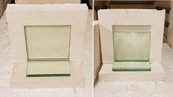
The result of the fusion experiments are translucent, mono-material soda lime T-sections (see Fig. 10).
The first and most important observation was the displacement of the top edge of the web. All specimen had displacements of the same order of magnitude, about 25 mm (see Fig. 11).
The thickness of the flange has increased, with a minimum measured thickness of 11,5 mm and a maximum of 12,5 mm. The thickness of the web has decreased at the top to a minimum of 9,8 mm and increased at the bottom to maximum 12,7 mm.
The objects are translucent. None of them were visibly crystallized. The translucency is due to the texture of the surface. The webs had a finer texture than the flanges and could not be matched with the mould. The top surface of the flange was most transparent. The bottom surface of the flange showed the roughest textures, which matched the surface of the base plate of the mould. All edges were rounded. Most curved in a convex manner, but the top edge of the web was concave. In some objects, deviating shapes were recognized that matched irregularities in the mould. More significant deformations were found with experiment three and again with experiment four.
All objects were joined by fusion. The shape of the joint varied. The first product showed a curve in the web surface over the joint. The other product’s had straighter joints. All joints showed a seam between the web and flange surfaces. The joints of experiments three and four had a larger fillet.
Again, residual stress has been analyzed with images made with polarizing filters (see Fig. 12)
5.3. Conclusions of the Fusion Experiments.
It has been shown to be possible to fuse soda lime glass in translucent T-sections with the described temperature schedule. The glass is joined without visible irregularities in the joint. The joint can be filleted if the mould is adjusted properly. A seam between the elements remains when applying this temperature schedule.
The mould has a significant influence on the product. The deformations, increased thickness and the rounded edges lead to the conclusion that there was space in the mould before fusion. The glass has flown under the influence of gravity. The mould also influences the glass’ surface, especially where gravity affects it, for example at the bottom surface of the flange.
The mould is not the only cause of the translucency. The top edge of the web is translucent as well in all objects, but this edge made no contact with the mould because of gravity.
The new mould of experiment two resulted in a straighter product, but the deformations remained in the same other of magnitude. This leads to the conclusion that the new mould contained additional space before fusion as well, but allowed for more homogeneous deformation. The increase in irregularities on the products of experiments three and four leads to the conclusion that repairing and reusing the moulds has a negative effect on the quality of the products.
The glass was not crystallized during experiment four, even though quenching was omitted. It is concluded that quenching is not necessary for the applied temperature to prevent crystallization.
The residual stress in the object was concluded to be insignificantly low. The used annealing schedule is adequate.
It has not been researched what the influence of the temperature schedule is on the product. All drawn conclusions are therefore only applicable for the applied temperature schedule. It is suggested that increasing the temperature can lead to the elimination of the seam in the joint. However, when the temperature is increased too far, the process will be more similar to casting glass.
It is recommended to research the influence of different temperature schedules. It is also recommended to research measures to control the dimensions of the product. It is recommended to research steel moulds, which can be closed tightly with bolts. Additionally, steel is less vulnerable than plaster and therefore better fit for re-use. It is suggested to study the practice of curving glass, where great dimensional control is executed. Even though this is practiced at lower temperatures (Mitchell G. , n.d.), some techniques might prove to be beneficial. Finally, it is recommended to research the possibilities of post-processing the glass, for example the possibilities of polishing and its influence on the object’s transparency.
6. Structural Test
The products of the weld an fusion experiments have been tested destructively. Additionally, specimen with an adhesive joint between web and flange have been tested. The used adhesive was a thinly layered, stiff and UV-curing adhesive.
The specimen were loaded in shear and bending. A bending and tension set-up have been considered, but it was concluded that a test loaded in bending would put too much emphasis on surface imperfections at the joint and a tension test posed practical challenges which were not preferred.
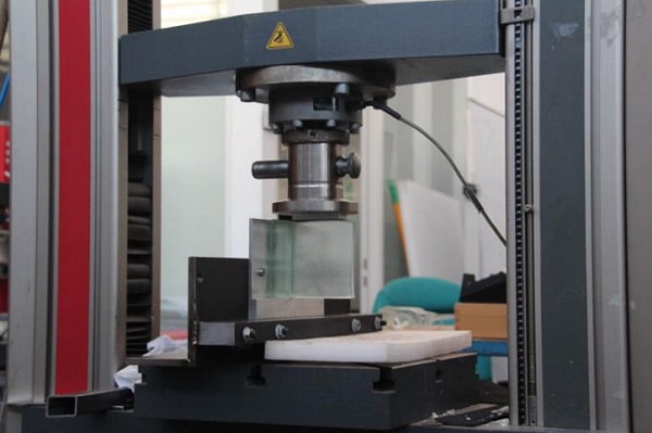
The test set-up is shown in Fig. 13. The flange is adhered to an aluminum plate. The aluminum is bolted to a steel section and connected to the test rig. A displacement controlled compression fixture presses on the web via an aluminum block and rubber strip, distributing the load. The edge of the block an rubber are approximately 5 mm from the joint, to introduce relatively small bending moment in the specimen.
6.1. Results
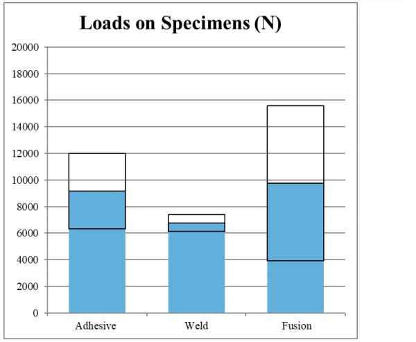
Five adhesive specimen, three welded specimen and four fused specimen have been tested. The averages and standard deviations are displayed in figure Fig. 14. The adhesive specimen failed at the occurrence of the first crack. The welded and fused specimen showed cracks before failure. The force-displacement relation measured by the test rig showed a small reduction in force before increasing further to the maximum load at failure.
The average failure load of the fused specimen was 44% larger than the average failure load of the welded specimen. The standard deviation relative to the mean value was 9% for the welded specimen and 60% for the fused specimen.
6.2. Crack Pattern Analysis
A few crack patterns have been recognized to be recurring in the welded and fused specimen, but not in the adhesive specimen. After elimination of other causes of failure and structural analysis of the test set up using finite element modelling, a combination mechanisms have been determined as most likely cause of cracks. In the finite element results, the areas where cracks have occurred do show elevated stress levels. However, the stress in the glass at the measured failure load is not high enough to be critical.
Therefore, it is concluded most likely that this elevated stress has been combined with a peak stress. This peak stress is most probably caused by invisible imperfections on the surface. It has been determined that the stiffness of the aluminum profile and its connection to the steel has had a large influence on where in the object the stress is elevated. For a more elaborate analysis, reference is made to the thesis written about this research (Eskes, 2018).
It has been investigated what the influence of the joint has been on crack propagation. If the crack propagates along the surface of the joint, it is likely that this joint was weaker than the surrounding material. If the crack propagates between web and flange through the joint without curving, a so-called ‘undisturbed crack’, it is suggested that the joint is like the parent material and therefore homogeneous (see Fig. 15).
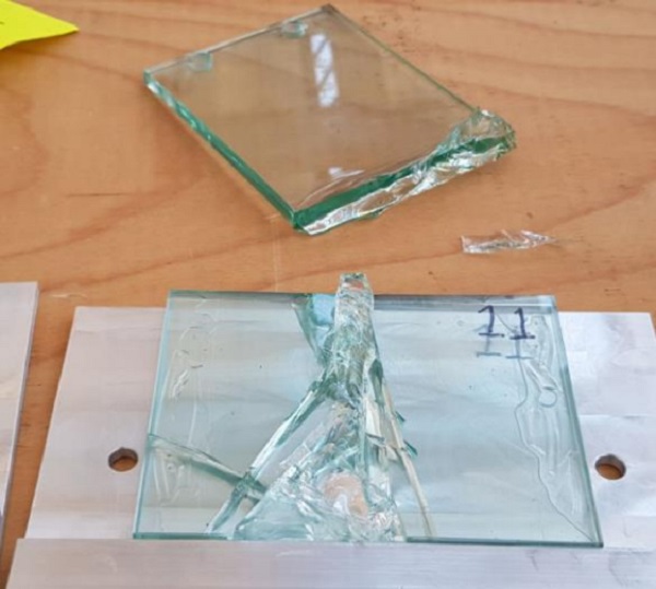
All adhesive specimen show cracks along the surface of the joint, where the adhesive has delaminated. In the welded specimen, one had undisturbed cracks. In the fused specimen, two have cracks along the joint’s plane, and one has undisturbed cracks. The remaining specimen had crack patterns in between; the crack propagating between web and flange bends near the joint, but its surface does not coincide with the joint plane.
6.3. Conclusions of the Structural Test
The failure loads of the welded specimen show the smallest average and the smallest standard deviation. The failure loads of the fused specimen show the largest average and the largest standard deviation. All specimen have failure loads in the same order of magnitude.
The welded and fused specimen showed initial cracks before ultimate failure. The most likely causes observed recurring cracks have been determined to be a result of elevated stress due to the applied load in combination with peak stress due to imperfections or stress concentrations.
In most cases of the welded and fused specimen, the crack surface does not coincide with the joint plane, suggesting that the joint is not significantly weaker than the parent material.
The amount of tests is too low for statistically relevant data. Therefore, the conclusions about capacity based on these tests are limited to the above. Shear stress in the joint is not relevant for these conclusions, because this has most likely not been the cause of failure.
Additionally, it is noted that the test set-up has had a large influence on the failure of the specimen. It has been shown that executing a pure shear test is challenging, as bending moment has been introduced in the specimen.
Furthermore, it should be noted that no definitive conclusion can be drawn about the joint compared to the parent material, as both were loaded differently in the test. If this is to be determined, two plates should be joined to form a larger plate and a four-point bending test should be executed.
It is recommended to reconsider the design of the aluminum-steel test rig and to perform the test a sufficient number of times to create a significant statistical basis. Additionally, it is recommended to test the joint under different loading conditions, for example in tension, to further analyze the structural capacities.
7. Conclusions and Recommendations
The structural safety of the heat bonded system can be provided by tempering, laminating and reinforcing the glass system, though this requires additional research. Outside of the system, safety can be provided by protecting, overdimensioning and creating a secondary load transfer mechanism.
For all specimen, it is concluded that the applied annealing schedule has been appropriate to prevent residual stress sufficiently.
It is possible to weld soda lime float glass of a structurally relevant thickness. The risk of thermal shock failure can be reduced by heating the to be welded areas from all sides or by maintaining the surroundings at elevated temperature. The latter has been applied successfully in the experiments.
It is possible to fuse soda lime float glass of a structurally relevant thickness. The mould has a paramount influence on the quality of the product. It has an influence on the texture of the surface and the aesthetics of the product. It also influences the deformations during production and the dimensions of the product.
The failure loads of the adhesive, welded and fused specimen are of the same order of magnitude. The average is the largest for the fused specimen and the spread is the smallest for the welded specimen.
In the welding and fusion experiments, the aim has been to produce specimens. Preference has been given to creating a product and proving the concept, and the limits of production are therefore unknown. Therefore, it is recommended to research both production methods with the aim to find the limits of the processes. This could create knowledge about the conditions required to prevent thermal shock failure during welding, or the influence of temperature schedules on the fused products.
This research is an exploratory study into heat bonded systems. The surface of the topic has been brushed, to peek into the possibilities and challenges of this concept. All conclusions are based on results of small series: three welding experiments, four fusion experiments and a structural test with series of five, three and four specimens per type. With more repetitions, more knowledge is gathered on the production methods and the possibilities and limits in application. It is therefore highly recommended for future research to improve the experiments and execute them with a statistically relevant amount of repetitions.
8. References
Belis, J., Callewaert, D., Van Impe, R., De Beule, M.: Seamless connection of soda-lime float glass by welding: preliminary test results. In International Symposium on the Application of Architectural Glass (ISAAG 2006) 235-241 (2006)
Bos, F. P., Veer, F. A.: Bending and buckling strength of butt-welded borosilicate glass tubes. In 3rd International Conference on Structural Engineering, Mechanics and Computation, Cape Town, South Africa (2007)
Bos, F., Giezen, C., Veer, F., Louter, C.: Cable-stayed façade structure with welded borosilicate glass tubes. In Structures Congress 2008: Crossing Borders 1-10 (2008)
Bos, F. P.: Safety Concepts in Structural Glass Engineering. Doctoral thesis, TU Delft, Delft (2009)
Bullseye Glass Co. Technotes 1 to 7. A Technical Supplement from Bullseye Glass Co. (2009)
Eskes, A.M:. Connecting Glass to Glass with Glass. Master thesis, TU Delft, Delft (2018)
Giezen, C.: Development of a Structural Element of Glass with Glass Welding Processes. Master thesis, TU Delft, Delft (2008)
Klein, J., & Oxman, N.: Additive Manufacuring of Optically Transparent Glass. Master thesis, Massachusetts Institute of Technology, Cambridge, U.S.A (2015)
Mitchell, G. (n.d.). How is curved glass made? Retrieved from Science Focus: www.sciencefocus.com/science/how-is-ccurved-glass-made
Mitchell, J.: Precision Air Entrapment through Applied Digital ans Kiln Technologies: A New Technique in Glass Art. Doctoral Thesis, Univresity of Sunderland, Sunderland, UK (2015)
Oikonomopoulou, F., Bristogianni, T., Veer, F. A., Nijsse, R.: The construction of the Crystal Houses façade: challenges and innovations. Glass Struct. Eng. 3(1), 87-108 (2018)
Rammig, L.: Direct Glass Fabrication–New applications of glass with additive processes. Challenging Glass, 3, 315-321 (2012)
Rammig, L.: Residual Stress in Glass Components. In Challenging Glass Conference Proceedings, Vol. 5, 305-214 (2016)