Article Information
- Digital Object Identifier (DOI): 10.47982/cgc.10.700
- Published by Challenging Glass, on behalf of the author(s), at Stichting OpenAccess.
- Published as part of the peer-reviewed Challenging Glass Conference Proceedings, Volume 10, June 2026, 10.47982/cgc.10
- Editors: Christian Louter, Freek Bos & Jan Belis
- This work is licensed under a Creative Commons Attribution 4.0 International (CC BY 4.0) license.
- Copyright © 2026 with the author(s)
Authors: Bert Van Lancker a,b , Cas Maertens a , Jérôme Van Alboom a , Roman Wan-Wendner a , Jan Belis a
a Ghent University, Belgium
b vitroplena, Belgium

Abstract
The use of adhesives in architectural glass applications is steadily increasing. To date, these applications have primarily focused on structural glass-to-metal or glass-to-glass connections in façades, typically employing flexible adhesives such as silicones and polyurethanes. Recently, however, there has been a growing interest in stronger adhesives, such as acrylates and epoxies, for all-glass assemblies and for hybrid structures combining glass with materials including timber, plastics, and concrete. This emerging trend forms the basis of the present research in which glass is combined with concrete. To develop and optimise such hybrid components, finite element simulations can be employed, provided that the adhesive behaviour is accurately represented. For this purpose, experimental testing of both bulk adhesive material and bonded glass–concrete interfaces is required to establish the relevant stress–strain relationships. In this study, the mechanical properties of an epoxy adhesive selected for glass–concrete bonding are characterised through tensile and shear testing. Tensile tests are performed on dumbbell specimens, while compressive double-lap shear tests are carried out on bonded glass–concrete specimens. This paper presents the adopted test procedures based on relevant standards, the fabrication of the specimens, the resulting experimental data, a simplified material model, and the implementation in finite element software for comparison purposes.
1. Introduction
The use of structural glass as load-bearing material is accelerated by the increasing ambition of contemporary architecture to maximise transparency. Glass offers exceptional compressive strength and transparency, though its brittle nature and sensitivity to surface flaws necessitates the hybridisation with other materials to overcome undesired failure behaviour, to introduce ductility and to achieve safe and reliable structural performance (Martens et al. 2015). Adhesive bonding has emerged as an important technology in this context, allowing forces to be transferred efficiently between different materials without the need for mechanical fixings or treatments such as drilling or pre-stressing (Van Lancker et al.,2016). As a result, adhesively bonded glass-glass, glass–metal, and glass–timber assemblies are used in for instance façade engineering and interior applications.
Despite this progress, the use of adhesives in glass–concrete hybrid structures remains limited. Conventional concrete exhibits brittle behaviour similar to glass, and early research has shown that glass–concrete bonds often fail through sudden delamination or substrate fracture, even when high-performance adhesives are used (Maertens et al. 2024). Therefore, fibre-reinforced concrete (FRC) and fibre-reinforced ultra-high-performance concrete (FR UHPC) demonstrate enhanced tensile capacity, ductility, and fracture toughness, reducing the brittleness mismatch between glass and concrete (Shemirani 2022). Freytag (2004), for instance, developed an I-shaped beam with a laminated glass web and UHPC flanges. More recently, Maertens et al. (2025) and Van Lancker et al. (2025) developed a large-scale demonstrator (G2C or Glass-to-Concrete) incorporating several bonded glass-to-concrete applications. A bonded glass-concrete staircase using steel-fibre-reinforced UHPC (SFR UHPC), glass balustrades adhesively connected to an FRC slab, a sandwich panel with glass faces bonded to a concrete core, and T-beams comprising a glass web and a fibre-reinforced concrete flange collectively demonstrated the transformative potential of the structurally bonded glass-to-concrete systems during Glass Technology Live at Glasstec 2024.
The challenge when designing hybrid glass-concrete systems lies in the representation of the mechanical behaviour of the adhesive layer which is determined by the geometry, the stiffness and the load-carrying capacity of the adhesive joint (Van Lancker 2020). To enable reliable design and numerical simulation of bonded glass–concrete structures, robust experimental data on adhesive behaviour – both in bulk and at the interface – are essential. Stress–strain curves, failure envelopes, and interface strengths must be established to support finite element modelling and to define appropriate failure criteria. Previous studies mainly explored adhesive performance in glass–metal joints (Belis et al. 2011; Silvestru 2018; Van Lancker 2020), glass-timber joints (Nicklisch 2016, Engelen 2025) or glass-glass joints (Martens 2018). Systematic research of glass–concrete bonds is still limited.
This paper addresses this gap by experimentally characterising the mechanical behaviour of a selected epoxy adhesive intended for structural glass–concrete applications. Tensile tests on bulk adhesive specimens and compressive double-lap shear tests on bonded glass–concrete samples are performed to derive material parameters suitable for numerical modelling. Based on the experimental findings, a simplified material model is proposed and implemented in finite element simulations of both types of tests. The development and optimisation of hybrid glass–concrete components is supported as such.
2. Experimental programme
In cooperation with fischerwerke GmbH & Co. KG (Germany), a two-component injectable epoxy adhesive — classified as a Class A resin according to GB 50550-2010 (2010) and GB 50728-2011 (2011) — was selected as a potential candidate for structural applications in hybrid glass–concrete systems. This selection was based on the inherent properties of the adhesive on the one hand, and the practical experience of the industrial partner with this adhesive in timber-concrete composite panels on the other hand.
The adhesive consists of a low-viscosity, epoxy-based reactive resin. Components A (mortar) and B (hardener) must be mixed in a 3:1 weight ratio. After 8 hours of curing, specimens can be handled, and full curing is achieved after 24 hours. The recommended application temperature ranges from 10 °C to 40 °C. The density of the cured system is 1150 kg/m³, and the open time at 20°C is approximately 80 minutes. Appropriate surface pretreatment is required, and all processing instructions provided by the manufacturer must be followed when using this adhesive system.
2.1. Uniaxial tensile tests
The tensile properties of the epoxy adhesive were determined through uniaxial tensile tests on bulk material in accordance with ISO 37 (ISO 2024) and ISO 527-2 (ISO 2025). These standards enables the determination of tensile stress–strain behaviour of adhesives using dumbbell (dog-bone) specimens, which are loaded along their longitudinal axis at a constant deformation rate until failure occurs. The specimens were fabricated using a PTFE mould, a non-stick material ideal for easy demoulding. The geometry of the Type 2 specimens specified in ISO 37 (ISO 2024) is depicted in Fig. 1, and the corresponding dimensions are summarised in Table 1. The test length for Type 2 specimens equals 20±0.5 mm, which shall not exceed the length of the narrow portion of the test piece, i.e. C in Fig. 1.
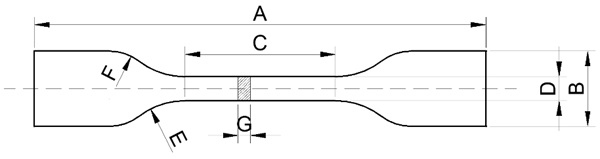
Table 1: Dimensions of a dumbbell specimen (Type 2) according to ISO 37 (ISO 2024).
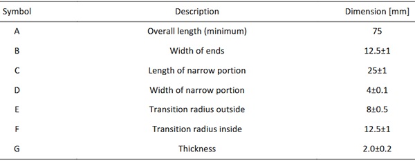
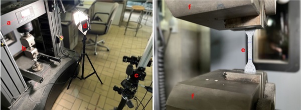
Component A and B of the epoxy adhesive system were mixed in the prescribed 3:1 weight ratio. Using a glass vacuum-degassing chamber, air inclusions in the mixture were removed before applying the adhesive. The low-viscosity mixture was deposited into the PTFE moulds using a syringe to control the specimen volume, after which any excess adhesive was removed with a scraper. Following 24 hours of curing in a climatic chamber at 20 ± 1 °C and 60 ± 3% relative humidity, the specimens were carefully demoulded, taking special care to avoid any damage prior to testing. The specimens were then stored for an additional six days in the same climatic conditions. After this conditioning period, the cross-sectional area A0 of each specimen was measured to enable the calculation of the engineering stress in the specimens. Uniaxial tensile tests were then performed using an Instron 5982 dual-column universal testing machine (UTM) equipped with a 100 kN load cell (accuracy class 0.2%). A deformation rate of 1 mm/min, in accordance with ISO 527-2 (ISO, 2025), was considered to represent quasi-static loading. A digital image correlation (DIC) system was used to measure the strain field in the specimens. Two Prosilica GT19100 cameras with a resolution of 1920 × 1080 pixels (2.1 MP), combined with Rodagon smart-focus lenses with a focal length of 80 mm, were installed to form a stereo-vision measurement setup. A connection between the DIC system and the Instron machine enabled synchronised acquisition of force data and strain fields on a central computer. A total of five specimens were tested. Fig. 2 depicts the entire setup and a dumbbell specimen being tested.
2.2. Compressive double-lap shear tests
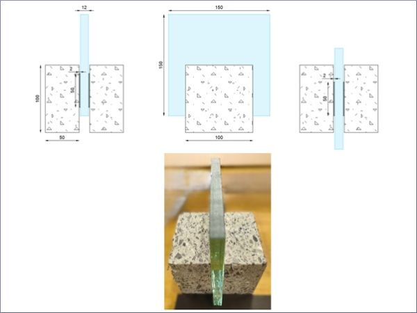
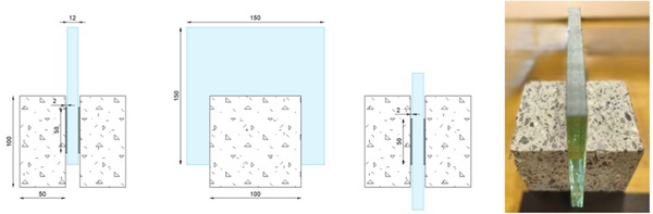
In Wium et al. (2024; 2025), a compressive double-lap shear test was used to determine the shear properties of thick epoxy glass–steel bonds. In this research, similar specimens—substituting concrete for steel—and a comparable test setup were adopted. The double-lap shear specimens consisted of two fibre-reinforced concrete (FRC) blocks measuring 100 mm by 100 mm by 50 mm. The concrete blocks were cast using C40/50 self-compacting concrete with CEM II/A 52.5 N cement and aggregates with a maximum diameter of 14 mm. Dramix 3D 65/60 steel fibres were added at a dosage of 35 kg/m³. Compressive tests on standardised cylinders were performed to characterise the mechanical properties of the concrete as a reference. A single monolithic 12 mm thick annealed glass plate measuring 150 mm by 150 mm was bonded between the concrete blocks using the epoxy-based adhesive system, creating two bond areas of 50 mm by 50 mm each with an adhesive layer thickness of 2 mm. The adhesive joints were positioned 12.5 mm from the substrate edges to minimise edge effects. Fig. 3 depicts a schematic figure and a photo of the double-lap shear test specimens.
Specimen preparation began with thorough cleaning and degreasing of the glass substrates using isopropyl alcohol. The concrete substrates were cleaned using first a brush and then a damped lint-free cloth. Double-sided VHB tape with a thickness of 2 mm was used to create moulds for producing the 50 mm by 50 mm by 2 mm adhesive bonds between the glass substrate and the concrete blocks. Several auxiliary tools ensured proper alignment of all components. The top surface of the glass plate - where the compressive load would be introduced - was ground to minimise local defects.
After preparing the epoxy-based adhesive system in accordance with the manufacturer’s processing instructions, a syringe fitted with a heat-shrink tube was filled with the required volume. This setup enabled bottom-up injection of the adhesive into the moulds, reducing the risk of air entrapment within the adhesive layer. Following production, the specimens were stored at 20 ± 1 °C and 60 ± 3% relative humidity for seven days prior to testing. A total of three specimens was produced.
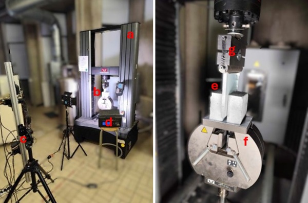
Compressive double-lap shear tests were performed using the aforementioned UTM and load cell. The specimens were positioned on a solid, flat base, and no lateral restraints were applied, allowing the concrete blocks to move horizontally during loading to ensure simple shear in the adhesive layers. The compressive load was introduced through a self-levelling steel cylinder. To avoid direct hard contact between steel and glass, an aluminium plate was placed between the cylinder and the glass edge. Test were conducted in a displacement-controlled manner at a speed of 0.2 mm/min.
A DIC system, as previously described, was used to measure the strain fields in both the concrete blocks and the glass plate. This approach enabled the determination of relative displacements between the glass and concrete, from which shear stress–shear strain curves were derived. Direct measurement of strain within the adhesive layer itself was not feasible due to the limited thickness of the adhesive layers and the recessed adhesive surface in relation to glass and concrete. Fig. 4 depicts the test setup.
3. Finite element modelling
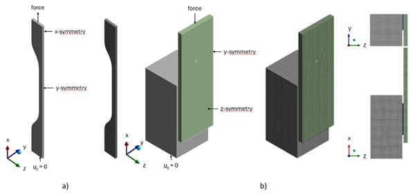
Three-dimensional finite element models of a nominal dumbbell specimen and a nominal compressive double-lap shear specimen, both incorporating double-symmetry boundary conditions, were developed in Ansys®. These simulations enable the investigation of the material properties derived from the uniaxial tensile tests and the compressive double-lap shear tests described in Section 2.
The epoxy-based adhesive was modelled as a linear elastic material, with its Young’s modulus and Poisson’s ratio obtained from the experimental tensile tests (cfr. infra). A hex-dominated quadratic brick mesh was used for the adhesive layer. For the glass components, linear elastic behaviour was assumed, with an elastic modulus of 70 GPa and a Poisson’s ratio of 0.23 (EN 16612, 2019). The steel-fibre-reinforced concrete C40/50 was also modelled as linear elastic, using a Young’s modulus of 35 220 MPa and a Poisson’s ratio of 0.2 (EN 1992, 2023). Both the glass and concrete components were meshed using quadratic brick elements in a hex-dominated configuration. A tie constraint was applied between the glass and adhesive, and between the concrete and adhesive, assuming a perfect bond. The adhesive layer was defined as the slave within the master–slave formulation of the constraint.
A mesh-convergence study was performed to determine the optimal mesh density and the appropriate element-size ratio between the glass/concrete and adhesive regions. The adhesive layer was discretised using four elements through its thickness, and an element-size ratio of 4:1 was adopted between the adhesive and the adjacent glass and concrete regions. Boundary and loading conditions were applied to replicate the actual experimental setups. Fig. 5 illustrates the numerical models for both test specimens.
4. Results and discussion
4.1. Uniaxial tensile tests
The relationship between the tensile stress 𝜎, defined as the ratio of the applied force 𝐹 to the initial cross-sectional area 𝐴₀ of the narrow portion of the dumbbell specimen, and the tensile strain 𝜀𝑥, obtained from the digital image correlation analyses, can be established for each specimen. From the individual tensile stress-strain curves, an average curve up to failure of the first specimen can be derived. Remark that, in accordance with the relevant standards, only specimens that fail within the narrow portion of the dumbbell specimen are retained. Fig. 6 depicts the individual curves and average curve for the investigated epoxy-based adhesive system tested at a displacement rate of 1 mm/min.
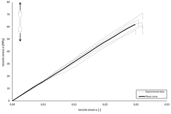
The tensile stress–strain curves of the epoxy-based adhesive exhibit linear elastic behaviour up to the point of brittle failure, characterised by the failure stress 𝜎𝑢lt and the failure strain 𝜀𝑢lt. From these curves, the Young’s modulus 𝐸 can be determined in accordance with the calculation procedure specified in ISO 527-1 (ISO, 2019) and presented by Eq. (1).

where 𝐸 = Young’s modulus
𝜎₁= the stress in MPa as measured on the deformation value of 𝜀₁ = 0.0005
𝜎₂= the stress in MPa as measured on the deformation value of 𝜀₂ = 0.0025
From the DIC measurements, not only the longitudinal strains 𝜀𝑥 (parallel to the loading direction) of the dumbbell specimen can be obtained, but also the transverse strains 𝜀𝑦 (perpendicular to the loading direction). Knowledge of both strain components enables the determination of the Poisson’s ratio 𝜈 using Eq. (2):

For an isotropic material, the shear modulus 𝐺 can be derived from the Young’s modulus 𝐸 and the Poisson coefficient 𝜈 based on continuum mechanics theory using Eq. (3).

The mean values and standard deviations of the parameters derived from the tensile stress–strain relationships obtained from the five experimental tensile tests are presented in Table 2.
Table 2: material properties of the epoxy-based adhesive obtained from uniaxial tensile tests.
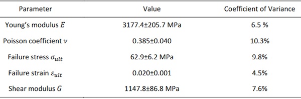
The experimentally obtained material parameters are consistent with values reported in literature for similar epoxy-based adhesive systems, which typically demonstrate Young’s modulus values ranging from 2500 MPa to 4000 MPa and Poisson’s ratios between 0.35 and 0.42 (Wium et al. 2024; 2025).
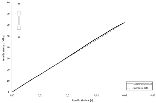
Implementing linear elastic isotropic material behaviour with a Young’s modulus 𝐸 equal to 3177.4 MPa and a Poisson’s ratio 𝜈 of 0.385 in the finite element model of the dumbbell specimen results in a tensile stress–strain response that compares well with the experimental data, as shown in Fig. 7.
4.2. Compressive double-lap shear tests
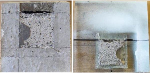
All specimens failed in a brittle manner through cohesive substrate failure in one or both concrete blocks, as illustrated in Fig. 8. Consequently, the inherent shear strength of the epoxy-based adhesive was not fully mobilised, as the failure strength was governed by the properties of the concrete.
From the load cell data and digital image correlation measurements obtained during the compressive double-lap shear tests, shear stress–strain curves were derived. The shear stress 𝜏 was calculated as the ratio of the applied force 𝐹 to the total bonded surface area 𝐴. The shear strain 𝛾 was determined from the relative vertical displacements between the glass and concrete blocks, measured at points P₀, P₁, and P₂ as indicated in Fig. 9. The measurement data were corrected for rigid-body motion using the Removing Rigid Motion post-processing tool in the DIC software. To assess the influence of the VHB tape, an additional compressive double-lap shear test was performed on a specimen without adhesive bonds, confirming that its effect was negligible. From the individual shear stress-strain curves, an average curve up to failure of the first specimen was derived. Fig. 9 depicts the individual curves and average curve for the investigated epoxy-based adhesive system tested at a displacement rate of 0.2 mm/min, and the locations of the DIC measurement points on the specimens.
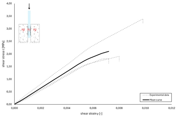
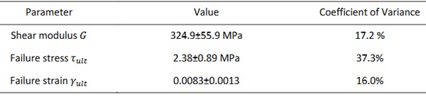
The shear stress–strain curves of the epoxy-based adhesive exhibit linear elastic behaviour up to the point of brittle failure, characterised by the failure stress 𝜏𝑢lt and the failure strain 𝛾𝑢lt. From these curves, the shear modulus 𝐺 is determined as the slope of the linear portion of the stress–strain response. Table 3 summarises the mean values and standard deviations of the parameters derived from the shear stress-strain relationships obtained from the three experimental shear tests.
Table 3: material properties of the epoxy-based adhesive obtained from compressive double-lap shear tests
A comparison between the shear moduli obtained from the uniaxial tensile tests and the compressive double-lap shear tests reveals a significant difference between the resulting values. This discrepancy is expected to stem from the differences in specimen geometry and loading configuration, as well as from the DIC-based strain measurements. To gain further insight, a numerical investigation of the compressive double-lap shear test was performed. In this analysis, the finite element model of the specimen was assigned linear elastic material behaviour for the epoxy-based adhesive layer, using the material properties obtained from the uniaxial tensile tests, i.e. 𝐸 = 3177.4 MPa and 𝜈 = 0.385. Fig. 10 depicts the vertical displacement of the concrete block, the adhesive layer, and the glass plate, together with the shear stress distribution in the adhesive layer at a load of 12 kN (corresponding to a nominal shear stress of 2.4 MPa). The results clearly demonstrate that neither the shear stress nor the shear strain is uniform across the bonded area. As such, the relative displacements between the glass and concrete vary significantly over the interface.
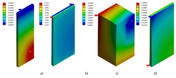
Fig. 11 depicts the relationship between the nominal shear stress 𝜏 - defined as the applied total force divided by the total bonded area - and the local shear strain 𝛾 derived from the relative displacement between the glass and concrete at different locations as indicated in the figure. P₀, P₁, and P₂ correspond to the experimental measurement locations. P₄ and P₅ are located near the adhesive interface with the concrete and glass, respectively. The displacements at P₄ and P₅ are extracted both at the front edge of the adhesive layer and at the centre line of the layer. These graphs demonstrate that, at the centre of the bonded area, the shear modulus obtained is comparable to the value expected based on the uniaxial tensile tests (1147.8 MPa vs. 1222.9 MPa (Δ = 6.1%)). The shear response captured by the digital image correlation setup during the compressive double-lap shear tests aligns well with the numerical predictions at the same locations (324.9 MPa vs. 337.7 MPa (Δ = 3.8%)). However, these local measurements are not representative of the overall shear modulus of the epoxy-based adhesive system. The variability in the calculated shear modulus is further illustrated by the value obtained from the relative displacements at the front edge of the adhesive layer, i.e. P₄–P₅ (front), which lies between the extreme values derived from P₄–P₅ (centre) and P₀–P₁–P₂. These observations of asymmetric shear stress distributions in the adhesive layers are consistent with the conclusions reported by Hart-Smith (2002).
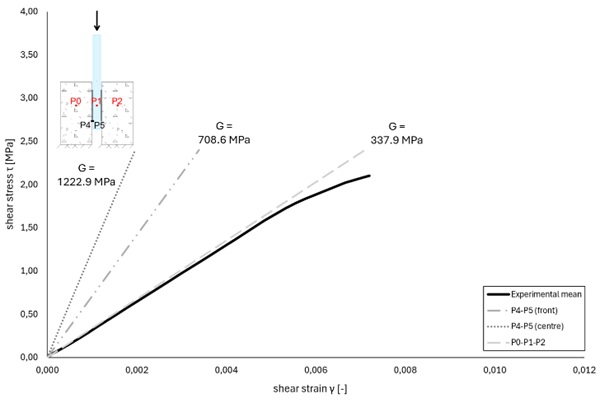
The comparison between the experimental and numerical results shows that compressive double-lap shear tests provide valuable insight into the shear response of the bonded glass–concrete system, particularly regarding the failure mode and overall shear strength. However, the intrinsic shear properties of the epoxy-based adhesive cannot be determined from these experiments alone. Only through the numerical model, implemented with the material properties obtained from the uniaxial tensile tests, can the complete shear stress distribution within the bonded system be examined. A combination of both test types is therefore essential: the uniaxial tensile tests capture the intrinsic material behaviour of the adhesive, while the compressive double-lap shear tests reveal the structural response of the bonded glass–concrete assembly.
There is a considerable dispersion in the results obtained from the uniaxial tensile tests, which can be attributed to the intrinsic sensitivity of the adhesive to several parameters, including mixing ratio, relative humidity and temperature during production, storage and testing, etc. Further optimisation of the compressive double-lap shear test specimens and setup is also recommended to minimise dispersion of the results. It should additionally be noted that the present study considers only isotropic linear elastic material behaviour. A failure criterion for the adhesive itself, as well as for the bonded glass–concrete system incorporating this adhesive, has not yet been defined.
5. Conclusions
In this research, a two-component epoxy-based adhesive for structural glass–concrete applications was characterised through complementary bulk tensile tests, compressive double-lap shear tests, and finite-element simulations.
Uniaxial tensile tests on five dumbbell specimens showed a linear elastic response up to brittle failure (𝜎𝑢lt = 62.9±6.2 MPa, 𝜀𝑢lt = 0.020±0.001), characterised by a Young’s modulus 𝐸 equal to 3177.4 ± 205.7 MPa and a Poisson’s ratio 𝜈 equal to 0.385 ± 0.040. This results in a calculated shear modulus 𝐺 of 1147.8 ± 86.8 MPa. These experimentally obtained values lie within the expected range for comparable epoxy-based adhesive systems.
Implemented in an finite element model of the dumbbell specimen as an isotropic linear elastic material (𝐸 = 3177.4 MPa, 𝜈 = 0.385), the simulations reproduced the measured tensile stress–strain response with close agreement, confirming that the identified parameters are suitable for numerical prediction of the intrinsic adhesive behaviour.
Compressive double-lap shear tests on three glass–concrete specimens failed by cohesive fracture of the concrete substrate, indicating that the adhesive’s intrinsic shear capacity was not fully mobilised in this configuration. Interface-level measurements nevertheless provided a shear modulus 𝐺 equal to 324.9 ± 55.9 MPa in combination with 𝜏𝑢lt = 2.38 ± 0.89 MPa and 𝛾𝑢lt = 0.0083 ± 0.0013.
Finite element analyses of the double-lap configuration clarified the pronounced stress/strain non-uniformity across the bonded area. The model demonstrated strong gradients in shear stress and relative displacement over the bond. Locally, the centre-region shear modulus was 1222.9 MPa, closely matching the bulk-derived value of 1147.8 MPa (Δ = 6.1%). The DIC-based measurement of 324.9 MPa aligned with the lower apparent modulus of 337.7 MPa (Δ = 3.8%), demonstrating that DIC readings at accessible surfaces do not capture intrinsic material behaviour.
Overall, the study shows that bulk tensile tests are essential to identify intrinsic adhesive properties for modelling, while double-lap shear tests reveal system-level responses and failure modes of glass–concrete assemblies. The dispersion observed in both test series underscores sensitivity to production and environmental parameters and motivates further refinement of specimen preparation and setup to reduce variability. Future work will expand the experimental matrix to further investigate the effects of temperature, artificial ageing, cyclic loading, etc. on the material properties of the adhesive, as well as the derivation of an appropriate failure criterion for bonded glass-concrete components using this epoxy-based adhesive system.
References
Belis, J., Callewaert, D., Van Hulle, A.: Bouwen met glas en adhesieven – praktische gids voor ontwerper en uitvoerder (in Dutch). Ghent University (2011).
CEN/TS 19100:2021: Design of Glass Structures, European Committee for Standardisation, CEN (2021).
EN 1992:2023 Eurocode 2 – Design of concrete structures. European Committee for Standardisation, CEN (2023).
EN 16612:2019: Glass in building – Determination of the lateral load resistance of glass panes by calculation, CEN (2019).
Engelen, T.: Mechanical characterisation and structural design of hybrid timber- glass diaphragms with integrated photovoltaics. UHasselt, Belgium: Doctoral dissertation (2025).
Freytag, B.: Glass-concrete composite technology. Structural Engineering International, 14(2), 111-117 (2004).
GB 50550-2010: Code for acceptance of construction quality of strengthening building structures. Ministry of Housing and Urban-Rural Development. General Administration of Quality Supervision, Inspection and Quarantine. People’s Republic
of China (2010).
GB 50728-2011: Technical code for safety appraisal of engineering structural strengthening materials. Ministry of Housing and Urban-Rural Development. General Administration of Quality Supervision, Inspection and Quarantine. People’s
Republic of China (2011).
Hart-Smith, L. J.: The design of adhesively bonded joints. In Dillard, D.A., Pocius, A. V., Chadhury, M. (Eds.), Adhesion Science and Engineering, Chapter 19 (2002).
ISO 37:2024: Rubber, vulcanized or thermoplastic – Determination of tensile stress-strain properties. International Standard Organization, ISO (2024).
ISO 527-1:2019: Plastics – Determination of tensile properties – Part 1: General principles. International Standard Organization, ISO (2019)
ISO 527-2:2025: Plastics – Determination of tensile properties – Part 2: Test conditions for moulding and extrusion plastics. International Standard Organization, ISO (2025)
Maertens, C., Van Lancker, B., Proia, A., Wan-Wendner, R., Belis, J.: Investigation of glass-to-concrete adhesive joints through three-point bending tests. Challenging Glass Conference Proceedings, Vol. 9 (2024).
Maertens, C., Van Lancker, B., Callewaert, D., Wan-Wendner, R., Belis, J.: Hybrid Glass-to-Concrete pedestrian bridge: a case study. Proceedings of the Glass Performance Days 2025, 11-12 June, Tampere, Finland (2025).
Martens, K., Caspeele, R., Belis, J.: Development of composite glass beams – A review. Engineering Structures, 101, 1-15 (2015).
Martens, K.: Statically indeterminate reinforced glass beams. Doctoral dissertation, Ghent University, Belgium, ISBN 9789463551328 (2018).
Nicklisch, F.: Ein Beitrag zum Einsatz von höherfesten Klebstoffen bei Holz-Glas- Verbundelementen (in German). Doctoral dissertation. Germany: Dresden University of Technology (2016).
Shemirani, A.B.: Effects of Fiber Combination on the Fracture Resistance of Hybrid Reinforced Concrete. Iranian Journal of Science and Technology, Transaction of Civil Engineering, 46, 2161-2172 (2021).
Silvestru, V. A.: Composite structural glazing systems – Towards transparent building envelopes with composite structural behaviour between glass panes and metal framing by adhesive bonding. Austria: Doctoral dissertation. Graz University of Technology (2018).
Van Lancker, B.: Experimental and numerical investigation of two-sided bonded glass-steel façade units. Doctoral dissertation, Ghent University, Belgium, ISBN 9789463554282 (2020).
Van Lancker, B., Dispersyn, J., De Corte, W., Belis, J.: Durability of adhesive glass-metal connections for structural applications. Engineering Structures, 126, 237-251 (2016).
Van Lancker, B., Maertens, C., Wan-Wendner, R., Belis, J.:. Numerical investigation of bonded glass-to-world concrete applications subjected to real-world design situations. Proceedings of the Glass Performance Days 2025, 11-12 June, Tampere, Finland (2025).
Wium, D., Van Lancker, B., Lataire, E., Belis, J.: Experimental work on thick epoxy adhesive bonds for glass-steel joints in aship. Challenging Glass Conference Proceedings, Vol. 9 (2024).
Wium, D., Van Lancker, B., Belis, J., Lataire, E.: Mechanical behaviour and durability of an epoxy adhesive for structural glass-to-steel connections in a ship. International Journal of Adhesion and Adhesives, 141, 104050 (2025).