
Authors:
Francesca Lugaresi, Bartłomiej Sędłak, Panagiotis Kotsovinos, Guillermo Rein
Published by Elsevier Ltd. - Fire Safety Journal, Volume 140 (2023) 103850
DOI: https://doi.org/10.1016/j.firesaf.2023.103850
Abstract
Curtain walls are the most common façade system for modern office buildings. These facade systems play an important role in containing the fire to the floor of origin, and in the case of failure, the consequences can be severe. The heat from a fire could cause key elements to fail and sections of the facade to detach and fall from the building, facilitating flame spread to upper floors. However, no tools currently exist that can reliably predict the failure of such systems. This study computationally investigates the thermal response of two curtain wall framing systems to fire exposure – the stick system and the unitized system. The model predictions were validated against experimental data and the role of the screw connector is explored.
A typical curtain wall aluminium frame system is modelled. The simulation results indicate that when heated from a compartment fire, thermal degradation of the aluminium frame is very rapid, occurring within the first 15 min of fire exposure for ISO-834 standard fire. When heated from the outside, considering the Eurocode external fire, thermal degradation of the pressure plate occurred within 10 min. With the addition of thermal protection or when using steel instead of aluminium profiles, thermal degradation was not predicted within the first 40 min of heating. The findings advance our understanding of curtain wall frame fire behaviour and can help develop more effective fire strategies and more resilient systems.
1. Introduction
When a fire breaks out in a building, the fire safety strategy in place should guarantee the safe evacuation of everyone in and around the building whilst giving safe access for firefighters to tackle the fire. This not only means preventing the fire and smoke from spreading within the building but also limiting the fire spreading externally between floors and preventing parts of the facade from detaching from the building due to stress and degradation caused by the fire. If a section of the facade was to detach and fall from the building, this would pose a life threat and could obstruct the passage of people and equipment at ground level. In addition, the failure of a large section of the facade can facilitate fire spread and can lead to huge economic losses to the building owners due to time and cost of repair.
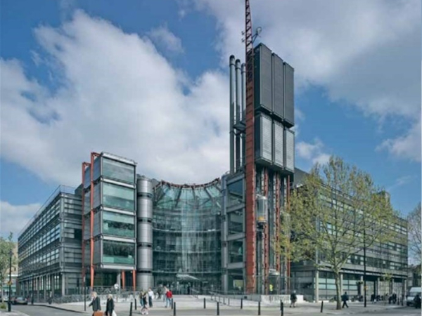
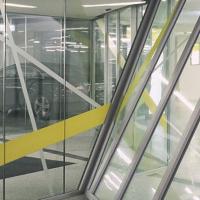
Glazed curtain wall facades are particularly at risk of large parts of the facade detaching due to the poor fire performance of the glass panels and the aluminium frame which are the main components of the system. Aluminium expands and softens rapidly when heated, while glass is likely to crack due to thermal gradients or thermal shock [1]. An example of this was recently seen during a fire at the Relay Building in central London (Fig. 1). The curtain wall facade of the 23-storey building was severely damaged in a fire that spread vertically up three floors and destroyed two apartments. During the fire, large objects were observed detaching and falling from the building, approximately 60 m above street level. Glass panels were seen falling as one large piece (Fig. 1) and shattered at impact with the ground, sending fragments across the street. Metal elements, most likely components of the facade framing system, have also been observed [2]. Fortunately, there were no serious injuries, and firefighters were able to extinguish the fire.
![Fig. 1. Relay Building fire 7th of March 2022. Large panel falling from the 16th floor of the Relay Building during the fire (left). Aftermath of the fire - visible deflection (middle) and complete degradation of the aluminium frame (right) adapted from Ref. [2].](/sites/default/files/inline-images/Fig1_352.jpg)
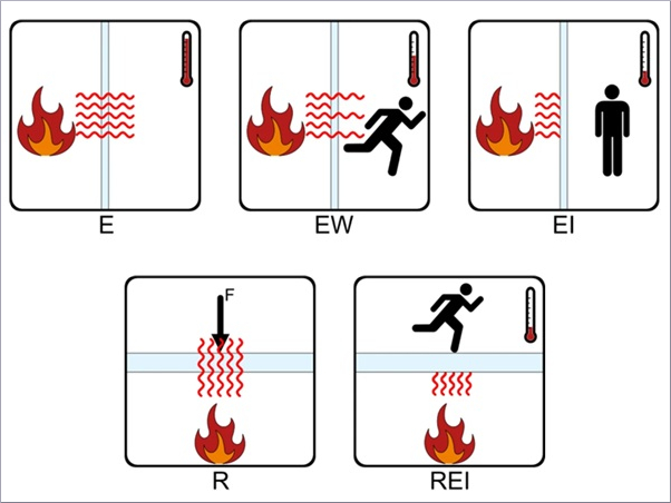
The Relay Building fire has demonstrated the fire hazard that curtain wall facades can pose to public safety and that such facades might require an added level of fire protection (passive or active), especially when used in high-rise buildings. In European building regulations, the requirement for curtain walls in high-rise buildings is limited to the provision of c.a. 1 m spandrel panels assembled with elements of E 30 class of fire resistance [3]. This requirement is not included in the UK regulations. Furthermore, both UK and European regulations limit the use of combustible materials. Although these measures are useful in reducing the probability of fire propagation and falling façade elements, further studies should be conducted to verify their effectiveness in different fire scenarios as previous experiments have shown that these measures will not be effective in many cases [4].
To identify what fire protection is optimal and what changes can be made to the system to increase its fire resistance, the thermal and mechanical behaviour of curtain walls in fire needs to be understood. Analysis from first principles would allow the most suitable protection measures to be defined for each specific structure (for example via performance based approach). However, understanding and predicting the fire behaviour of curtain walls is challenging because of the complexity of these facade systems [5].
A few experimental and numerical studies have been conducted to assess the fire performance of curtain wall systems. In 1999, the Loss Prevention Council conducted a series of experiments to study the failure mechanics of a full-scale curtain wall facade [6]. More recently, an experiment considered fire spread along a curtain wall with glass and aluminium composite panels and a curtain wall with masonry spandrel walls [7]. The authors reported fall-out of intact glass panels due to the deformation of the aluminium frame. A number of experimental studies have investigated the thermal performance of a curtain wall assembly heated uniformly (in a furnace) [[8], [9], [10]]. During these experiments, temperature measurements were collected, and in some cases, the deflection of the frame was also recorded [9].
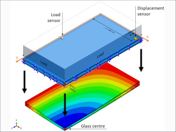
Finite element models have been developed to predict the static and dynamic behaviour of curtain walls [11,12]. Recently a model was developed to predict lateral deformations of glass facades during a fire [13]. The latter model utilizes a lumped mass assumption for heat transfer, defining a uniform temperature for each of the main elements (glass panel and aluminium frame). A more advanced thermal model was developed for an aluminium window frame [14]; however, the model was not verified with experimental data. To our knowledge, the thermal response of a curtain wall frame exposed to fire has not been systematically investigated.
This work therefore aims at rigorously investigating the thermal behaviour of the frame. The frame is the most vulnerable component of the system as it is made with thin aluminium profiles, includes polymeric sections that degrade a low temperature, and is directly exposed to heat during a fire. It is also the most critical component, as it carries the load of the glass panels to the main structure.
We propose a computational model that can capture the thermal response of a typical curtain wall frame exposed to fire. In Section 2, the computational approach is defined. In Section 3, the two experiments are described. The results section (Section 4) includes the validation of the model against the experimental data. In Section 5 we present a parametric study to identify the parameters that can be altered to improve the thermal performance and finally in Section 6 we investigate the effect of adding some thermal protection to the frame.
2. Curtain wall frame thermal model
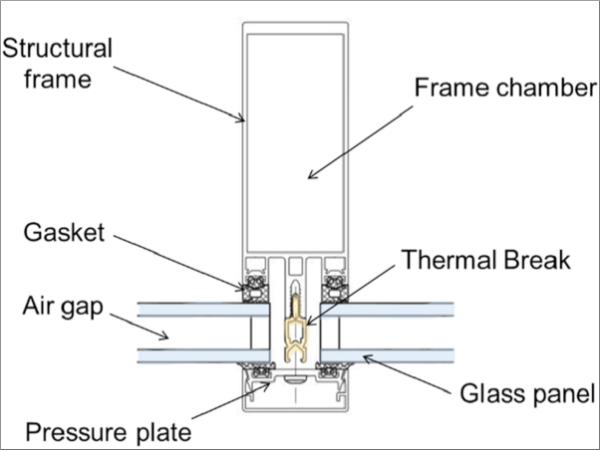
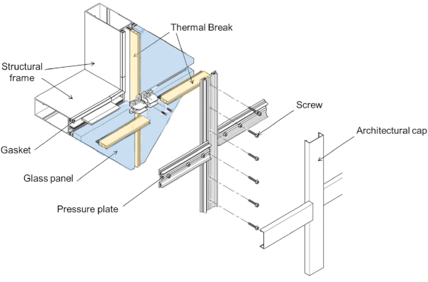
An accurate prediction of the frame's thermal response requires the characterization of the heat transfer across different components. There are two main systems for curtain wall that differ in the way they are assembled – the unitized system and the stick system. The stick system is assembled on site by screwing together the structural frame and the pressure plate (shown in Fig. 2) with the glass panel fixed in between these two components. At the screw connection a thermal break is inserted (highlighted in yellow in Fig. 2, Fig. 3). Wherease unitized systems do not require screws as they arrive on site pre-assembled. During the manufacturing process of the aluminium profiles, a continuous thermal break with high structural performance is embedded between the outer and inner profiles.
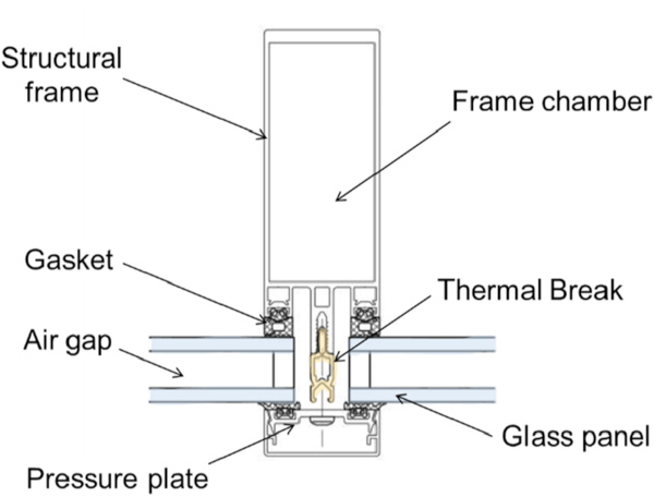
Thermal breaks are made of fibre reinforced plastics with low thermal conductivity, designed to create some resistance against the transfer of heat across the metal profiles and minimize heat losses during cold months. Thermal breaks must be considered carefully in a fire scenario as they will degrade at lower temperatures than the otherwise aluminium element, accelerating failure. Gaskets are used at the interface between the metal frame and the glass (Fig. 3), without gaskets the localized stress at the contact would cause the glass to shatter. It can be assumed that no heat is transferred to the glass as gaskets have very low thermal conductivity, and therefore the glass panels are not modelled.
The models proposed include conduction across the components of the framing system. The transient heat equation are solved numerically via the finite element model LS-DYNA. An implicit solver in respect of time is used. Perfect contact is modelled between each component and thus there is no thermal resistance between components. This is achieved in the model by defining components with shared nodes at the interface.
The bulk node feature [17] is used for convection and radiation in the frame chamber (see Fig. 3). The air convection within the chamber will cool down the frame whilst the radiation will facilitate the exchange of heat between the walls of the enclosure. We can calculate the convective heat transfer coefficient, h, within the rectangular chamber with Eqs. (1), (2a), (2b), (3) from Ref. [15].
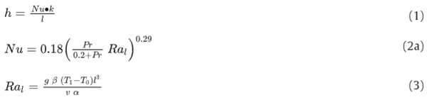
with Nu Nusselt number, Pr Prandt number and Ral Rayleigh number calculated via the air properties at ambient pressure: ν kinematic viscosity, α thermal diffusivity and β thermal expansion coefficient. Whilst l is the characteristic length and k the air conductivity and g the gravitational acceleration. 4.
We have selected the commercially available multipurpose finite element package LS-DYNA as it has been extensively used for structures and fire [16]. The software is powerful in solving simultaneously heat transfer and non-linear problems. It has been validated for radiation in an enclosure, required for solving the radiation in the frame chambers, and for various other 3D scenarios.
3. The partition wall and curtain wall experiments
The thermal response to fire of glazing frame systems has been investigated experimentally as part of two experimental programs that we will refer to as Partition Wall Experiments [18] and Curtain Wall Experiment [8]. The Partition Wall Experiments [18] involved the testing of different full-scale geometries of aluminium glazed partition wall to investigate their fire resistance. The partition walls were attached to a furnace and heated while temperature data was recorded. This is the only experiment that reports temperature evolution on both the exposed side (furnace side) and the unexposed side (ambient side) of the frame. The data is therefore very useful in our validation attempts as we can compare our predictions across the domain. Although the frame of a partition wall has a different geometry compared to a curtain wall frame, the systems share the main features. Both frames are made up of rectangular aluminium profiles connected via thermal breaks (Fig. 4). Similarly, to a unitized system, the partition wall frame does not include any screws.
![Fig. 4. Cross section of mullion of partition wall (left) and curtain wall (right). Dimensions in mm. Glazing highlighted in blue and thermal break in yellow. Figure adapted from [8,18].[8,18]. (For interpretation of the references to colour in this figure legend, the reader is referred to the Web version of this article.)](/sites/default/files/inline-images/Fig4_331.jpg)
The Curtain wall experiment [18] involved a stick system curtain wall heated via a furnace. For this experiment the same mock-up was tested twice, simulating first a compartment fire and subsequently an external fire (see Section 3.1). The temperature during heating was measured on the unexposed side only. The curtain wall mullion includes a thermal and screws spaced at 200 mm. These screws introduce a 3D component to the heat transfer and therefore a 3D model is required. Within the frame chambers an insulation insert is provided. The cross-section of both frame systems is shown in Fig. 4.
3.1. Boundary conditions
The furnace temperature (Tf) can be assumed to be uniform and follows one of the standard fire curves (standard fire or external fire) [19]. On the fire side (inside the furnace) the frame will be heated by radiation from the furnace walls, and convection from the hot gasses. The emissivity of the furnace is assumed to be equal to 1, while the heat transfer coefficient inside the furnace is taken as hf = 25 W/mK. On the ambient side (outside the furnace) the frame is cooling down by radiation and convection to the ambient air (Ta = 14°C), and the convective coefficient is set as ha = 4 W/mK. The boundary conditions are shown in Fig. 5.
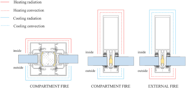
For the partition a 2D assumption was made due to the cross-section being uniform in the longitudinal direction as well as the boundary conditions. For the curtain wall this assumption is not possible as the screws are spaced at 200 mm and add a 3D effect to the heat transfer. For the curtain wall a compartment fire or an external fire will lead to heat travelling in opposite direction leading to different temperature and gradients within the frame.
3.2. Thermal properties
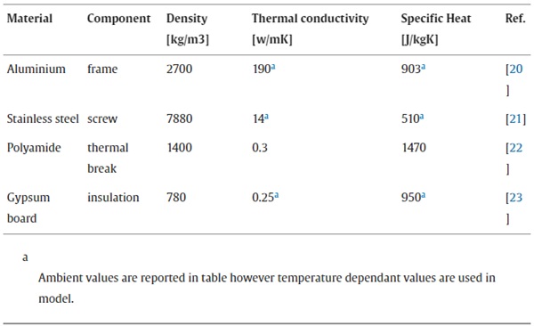
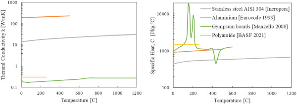
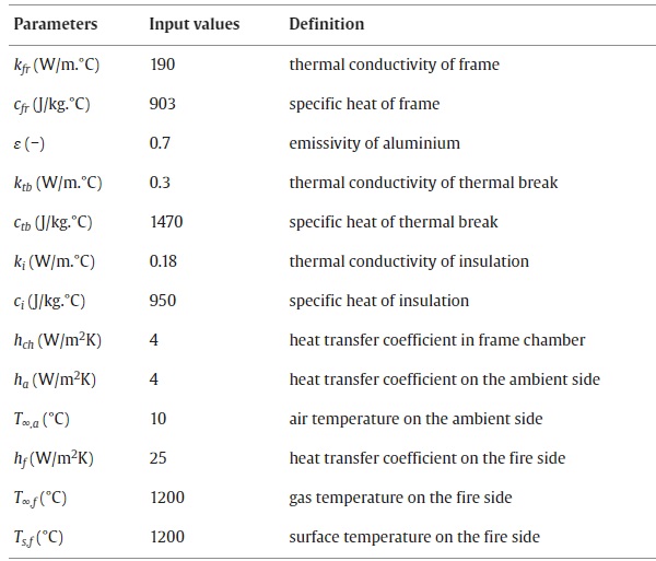
The thermal properties for the aluminium frame are taken from Ref. [20], temperature dependant conductivity and specific heat values for alloys 6xxx are used, whereas the density is assumed independent of temperature. The emissivity of aluminium was defined as 0.7 which is the value reported in Eurocodes for covered aluminium – this value was chosen as the frame will be quickly covered with soot from the fire. For the steel screw, conductivity and specific heat follow those for stainless steel AISI 304 [21], while the density of steel was assumed to be independent of temperature. Thermal breaks are assumed to be made of polyamide material with density, thermal conductivity, and specific heat temperature independent [22]. Where insulation inserts or insulation protection is present this was modelled as a gypsum board with temperature dependant conductivity and specific heat as reported in Ref. [23]. The thermal properties selected are summarized in Table 1 and temperature dependant values are plotted in Fig. 6.
Table 1. Thermal properties of materials in frame system.
4. Results
4.1. Partition wall experiment
The thermocouple readings from the partition wall experiment are compared with model predictions for the aluminium mullion in Fig. 7. The results show good alignment with the experiment on both the fire side (location P1) and the ambient side of the frame (location P2). For the temperature predicted on the fire side the correlations start to diminish after 28 min of heating (indicated with a vertical line in Fig. 7). Around this time the temperature of the thermocouple at location P1 experiences a steep increase which is probably caused by the flow of hot gasses inside the frame chamber. Once the section of the aluminium exposed to the fire reaches the critical temperature of 600 °C, we can assume that the aluminium has completely degraded (see gaps in Fig. 8). As the aluminium melts away the thermocouple starts recording the gas temperature. Thus we are not predicting the sudden increase in temperature at location P1 as we are modelling the aluminium temperature and we are not interested in temperatures above 600 °C.
![Fig. 7. Predictions of frame temperature compared to data recorded during the Partition Wall experiment [18] (left). Boundary conditions and position of thermocouples (right).](/sites/default/files/inline-images/Fig7_274.jpg)
4.2. Curtain wall experiment
The temperature predicted by the 3D model is compared with the experimental results from the Curtain Wall experiment described in Section 3. During the experiment, the curtain wall was exposed to a compartment fire and, subsequently, an external fire. Fig. 9 compares the temperature of the aluminium mullion for both experiments. The experimental data for the compartment fire shows a very steep increase in the temperature of aluminium at approximately 10 min of heating. This temperature increase was not reproduced by our model. At that time, it is expected that the gaskets sealing the joints between the glass and the aluminium frame will have completley degraded. In video recordings of the tests, we were able to observe the gaskets burning and being displaced around this time. The creation of gaps allowed the hot gases to escape from the furnace and reach the external side of the facade. Similarly for the external fire after approximately 30 min of heating the thermocouple start recording unstable temperatures, this again could be due to the breach of the sealing which allowed the gases to escape from the furnace to the outside.
![Fig. 9. Predictions of temperature of frame in compartment fire (left) and external fire (right) in comparison to experiments from Ref. [8]. The boundary conditions and thermocouple locations for each scenario are sketched.](/sites/default/files/inline-images/Fig9_205.jpg)
Gaskets are combustible and can ignite: however, make up a very small percentage of the overall mass and should not lead to severe negative effects in a fire scenario. These elements melt at very low temperature (130–270 °C) creating passage of hot smoke and gasses. Although their failure is not as critical as the failure of the thermal break, their influence on the heating of the frame is worth considering the gaskets when modelling the frame system.
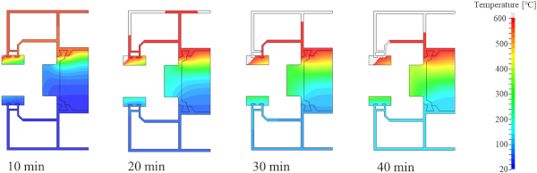
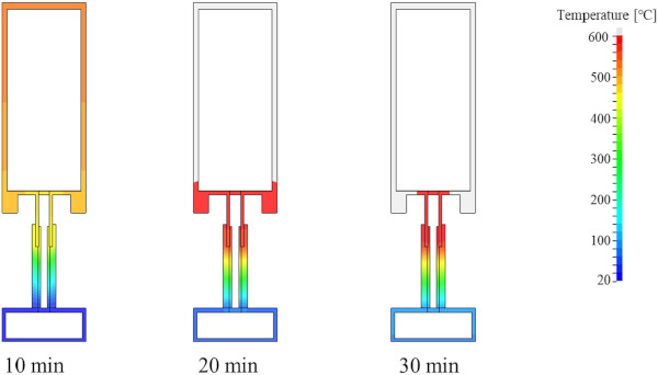
Thermal degradation of curtain wall frame predicted by our model is shown in Fig. 10. After 20 min of heating most of the structural frame will have reached the critical temperature for thermal degradation. The consumption of the structural frame, the load bearing element of the system, is a critical event as the stability of the system is not guaranteed.
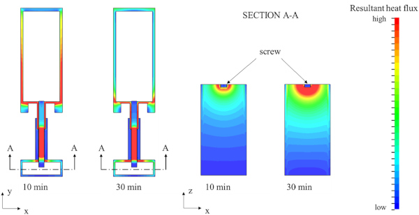
In Fig. 11 we compare the prediction of the 2D model and the 3D model with the experimental data from the curtainwall experiment. We can observe that the 2D model with the connector modelled as a steel screw is over predicting the temperature of the pressure cap while the 2D model with the connector modelled as a thermal break is underpredicting. The 3D model includes both the steel screw and the thermal break, and the predicted temperature are closer to the experimental data. We cannot ignore the effect of the steel screw as its acting as a heat sink, taking the heat away from the heated structural frame. The heat, once it has reached the pressure plate, will have a wider surface for cooling. The pressure plate is located on the ambient side of the curtain wall and will be exposed to ambient air. This effect is visible in Fig. 12.
![Fig. 11. Comparison of predictions of 2D and 3D models with data from Curtain wall experiment [8].](/sites/default/files/inline-images/Fig11_156.jpg)
5. Parametric study
To investigate which material and heating parameters have the greatest effect on the thermal response of the frame we performed a sensitivity study. The input parameters investigated are listed in Table 2 and their base input value is reported. We consider how each of these parameters affects two different model outputs. The first output that we consider is the time it takes for the exposed side of the frame to reach 500°, t500. At 500 °C aluminium will have lost virtually all of its strength. The second output parameter that we consider is the maximum temperature experience by the unexposed side of the frame after 40 min of heating, Tmax.
Table 2. Values of input parameters investigated in the sensitivity study.
We chose these output functions as they represent two critical scenarios: t500 is a proxy for how fast the heated section of the frame will degrade and by altering this parameter we can hope to reduce the time to failure of the frame. Tmax is crucial if we are interested in reducing the amount of heat travelling to the ambient side.
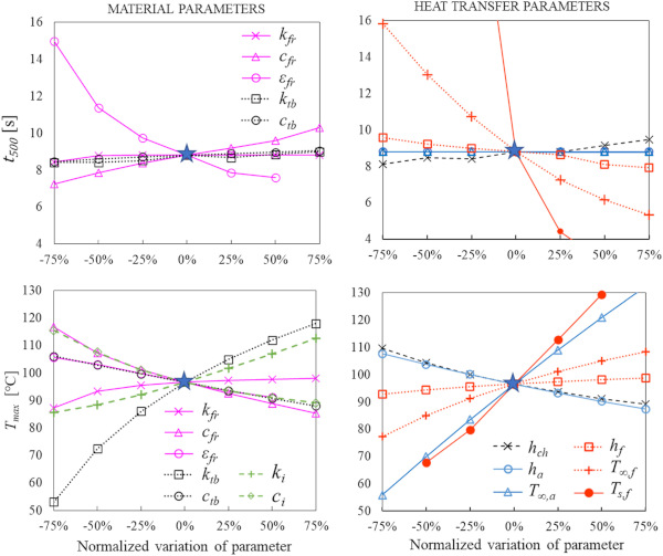
One-at-a-time analysis is the technique to quantify the sensitivity levels of different parameters. Two one-at-a-time (OAT) analysis approaches are used here: scatter-plot and sensitivity coefficient [24]. Scatter plot is a graphical sensitivity analysis approach, which can reveal how the output changes (increases or decreases) with the parameter of interest while the other parameters fixed at their base values. Fig. 13 is the result of scatter plot analysis. Every line displays how the simulated predictions changes with the variation of a unique. For the convenience of comparison, the variation of different parameters has been normalized and presented as a percentage change in respect of the base value.
The sensitivity coefficient is the derivative of output (y) with respect to the parameter of interest (X). Since the parameters compared here have different units, the dimensionless sensitivity coefficients S‾ is calculated by Eq. (2a), (2b) and Fig. 14.
![]()
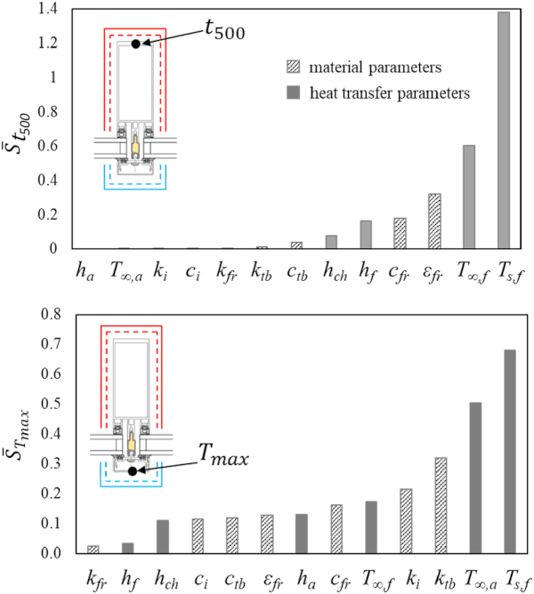
By comparing the sensitivity coefficients, we can define the parameter that can be changed during the design to have the greatest impact on the heating of the system. For example, changing the material used for the frame will have the greatest effect on the temperature experienced on the exposed side (see cfr and εfr). However, to reduce the heat transfer to the unexposed side, we need to change the thermal break (ktb) or insulation material (ki).
The temperature on the fire side (T∞,f and Ts,f) can be decreased with measures such as sprinklers and window drenchers; however, the effect of active protection is beyond the scope of this study and will not be discussed further. Such measures would be highly effective as has been demonstrated previously [6]. As shown in Fig. 14, the heating of the frame is extremely sensitive to the temperature of the fire, particularly when considering the heating of the exposed side.
6. Effect of thermal protection
As discussed in Section 5, if we want to modify the system to increase its fire performance, the most effective modifications will require either changing the material of the structural frame or reducing the fire temperature. As mentioned previously, we will not consider measures to control and reduce the intensity of the fire (e.g. sprinklers); however, we can control the heat received by the frame by adding some extra layers that shield it from the flames.
A typical curtain wall aluminum frame system was modelled, including a polymeric thermal break, insulation inserts, and steel screw connector. The simulation results indicate that failure due to thermal degradation of the aluminum frame is very rapid, occurring within the first 15 min of fire exposure for the ISO-834 standard fire. The thermal response of the standard frame was compared with that of a thermally protected frame. The frame was protected by applying a 10 mm gypsum board, essentially encapsulating the aluminium frame. The properties of the gypsum board follow those discussed in Section 3.2, and the emissivity was taken as 0.8 [23].
We also predicted the temperature of a frame assembled with different materials, namely carbon steel and stainless steel. The simulation predictions are shown in Fig. 15. The properties for stainless steel were defined in Section 3.2, for carbon steel we follow the utilise properties indicated in Ref. [25].
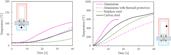
When considering the temperature experienced by the pressure plate, the most effective measure is to utilise a stainless-steel frame. Considering the temperature of the exposed side, the addition of thermal protection has the largest impact on the temperature of the frame. When thermal protection was present, the aluminium did not reach the critical degradation temperature during the heating phase. Carbon and stainless steel have high critical degradation temperatures, and their thermal degradation was not predicted. This indicates that curtain wall systems with steel profiles resist longer and provide a safer alternative to typical aluminium frames. However, materials are chosen not only for their heat transfer properties, and therefore might not be easily swapped, as there are other constraints that facade designers need address.
7. Conclusions
In this paper, we describe a computational model that can be used to analyse the thermal response of curtain wall systems exposed to fire, particularly focusing on the temperature experienced by the structural frame and the pressure cap, both of which are essential components for ensuring the stability of glass panels. The study explores the thermal response of two common curtain wall systems – the stick system and the unitized system – and validates the model against experimental data. The role of the screw connector and the thermal break are explored with regard to the thermal response.
The results of the sensitivity study indicate that changing the frame material and reducing the fire intensity will affect the temperature experience on the fire side of the facade. Whilst the temperature on the ambient side (not exposed to heating) is sensitive to the properties of the thermal break material. The model was used to investigate the response for an aluminium frame heated via a standard temperature time curve with and without thermal insulation and also to investigate a system with carbon steel and a stainless-steel frame. The results indicate that thermally protecting the frame or utilising a steel frame can prevent rapid thermal degradation.
The model presented can be used as a tool to advance our understanding of curtain wall frame fire behaviour and can be coupled with a model of the frame displacements to predict structural failure. Such tools can aid in the development of more effective fire strategies and resilient facade systems, ultimately enhancing public safety and minimizing economic losses due to fire incidents.
Declaration of competing interest
The authors declare that they have no known competing financial interests or personal relationships that could have appeared to influence the work reported in this paper.
Acknowledgments
This research was funded by the Engineering and Physical Sciences Research Council, Arup and the Society of Fire Protection Engineers.
Data availability
Data will be made available on request.


