
First presented at GPD 2017
In beam applications this is often achieved by bonding glass webs to glass fibre-reinforced polymer (GFRP) or steel flanges. However in glazing panel applications, e.g. vision panels of building envelopes, the need for transparency requires a swap in the position of these components: i.e. GFRP or steel core profiles are used to separate glass face sheets. Very limited research exists on the mechanical response of sandwich vision panels.
The objectives of this paper are to study their shear and post-fracture responses as a function of the core material and the adhesive employed for bonding core and face sheets. Four-point bending tests were performed on short-span GFRP-glass and steel-glass sandwich panels bonded with epoxy and acrylic adhesives respectively.
The deflections at collapse of both panels were large due to the progressive shear failure of GFRP profiles and the shear plasticity of the acrylic adhesive. Post-fracture capacities of more than 50% of the load at first fracture were achieved in all panels. Numerical modelling and a novel analytical tool are presented to evaluate the mechanical response of adhesively-bonded vision panels.
1. Introduction
Glazed curtain wall systems are made of insulated glazing units (IGUs) supported by rectilinear frames (e.g. metallic mullions spanning from floor to floor). The connection between the IGUs and the frames has a relatively low shear stiffness and therefore rotates independently of its substrates rather than bend with them – resulting in low shear transfer and low composite action between IGUs and mullions.
Glazed curtain wall systems are therefore function-separated layered systems: the structure (mullions) provides stiffness and load-bearing capacity, whereas the façade (IGUs) behaves as infill vision panels providing transparency and thermal insulation.
Despite the development of high-tech and high performance IGUs and support frames, the inherent function separation of the facade assembly produces structural inefficiency (reduced composite action), architectural constraints (visual obstructions and thermal bridges due to metallic mullions) and economic cost (nonprofitable indoor space occupied by large mullions).
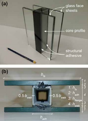
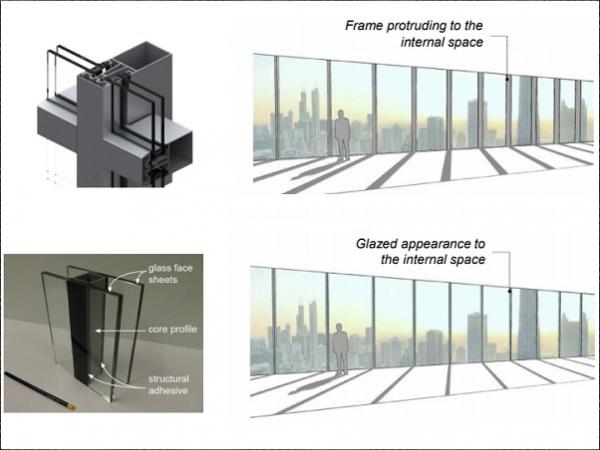
A slimmer, lighter and mechanically-efficient envelope system can be designed by merging façade and structure into a single composite component: a multifunctional sandwich vision panel. In this configuration the structural profiles are sandwiched in between and structurally bonded to fully toughened glass panes – see Figure 1a for a conceptual mockup.
The high shear stiffness of the adhesive layers and of the core profiles constrains them to bend together with the glass face sheets producing therefore high composite action in the system. The structural efficiency of this component provides an opportunity to reduce the overall depth of traditional curtain walls and therefore the core profile can be thinner and lighter than traditional mullions.
Weight can be further reduced by using glass fibre-reinforced polymer (GFRP) core profiles instead of metallic ones – and this has the additional benefit of reducing thermal bridges through the envelope due to the low thermal conductivity of the composite material compared to metals.
Bonding core profiles to outer glass face sheets is not a new idea. In the last decade, experimental investigation on the bonding of GFRP profiles to glass panes has been performed by Peters [1] and Wurm [2] – however very limited research on the modelling of the mechanical response was produced in these studies. More recently, extensive experimental work has been complemented with detailed analytical and numerical modelling at the University of Cambridge by Nhamoinesu [3] and Pascual et al. [4].
The objective of this paper is to present the salient research performed at Cambridge and illustrate the pre-fracture and post-fracture behaviour of GFRP-glass and steel-glass sandwich panels subjected to transverse (out-of-plane) loads. Four-point bending experiments are presented for short-span (460 mm) adhesively-bonded GFRP-glass (with epoxy adhesive) and steel-glass (with acrylic adhesive) panels. Analytical and numerical models to capture their mechanical response are presented.
2. Experimental investigation
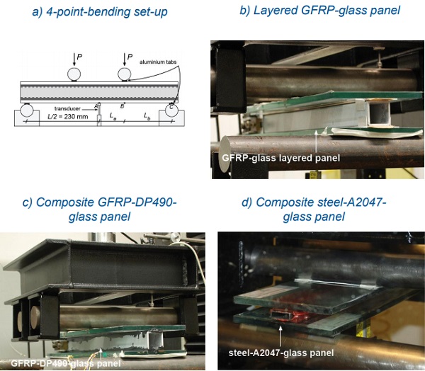
Two adhesively-bonded sandwich configurations were investigated: GFRP-glass (epoxy adhesive) and steel-glass (acrylic adhesive) composite panels – the former configuration has a GFRP pultruded core profile and the latter has a steel core profile. In addition a GFRP-glass layered sandwich panel was also investigated. The materials, four-point bending experimental set-up and experimental results of these panels are described below.
2.1. Materials and geometry of panels
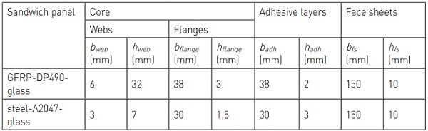
Seven sandwich panels were fabricated: three GFRP-glass composite panels, three steel-glass composite panels and one GFRPglass layered panel. The face sheets of all the panels consist of fully toughened sodalime-silica glass manufactured to BS EN 12150-2 [5] and measuring 150 x 500 x 10 mm3. The sandwich cores were made of a 500-mm length profile made of GFRP or steel and having a rectangular-hollow section. The GFRP pultruded profiles were produced by Exel Composites (38 x 38 x 3 mm3) and the mild steel E275 profiles were manufactured to BS EN 10305-3 [6] (30 x 10 x 1.5 mm3).
Epoxy adhesive DP490 from 3M (2-mm thickness) and Araldite A2047 from Huntsman (3-mm thickness) were used respectively to bond GFRP profiles and steel profiles to glass face sheets. In the following text the six composite panels are labelled according the core, adhesive and face sheet material, i.e. GFRPDP490-glass and steel-A2047-glass panels. The cross-sectional dimensions of the two composite sandwich panel configurations are given in Table 1 according to the geometrical parameters defined in Figure 1b – the layered GFRP-glass panel was identical to the GFRPDP490-glass composite panel except that the adhesive layers were replaced by low friction spacers.
![Table 2. Elastic and shear moduli (E and G) of the materials in the core, adhesive layers and face sheets in the two configurations of adhesively-bonded sandwich panels. Note: aproperties in the longitudinal direction (E) and core-web plane (G) as required for analytical modelling – orthotropic properties in other directions required for finite element modelling are given in Pascual et al. [4]](/sites/default/files/inline-images/Tab2_10.jpg)
The elastic and shear moduli, E and G, of the materials in all the panels are given in Table 2. The properties of the polymeric materials, i.e. GFRP and adhesives, exclude viscous effects and were estimated as follows: 1) for GFRP from burn-off and three point bending tests [4], 2) for adhesive DP490 from single-lap shear specimens (Figure 2a) [4], 3) for adhesive A2047 based on compressionrelaxation tests on adhesive cylinders (Figure 2b) [3] – the stress-strain laws adopted here for the two adhesives are shown in Figure 2c (the Poisson’s ratio of DP490 and A2047 are 0.38 and 0.43 respectively [3]). Unlike glass, steel and adhesives (all isotropic), GFRP is highly orthotropic and properties in Table 2 correspond to the pultrusion direction (E) and the core-web plane (G) – properties in other directions are given in previous work [4].
![Fig 2. Stiffness of adhesives investigated in (a) single-lap shear tests for DP490 (bonded areas of 50x25 mm2) [4] and (b) compressionrelaxation tests for A2047 [3], and (c) stressstrain laws adopted for the two adhesives.](/sites/default/files/inline-images/Fig2_43.jpg)
2.2. Experimental set-up
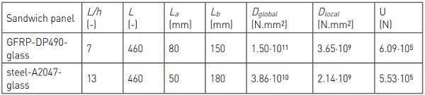
The shear response of the seven sandwich panels was evaluated in four-point bending tests. The span of all panels was L = 460 mm and the span-to-depth, L/h, were 7 (GFRPglass layered and GFRP-DP490-glass panels) and 13 (steel-A2047-glass panel). The loading configuration is shown schematically in Figure 3a and the values of the shear-span BC (La) and half bending-span AB (Lb) are given in Table 3.
The loads were applied on the panels by means of a 150-kN electromechanical testing machine (Instron 5500R) fitted with a steel load distribution frame which included two steel rollers (see Figure 3b to 3d).
The experiments were displacement controlled at a rate of 0.25 mm.min-1 (GFRP-glass layered and GFRP-DP490-glass panels, L/h = 7) and 0.5 mm.min-1 (steel-A2047-glass panel, L/h = 13) and performed at ambient laboratory conditions (23 ± 5 oC and 50 ± 10% RH) – low loading rates were selected to produce low strain rates and therefore avoid viscous effects in the polymeric materials of the panels, and to this end the loading rate was lower for the panels with lower span-to-depth ratio.
The applied loads, 2P, and the mid-span deflections, wA, were measured respectively by the 150-kN load cell fitted in the Instron machine and a LVDT transducer located below the bottom glass face sheet (see Figure 3a).
2.3. Experimental results
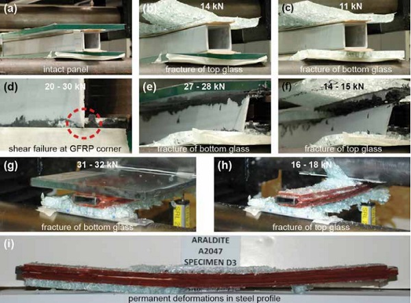
The seven 2P-wA experimental curves of the panels are shown in Figure 4a (GFRP-glass layered and GFRP-DP490-glass panels) and Figure 4b (steel-A2047-glass panel). The response of the GFRP-glass layered panel was linear up to the fracture of the top glass face sheet that occurred at about 14 KN (and 7-mm mid-span deflections) (see Figure 5a and 5b).
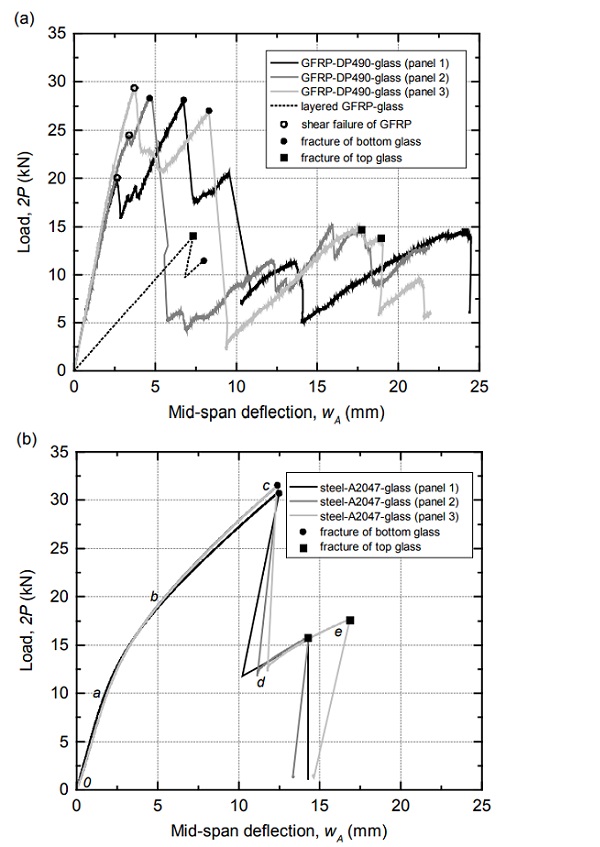
The resisted load abruptly reduced due to this fracture and then increased linearly in a reduced stiffness path up to about 11 kN (and 8-mm mid-span deflections) that produced the fracture of the bottom glass face sheet (see Figure 5c). The stiffness and load-bearing capacity of this layered panel were significantly outperformed by the three GFRP-DP490-glass panels. The response of these composite panels was almost linear up to loads between 20 kN and 30 kN (and at mid-span deflections of around 3 mm) that produced the longitudinal shear failure of the pultruded core profiles close to the supports (see Figure 5d).
The resisted loads reduced due to the local shear failure of the profiles and then subsequently increased on a reduced stiffness path to around 27 kN producing the fracture of the bottom glass face sheets (Figure 5e). This fracture produced an abrupt reduction in the resisted loads. As the loads subsequently increased on a significantly reduced stiffness path up to around 15 kN, the top glass face sheet fractured (Figure 5f) – corresponding mid-span deflections were of around 17 mm to 24 mm.
The three 2P-wA experimental curves of steelA2047-glass panels exhibited a linear response (0a in Figure 4b) up to about 2P = 10 kN and 2-mm mid-span deflections. Then the curves exhibited a significant non-linearity (ab) between 10 kN and 20 kN indicating a relevant reduction in the stiffness of the panels which was attributed to adhesive plastification. An almost linear response (bc) was then observed up to about 31 kN that produced the fracture of the bottom glass face sheet – corresponding mid-span deflection were of about 12.5 mm (Figure 5g).
The resisted loads reduced abruptly due to this fracture (cd) and subsequently increased on a reduced stiffness path (de) up to about 16 kN to 18 kN producing the fracture of the top glass face sheet (see Figure 5h) and corresponding to midspan deflections of about 14 mm to 17 mm. After the failure of both face sheets a residual deformation was observed in the core profiles indicating plastic deformations in the steel material (see Figure 5i).
3. Modelling
In this section the load-deflection responses (2P-wA curves) of the un-fractured composite panels were modelled numerically (finite element models) and analytically (solutions developed by Pascual et al. [4]) and the predictions were compared to the experimental results.
3.1. Numerical
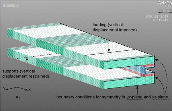
Three-dimensional finite element models of the four-point bending experiments on the GFRP-DP490-glass and steel-A2047- glass panels were developed using Ansys Mechanical APDL v16.2 software. The geometry of the panels, i.e. spans and crosssection dimensions, are defined in Tables 1 and 2 – only one quarter of the panels were modelled as the panels are by-symmetric (Figure 6). A fine mapped orthogonal meshes of SOLID45 elements was adopted – details on the meshing criteria can be found in Pascual et al. [4].
The strain-stress responses of the materials were considered as: linear elastic (for glass, GFRP and adhesive DP490), elastic perfectly plastic (for steel, i.e. yield stress of 275 MPa) and trilinear elasto-plastic (for adhesive A2047 as shown in Figure 2c). The numerically predicted 2P-wA curves of the panels are shown in Figure 7 together with the experimental results (un-fractured state).
For the GFRP-DP490-glass panels, the numerical prediction was linear and showed an excellent matching of stiffness (slope of the curves) with respect to the tested panels. For the steel-A2047-glass panels, the numerically predicted response was highly non-linear largely due to the non-linearity of the adhesive response.
Up to 2P = 20 kN, the stiffness obtained in the numerical simulation matched well with the test results, however above this load the numerical response underestimated the stiffness by about 35% - which indicated that the adhesive stiffness at large strains (considered here as EA2047 = 0 MPa) may have been underestimated.
3.2. Analytical
A novel analytical model for predicting the deflections and strains produced by fourpoint bending loads on adhesively-bonded sandwich panels (with thick face sheets and shear-deformable adhesive layers and cores) was recently developed by Pascual et al. [4].
This model considers that all materials behave linearly and that the structural response of the panel result from the contribution of two mechanisms: 1) a local response in which cross-sections of the core and face sheets bend about their respective centroidal axes, and 2) a global response in which the sandwich cross-section bends as a whole about the global centroidal axis. Shear deformations are also associated to these mechanisms and the geometrical compatibility of bending and shear deformations depends on a mechanical parameter, a2, relating shear stiffness to bending rigidity and is given by [4]:
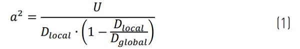
where Dlocal and Dglobal are the flexural rigidities of the local and global mechanism respectively and U is the shear stiffness of the sandwich panel – the values of these mechanical properties for the two configurations of composite panels presented in this paper are given in Table 2.
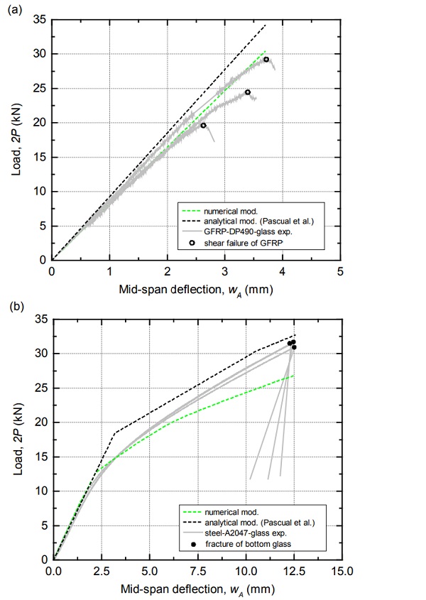
The analytically predicted 2P-wA curves for the composite panels studied here are shown in Figure 7. For the GFRP-DP490-glass panels, the predicted response was linear and matched well with the experimental results – experimental stiffness was overestimated by about 10%. For the steel-A2047-glass panels, analytical predictions were more complex to calculate because the adhesive response was trilinear (see Figure 3a).
The analytical model was therefore applied in three independent stages as a function of the average shear stress in the adhesive layer across the shear-span BC: 1) EA2047 = 543 MPa was considered until an average shear stress of 10 MPa was reached in the shear-span, 2) EA2047 = 44 MPa was then considered up to an average stress of 12.5 MPa and 3) EA2047 = 0 MPa was then considered.
The predicted response was essentially bilinear and was in good agreement with the experimental results although the gradual decrease of stiffness for 10 kN < 2P < 20 kN could not be captured analytically (see Figure 7b). This result indicates that the response of the tested panels may have been governed by a bilinear response of the adhesive (EA2047 = 543 MPa and EA2047 = 44 MPa with plastification at about 10 MPa shear stress) and that EA2047 = 0 MPa may have not been reached during the experiments.
4. Discussion
The sandwich configuration presented in this research produces composite glass panels with high levels of robustness and load-bearing capacity: the deflections at collapse obtained here were 5 times higher than those at first failure of GFRP core profiles (about 3 mm) or at first plastification of A2047 adhesive (about 2 mm) and collapse loads were significantly high and more than 50% of the maximum capacity of the panels (see Figure 4).
In addition the sandwich configuration presented in this paper generates the composite action between the structural glass face sheets and therefore achieves high levels of structural stiffness in the panels. The composite action in terms of deflections, η, can be defined as:
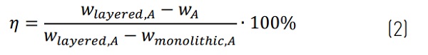
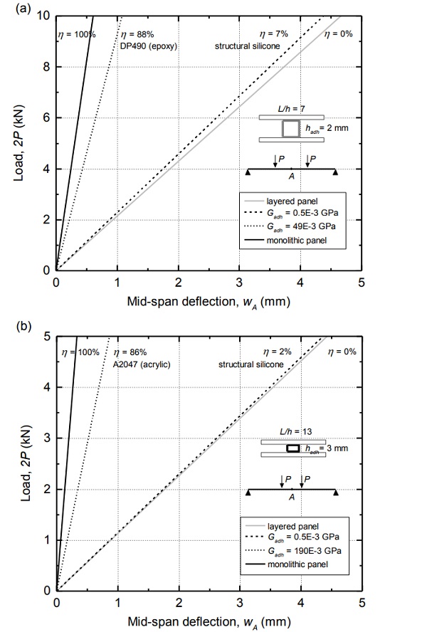
where Wlayered,A and Wmonolithic,A are respectively the mid-span deflections that would be obtained if very shear-flexible adhesives, i.e. Gadh → 0 (layered panel), and shear-rigid adhesives, i.e. Gadh → ∞ (monolithic panel) were employed and wA is the mid-span deflection obtained for the particular adhesive (shear modulus Gadh) for which the composite action is investigated. According to equation 2, and applying the novel analytical model to predict deflections [4], the adhesives used in this study have generated a composite action, η, in the order of 90% and outperform structural silicones (2% < η < 7%, see Figure 8).
From the analytically predicted response of steel-A2047-glass panels, it has been inferred that the adhesive response in the tested panels might have been essentially bilinear – instead of the trilinear material law obtained in the tests performed in adhesive cylinders (see Figure 2b).
This can be attributed to the confinement of the adhesive in the panels (together with its high Poisson’s ratio of 0.43) which may have prevented the second plastification ramp (EA2047=0MPa) and may have produced a sustained elastic modulus of about EA2047 = 44 MPa for strains above 0.075. Research is still in progress concerning the mechanical response of the structural adhesives employed in this research as well as models to capture the progressive failure of adhesively-bonded sandwich panels.
5. Conclusions
Novel glass components combining structure and façade into a single sandwich panel have been tested under four-point bending loads and have been numerically and analytically investigated. The following conclusions were obtained:
-Sandwich structures made of structural glass face sheets separated and structurally bonded to composite or metallic core profiles produce stiff and strong vision panels. The stiff structural adhesives used in this study activate composite actions (in terms of deflections) of about 90% and outperform structural silicones.
- Deflections at final collapse of the composite panels were of at least 5 times higher than those at first failure and collapse loads were about 50% of the maximum capacity of the panels indicating robustness in the sandwich configuration.
- A numerical and a novel analytical model have been successfully used to model the responses of the composite panels. To improve further the accuracy of the models and capture also the post-fracture behaviour, research has to be done concerning the non-linear response of adhesives and the fracture of glass in the proposed sandwich configuration.
References
[1] Peters S. Kleben von GFK und Glas fur baukonstruktive Anwendungen [PhD Thesis]. Germany: Universitat Stuttgart; 2006.
[2] Wurm J. Glass structures: design and construction of self-supporting skins. Basel: Birkhauser; 2007.
[3] Nhamoinesu S. Steel-glass composite panels [PhD Thesis]. UK: University of Cambridge; 2015.
[4] Pascual C, Montali J, Overend M. Adhesivelybonded GFRP-glass sandwich components for structurally efficient glazing applications. Compos Struct 2017;160:560-573.
[5] BS EN 12150-2. Glass in building – thermally toughened soda lime silicate safety glass (part 2). London: British Standards Institution; 2004.
[6] BS EN 10305-3. Steel tubes for precisionapplications – technical delivery conditions (part 3). London: British Standards Institution; 2002.


