Authors: Vlastimil Hotar, Ondrej Matusek and Jan Svoboda
Source: MATEC Web Conf., 89 (2017) 01007
DOI: https://doi.org/10.1051/matecconf/20178901007
Abstract
Glass is reflective in large angles of incidence. Using this property for the detection of shapes is the basic goal of the research. The detection of 2D shapes from flat glass is a relatively simple example that has been used at the beginning of the research. The detection is based on three steps: capturing an object in large angles of incidence, inclusion distortion and other optical defects of the scan, and a reconstruction of the shape.
1 Introduction
Vision systems for monitoring and control in the glass industry are applied especially for quality monitoring of container glass wares, window glass and automotive glass. The possibilities of the vision system applications in the glass industry are mostly: counting products, measurement and quality production monitoring, shape recognition, positioning and production monitoring and control using feedback. Despite an intensive investigation of machine vision for several decades, this is still a large field of research for solutions to some specific problems because glass has special properties [1]. The major problem is the transparency of colorless glass.
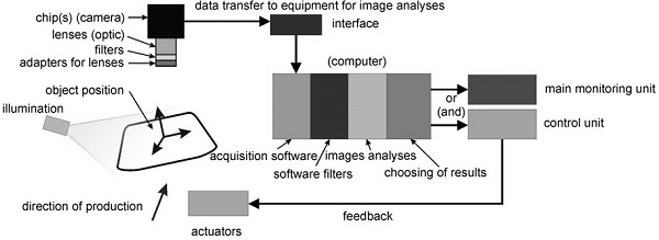
The systems have different requirements for monitoring glass melt and cold glass semi-finished or final products. The typical and general scheme of monitoring and/or a control system is in Figure 1. Not all equipment mentioned in the figure must be used for the analysis of data from production.
The system generally consists of specific parts and for applications in glass production has some specific requirements:
- suitable tape of illumination must be chosen for scanning transparent materials (area array, backlight, ring illuminator, dome illuminator, diffuse light illuminator, multi-axis illuminator, polarized illuminator);
- position of an object must correspond with illumination;
- adapters for lenses can be used instead of (or with) illumination for better visibility of the object (polarisation illumination adapter, coaxial vertical illumination adapter, diffuse illuminator adapter, ...);
- filters can be used for the separation of some wave lengths from acquisition images;
- lenses (optic);
- chip(s) (camera), on the basis of the production process (line or area scan camera) and a required resolution (frame rate, resolution in pixels, colour, spectrum, ...);
- data transfer to equipment for image analyses (cables, A/D convector);
- interface (e.g. IEEE 1394, camera link, channel link, GigE vision, ...);
- acquisition software;
- software filters, important for the next process;
- image analyses [2], choosing fast and optimal analyses is important;
- choosing results;
- data transfer to the main monitoring unit or a control unit (connected by feedback to actuators);
- thermal insulation and cooling, important in the case of glass melt monitoring.
The research at the Department of Glass Producing Machines and Robotics is focused on analyses of structured images using fractal dimension [3]. The data have a character of digital images and obtained dividing lines (e.g. profiles [4], roughness and the dividing line of light and shadow). The analyses are applied for example in corrugation that uses a reflection of zebra plate [5]. The idea to use reflection for the detection of glass objects comes from this application.
2 Glass reflection
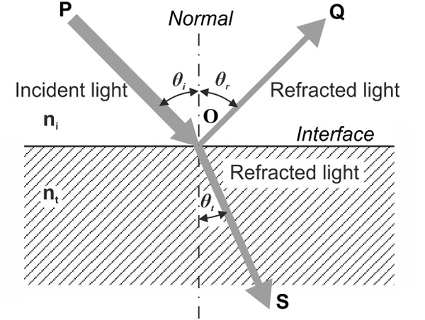
When light moves from a medium of a given refractive index ni(air) into a second medium with refractive index nt (glass), both reflection and refraction of the light may occur [6]. In Figure 2, an incident light ray PO strikes at point O the interface between two media of refractive indices ni and nt. Part of the ray is reflected as ray OQ and part refracted as ray OS. The angles that the incident reflected and refracted rays to the normal of the interface are given as i, r and t. The relation between these angles is given by the law of reflection:
![]()
and Snell’s law:
![]()
The fraction of the incident power that is reflected from the interface is given by the reflectance R and the fraction that is refracted is given by the transmittance T. The amount of light reflected from the material under normal incidence (angle of incidence θᵢ≈θₜ≈0) is proportional to the square of the index change at the face:
![]()
For common glass in air, nᵢ = 1 and nₜ = 1.5; thus about = 4% of light is reflected. Note that reflection by a flat glass is from the front side as well as the back side, and that some of the light bounces back and forth a number of times between the two sides. The combined reflection coefficient Rg for this case is
![]()
when interference can be neglected, Rg = 7.7 %. However, the reflection is for the intended detection insufficient, and illumination at a high angle must be used.
The calculations of R and T depend on the polarization of the incident ray. Using the Fresnel Equations (after simplifying) the equations for light polarized with the electric field of the light perpendicular to the plane of the diagram in Figure 2, the reflectance R⊥ is given by:

If the incident light is polarized in the plane of the diagram, the Rǁ is given by:

Using the Snell’s law (2) the equations:
![]()
the R⊥ and Rǁ are completely derived by θᵢ. If the incident light is unpolarized (containing an equal mix of perpendicular and parallel polarizations), the reflection coefficient is
![]()
The dependence of reflectance on the angle of incidence is in Figure 3.
As a consequence of the conservation of energy, the transmittance in each case is given by
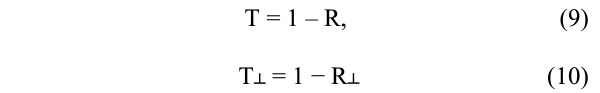
and
![]()
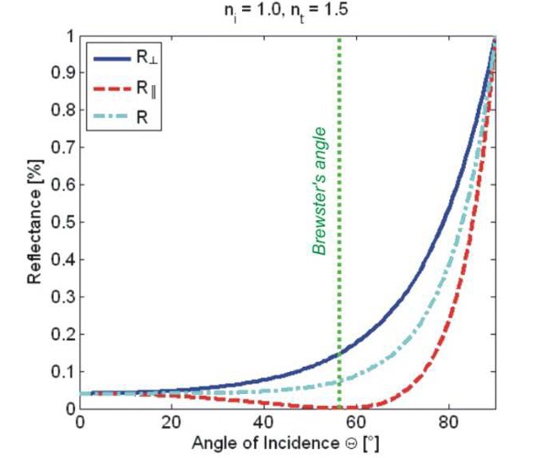
Figure 3 shows that glass is reflective in bigger angles of incidence (θᵢ ≥ 70° for R and R⊥). Furthermore the reflectance depends on the polarization of incidence light; it is higher with the electric field of the light perpendicular. In the case of incident light being polarized in the plane (parallel), the reflectance R degreasing to the Brewster's angle, when the light is perfectly transmitted through the surface. Then the reflectance rises. The Brewster's angle is defined:
![]()
and for the plane glass surface θBg = 56.31°.
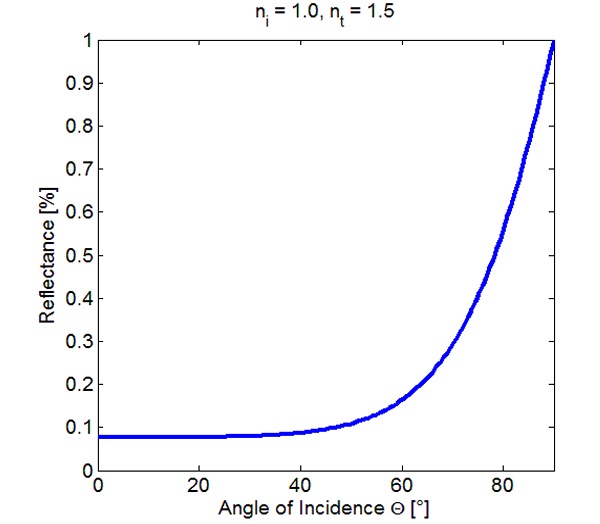
For the real measurement is the combined reflection coefficient Rg important, because of flat glass and reflection is from the front side and the back side. Using equation (4) the graph in Figure 4 is obtained for unpolarized light.
3 Detection of Flat Glass Shapes
The reflection under high angles of incidence can be used for the detection of an object on a black, non-reflective and matt background. The angle of incidence should be selected on the basis of the function in Figure 4. Obviously, the reflection does not dramatically change till the angles of incidence 40° (8,6 % of reflectance, 7.7 % for the normal incidence). The reflectance is double for the angle 58,7° and triple for the angle 66,2°. If the higher reflectance under the high angle of incidence is used for the detection of glass, the angle must be minimally 60°.
The reflectance can be increased using perpendicular polarised lighting (Figure 3).
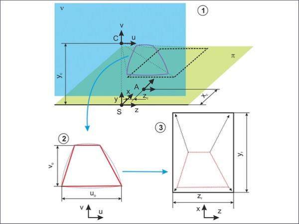
The detection is based on three steps, Figure 5:
- capturing an object in a large angle of incidence using a standard CCD or CMOS camera and an object-lens and obtaining of object contours,
- recomputing the captured object including distortion and other optical defects of the scan and
- reconstruction of the captured shape including perspective.
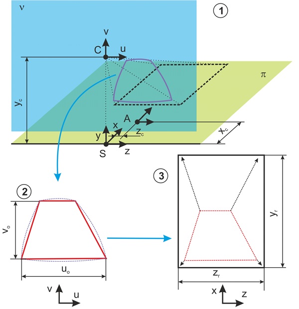
The first two steps are commonly used in machine vision and image analysis. The third step has to be solved for the observed object. In the case of flat glass, the one-point perspective is used. Before starting the detection a pre-set must be done for the final detection. The per-set is a measurement with a ruler (an etalon), which defines relations (scale) between a captured space (in millimeters, axes x, z) and an image (in pixels, axes u, v). The position of the camera (the focal point of object-lends, xc, yc ) and the axes start (A: xc, zc) must be also defined.
3.1. Experiment
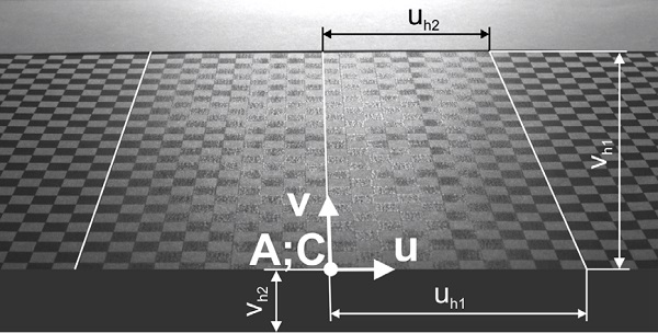
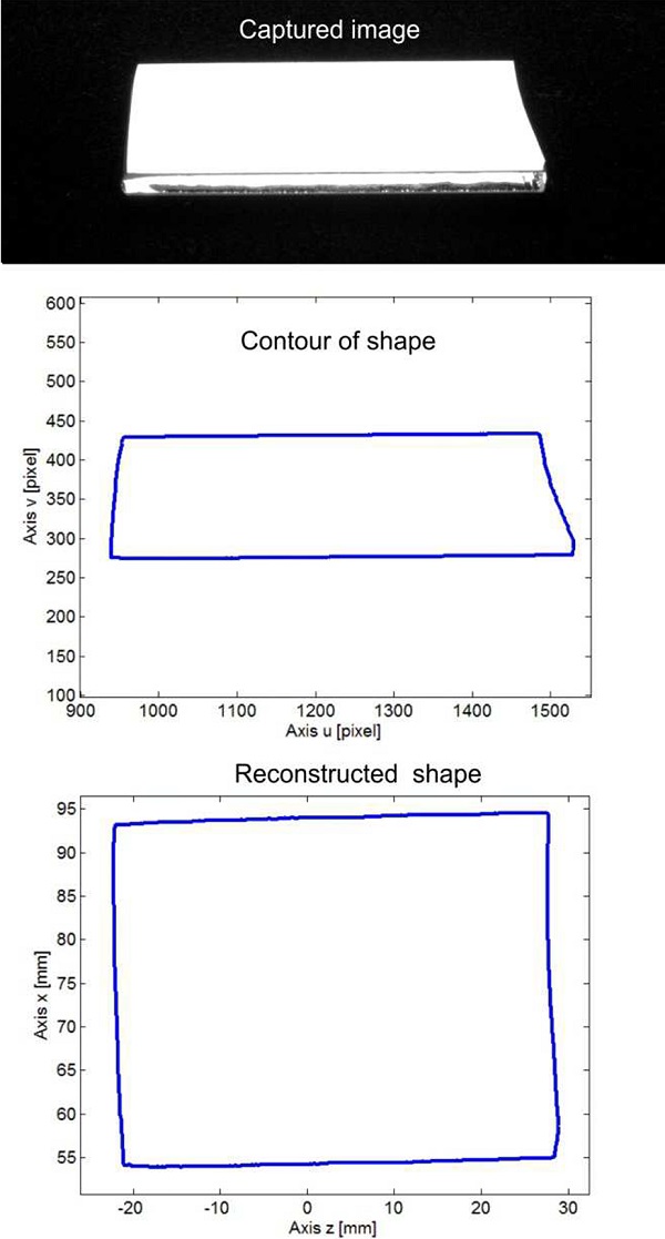
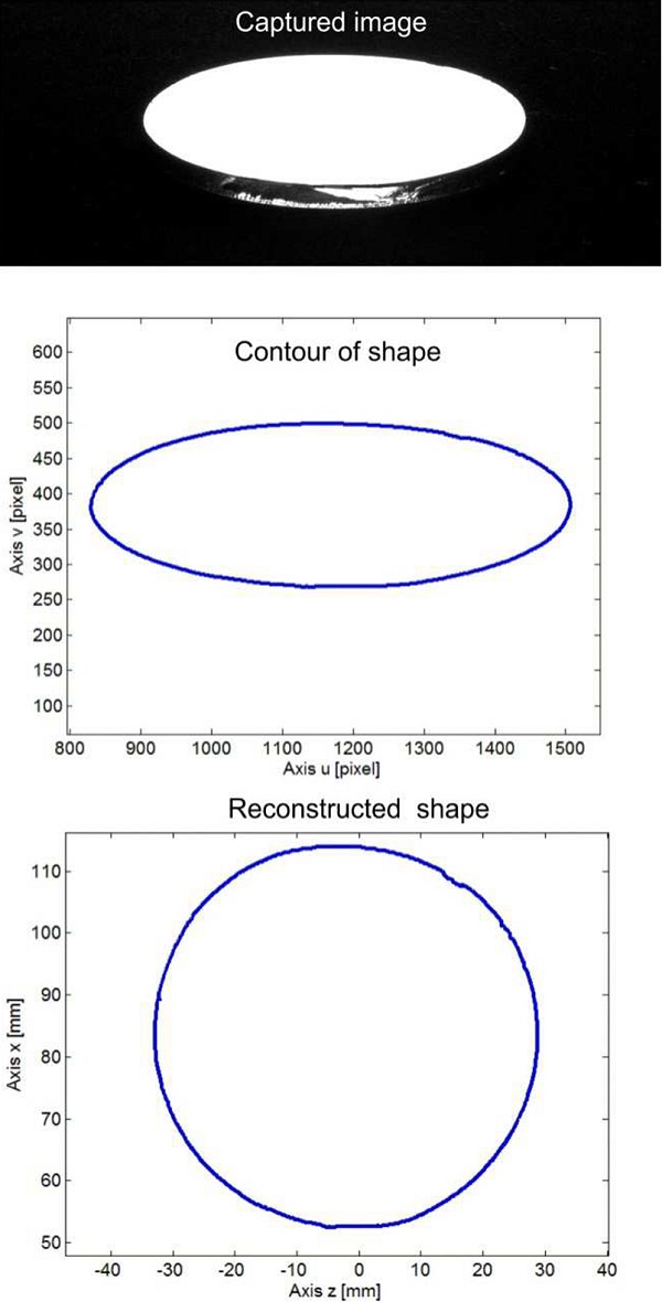
Simple shapes were used in the experiment: circle (diameter 61 mm) and rectangle (length 50, width 40 mm). A chessboard with an edge of squares 5 mm was used for pre-set of the scale, Figure 6 and the basic relations for the conversion were defined. The position of the camera and the axes start were measured, Figure 7.
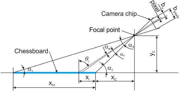
The functions for the reconstruction were derived, from the known measurement in pixels (axis u, v) to the real measurement in millimetres (axis x, z):

where xᵢ is real position measured point in x axis in millimeters (axes start at the point A), vᵢ is the position of the point in axis v at image in pixel (axes start at the point C, where A≡C), yc and xc are known, α₂ can be easily determined,
![]()
and
![]()
For axis z can be determined the equation:

where zᵢ is the real position measured point in z axis in millimeters, uᵢ is the position of the point in axis u at image in pixel, zₕ₁ is the length of the chessboard in millimeters corresponding to length uₕ₁ measured in pixels, both are known, the horizon is defined

where uₕ₁, uₕ₂ and vₕ₁ are obtained from the measurement from the chessboard image, Figure 5.
3.2. Results
Figures 8 and 9 show the steps and results of the reconstruction.
3.2 Discussion of results
The first analyses were focused to verify the possibilities of the methodology and also to develop a software tool (in Matlab), hence the analyses were applied without the distortion of lens-object. The results are not perfect in accuracy and during the experiment problems were found that must be solved in the next research, such as:
- accuracy in the definition of the focal point,
- quality of the diffuse light,
- definition of the scale,
- inclusion of distortion and other optical defects.
In the next research effect of changed parameters has also to be defined, such as:
- polarization,
- intensity of lighting,
- surrounding and parasite illumination,
- setting of a camera (with respect to necessary depth of field ),
- properties of a black, non-reflective and matt background,
- dependence of the reconstruction accuracy on an angle of incidence.
4 Conclusion
The goal of this part of the research was to specify theoretical basic properties for the detection of glass using reflection under the high angles of incidence, to develop the software tool, to verify the possibilities of the methodology, and to specify problems and steps for the next research.
The angle of incidence must be higher than 60°, optimal should be using the perpendicular polarised lighting, the equations for reconstruction were derived, the software tool was developed and was verified with experiment. The problems of the present approach and next the steps were specified.
The final target of the research is to specify conditions and a potential for the 3D analysis of formed flat glass like automotive one.
Acknowledgments
This work was supported by the grant of Students grant contest of the Technical University of Liberec, number SGS 21006/115, which uses special-purpose support for university research and is financed by the Ministry of Education, Czech Republic.
References
- V. Hota, Monitoring of Glass Production Using Vision Systems. In: 9th ESG Conference, Zurich: Trans Tech Publications Ltd. p. 511-516, (2008)
- M. Sonka, V. Hlavac, R. Boyle, Image Processing, Analysis, and Machine Vision. Pacific Grove: Books/Cole Publishing Company, (1998)
- B.B. Mandelbrot, The fractal geometry of nature, New York: W. H. Freeman and Co. (1982)
- A. Hota, P. Kratochvíl, V. Hota, The Corrosion Resistance of Fe3Al Based Iron Aluminides in Molten Glasses. Kovové Materiály - Metallic Materials, p. 247-252, (2009)
- V. Hota, F. Novotný, H. Reinischová, Objective evaluation of corrugation test. Glass Technology: Eur J Glass Sci Technol Part A., Vol 52, No 6, 197202 (2011)
- E. Hecht, Optics. 4th Edition. San Francisco: Pearson Education, Inc., (2002)