First presented at GPD 2017
The structural system consists on one hand of a glazed steel frame with four stanchions rigidly fixed to the base plate and connected by four transoms at the top and on the other hand of two laterally glass attachments. These are made of vertical load-bearing glass walls and a horizontal glass roof, which are connected among each other by structural sealants.
Together with an anchor profile that is completely hidden in the joint gap, the glass elements are also acting as bracing elements. Specifications of the building authorities called for a structural concept of the pavilion’s glass attachments for different states of destruction.
In addition extensive requirements had to be fulfilled to obtain a special building permit for the structural sealants. The project is an outstanding example for the possibilities in constructing with glass. It combines the structural features of a load bearing all glass building with state-of-the-art joint techniques.
General
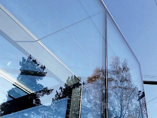
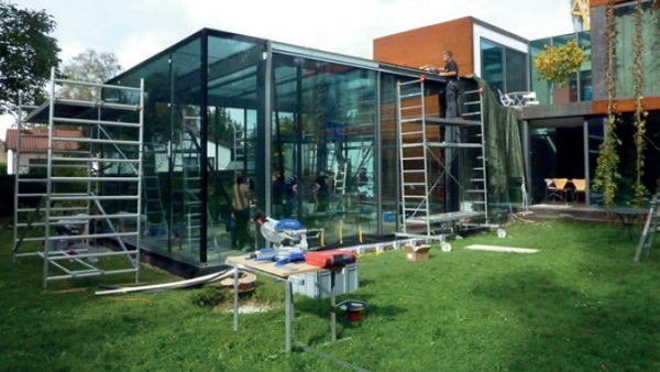
In early 2015, a cuboid pavilion with glass walls and glass roof was completed in the northeast of Munich. It is a free-standing extension of a single house to the garden. The pavilion can be both garden side accessed through large sliding glass elements, as well as from the main building by a short walkway. The building is 8.6 m long, 5.8 m wide and 4.2 m high. It was designed by the owners Hildegard Rasthofer and Christian Neumaier. The latter was also responsible for the execution.
The structure
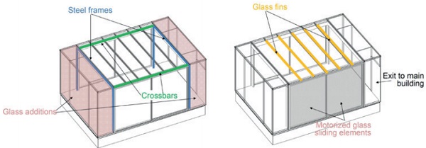
Two steel frames made of welded rectangular tubes are connected with crossbars in the corners and form the core of the structure. The four columns are connected rigidly via anchor plates and steel anchors with the floor slab made of reinforced concrete. The main axes of the steel frames are each offset by about 1.25 m from the short sides of the building inward.
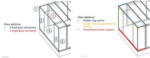
In these areas glass walls and roof glazing form self-supporting building envelopes (the additions) attached to the steel structure. Both consist of one roof panel and four wall panels respectively. In the wallroof joint a ring anchor of stainless steel is hidden, which firstly embraces the roof panel and bears it horizontally. Secondly it serves as a mechanical securing for the glass walls against wind suction.
The walls between the steel frames are made of floor to ceiling, motorized glass sliding elements. The roof panels are supported in this area by glass fins.
The glazing
The fixed glass wall panels consist of a 77.5 mm thick 3-pane insulated glass unit (IGU) having inside a laminated safety glass (LSG) from twice heat-soaked fully tempered glass. The latter takes over the functions of a primary load-bearing structure:
Bearing the vertical loads from the supported roof panes
Working as a bracing element for horizontal loads in case of failure of another panel
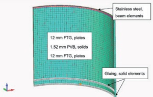
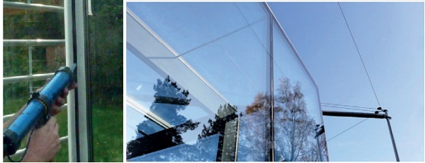
The largest glass wall is about 3 meters wide, 4 meters high and weighs more than two tons. The fixed vertical glazing is mounted conventionally on the lower edge and glued to the roof panel on the top edge via structural sealant. The joints between the wall panels are also sealed with silicon.
The 5.4 m long and up to 1.3 m wide roof panels also consist of 3-pane insulated glass units. The bottom layers are laminated safety glass made of heat strengthened glass. In case of the glass additions, these act together with the ring anchors as horizontal bracing elements. Only here the edges of the horizontal glazing are structurally bond to the wall panels. The other edges are fixed mechanically by pressure plates.
The LSG-glass fins are only 280 mm high with a length of 5.35 m and consist of four layers of heat-soaked fully tempered glass. Their ends are each seated in a steel socket welded to the cross bar, which serves as a non-displaceable and torsional stiff support. A U-profile is bond to the top edge of the fins and forms the basis for a metal channel in which the screws of the roof pressure plates are anchored.
Structural sealant glazing
In this construction, two types of structural bonding can be distinguished, also with regard to place of manufacture:
Edge seal of insulating glass units: Factory bonding
Assembling of the different IGUs: On site bonding
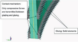
In the IGU factory bonding of the individual layers in the glass edge seal took place using Dow Corning’s structural silicon DC 993. Because the top and vertical edges of the glass walls are not braced by pressure plates, the sealant is stressed by wind suction and pressure differences between air space and atmosphere. Because the individual layers were supported vertically on the bottom edge by plastic blocks, no shear forces have to be considered from the dead load.
First, the glass walls were erected and aligned on site. Thereafter, the ring anchors and roof panels were placed. The joints between ring anchors and glass were sealed with structural two-component silicon DC 993, too. The joints were designed for the resultant of wind suction and dead weight of the roof panel according to ETAG 002.
Rules and regulations
For the construction project a special building permit had to be obtained. The bonds are different from the currently valid general building approvals for structural sealant glazing systems. In addition, there are glass walls and glass fins outside the field of application of current German standard DIN 18008.
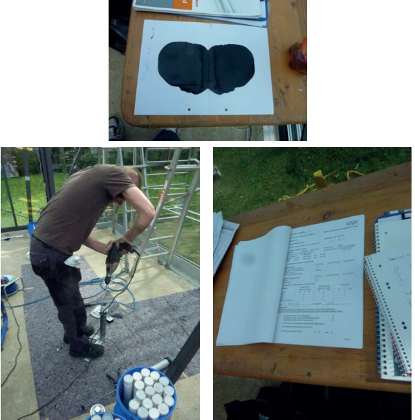
In two expert opinions that have been used as a basis for granting the special building permit, the respective differences were evaluated. For the structural bonding in the edge seal of the insulating glass panes, a certificate of conformity was demanded on the basis of a factory production control and an external inspection beyond. Such a certificate was required for the on-site-bonding, too.
The adhesive Dow Corning DC 993 is approved by the European Technical Approval ETA01/0005. However, the application in glued allglass constructions requires a further general national building approval or, as here a special building permit. In the related expert opinion, among other things, the different substrates were evaluated for their adhesion behavior:
Enamelled and not enamelled fully tempered and heat strengthened glass
Aluminum extruded profile
Stainless steel ring anchor
Further it was checked to what extent the seal dimensions correspond to the specifications of the ETAG 002.
The second report deals with the glazing as part of the main structure. There the effects of different destruction states were analyzed. This included an assessment of the residual strength of the bonded horizontal glazing and the stability of the glass additions in case of failure of one or more layers of glass. The walls and roof panels of the glass additions provide multi-layer glass assemblies.
Only their inward LSG layers are used for tasks of the main structure, as these are connected via the ring anchor and the structural seal. In the case of a hard impact from the outside, two monolithic glass layer will protect the relevant LSG. A hit from the inside can cause breakage of the inner LSG-ply at most. Structural calculation must ensure a sufficient load bearing capacity for this extraordinary scenario. Even in the unlikely case of the complete failure of one entire wall or roof panel, the remaining IGUs provide an acceptable stability due to the ring anchor and the bracing interlayer.
And also for the glass fins corresponding scenarios have been gone through and evaluated. It could be shown that two of the four LSG-plies are enough to withstand the supported loads using reduced safety factors of extraordinary limit state.
Conclusion
The complexity of the project required a close collaboration between supervision, consultants, experts and testing laboratories, inspection and certification bodies. The meetings proceeded intensively and on a very high level. Particularly important is the expert care of the client by experienced structural engineers and inspection services.
It is certainly not too often that the owners of such a complex project signed at the same time responsible for the design and its execution. For the developed joint technology in the all-glass additions a patent has been applied for.
References
[1] Siebert, G., Maniatis, I., Herrmann, T.: Klebungen mit Silikon – Bemessung und Anwendungsbeispiele. In: Glas im konstruktiven Ingenieurbau 13, Conference proceedings, Hochschule München (2015)
[2] ETAG 002 – Part 1: European Technical Approval Guideline - Structural Sealant Glazing Systems - SSGS); Supported and Unsupported Systems, first edition 1999, last amendment: May 2012 DIN 18008: Glass in Building - Design and construction rules, Parts 1 to 6; published 2010 to 2015
[3], T., Siebert B.: A Glass Pavillon. Challenging Glass 5. Ghent, June 2016
[4] Siebert G., Maniatis I., Herrmann, T.: Ein Glaspavillon für den Garten