This paper was first presented at GPD 2019 by Lenk, P. and Vitalis, D. from Arup, London.
Abstract
Evolution in the design is now in the digital space, where a myriad of permutations can be processed in seconds and optimal options identified. Digital workflows, hand in hand with digital fabrication, are certainly on the minds of many engineers in the construction industry. In this paper, we will expand on our current research looking into composite glass structures. We will focus on how to improve parametric design and generalize workflows. We will research possibilities in current digital fabrication techniques and identify possible methods applicable in structural glass and adhesives.
Investigating the possibilities and limitations of digital fabrication in the construction industry could lead to an increase in fabrication tolerances, safety and productivity as currently labour-intensive techniques are dictating the cost of many innovative solutions. A case study of a glass/ glass hybrid panel, developed with TU Delft for the Glasstec fair 2018 in Dusseldorf, will be discussed in the context of other past and current Arup projects to demonstrate current digital design advances. The glass/ glass composite panel can enable us to design bigger spans while preserving natural resources which is another increasingly pressing parameter influencing our current designs.
1. Introduction
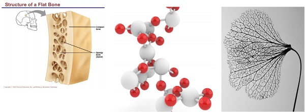
Organic forms have been inspiration for designers since the beginning of times. However due to the geometrical complexity of the natural forms, simple rules of thumb and grids were introduced in architecture to increase its efficiency and feasibility. However, such constraints may hinder design evolution and be detrimental to architectural creativity. Similarly, our engineering principles are based on simplified assumptions due to the low variability of components and the high repetition of the structural systems.
We are now on the brink of the new digital era. Our technologies and understanding of systems allow us to experiment with forms and shapes more effectively than ever. It is therefore clear that there is room for improvement in trying to achieve the free form structures we envisage. The authors strongly hold that new technologies can help us design efficient and optimised structures with the aim to reduce material consumption, fabrication time and costs, and finally explore new architectural expressions. This paper investigates state of the art methods of digital design and digital fabrication with glass and aims to propose ways of seamlessly combining the two to achieve an desirable result.
2. Digital Design
[Bejan A , 2000] considers the design and optimization of engineered systems and presents a relationship to the generation of geometric form in natural systems. He argues that the objective and constraints principles in engineering are the same mechanisms underlying the geometry in natural systems. Evolutionary and randomized statistical algorithms like Galapagos and Monte Carlo were successfully deployed to optimize solutions in many engineering problems.
Current engineering practice is presented with the challenge of having to go through multiple permutations and assess their feasibility in real time. Parametric software has given us the opportunity to efficiently and effectively incorporate the extra step of structural engineering into the design process. With software such as Karamba, we can automatically carry out a preliminary assessment of the structural behaviour of a certain permutation.
However, in the construction industry the flow of information is not smooth. The design tools are usually not centralised and therefore cannot be used by all collaborators and certainly not throughout all stages. Hence, design workflows need to be carefully planned and a central platform to exchange information should be defined. Only then will the process be automated to such an extent that it will positively influence the design process.
The main difference between the way we design today and the way we used to design is that new tools are incorporated into the design process transforming an otherwise static procedure into a dynamic workflow. Twenty years ago, the designer would sketch an idea, CAD it up, carry out the structural analysis, check the design against other requirements such as movements, tolerances etc in a very linear workflow. If validation could not be achieved in one of those steps, the process would have to go back to initial sketching. Nowadays, we are given the chance to design a workflow that can instantly check the design against performance requirements or even optimise the design based on those parameters.
Glass design can easily fit into this trend and the authors cannot see any major reasons why current trends could not be fully deployed in our industry. Many scripts helping with design of geometrically complex glass envelopes have been employed in the past and will continue to be employed e.g. checking glass warping and sub-sequential stress in glass and other components, analysing climatic loads in curved panels were presented by [Marinov, V, Griffith, J, 2015] and near future possibility to use AI by [Griffith, J, 2017].
However, while parametric tools have been continuously introduced in the design process, generative design with glass as the main structural material poses significant challenges. Glass is different from other materials due to its brittle nature. Peak stresses can therefore be detrimental to the behaviour of the structure and support conditions must be carefully modelled on a case by case process. This makes the use of universal scripts more difficult. Finally, glass as a material is normally used in planar elements the structural calculation of which typically requires a FEA. This is normally expected to slow down the design process making the use of generative scripts more challenging.
3. Digital Fabrication
If we were to simplify the architectural manifestos of the 20th, the concept of fluidity has always been a divisive term. There were movements which embraced fluid shapes and other movements which alienated themselves from organic forms. It is well established that new architectural movements derive from a need to contrast the past, and to explore the undiscovered. The movements of Arts & Crafts and Art Deco introduced the concept of seamless architecture.
This architectural expression would require highly skilled workmanship and a significant amount of manual work. This came as a reaction to the industrial revolution and the need for mass production. This was later challenged by modern architecture which in turn was challenged by the post-modernists. There always seemed to be a contrast between the mass produced and the bespoke. But what if something could be bespoke and mass produced at the same time?
Fabrication techniques are divided into three main categories: a) forming, b) cutting, and c) joining. Each of these have opportunities for glass which are briefly explored below.
Forming
Additive manufacturing
3D printing is available from a limited number of sources worldwide. At present, it is costly but has the potential to open the door to unlimited design options. Research resources are dedicated into investigating the molecular behaviour of 3D printed glass and therefore its mechanical properties.
Subtractive manufacturing
3D milling of glass is a relatively new process which is commonly used to give glass some texture. The fact that milled glass may lock in residual stresses makes it challenging to link this process with generative design as an intermediate step of detailed FEA should be introduced.
Shaping
3D shaping glass is the oldest known way of forming glass. Glass can be kiln formed or cast in 3D shapes. However, methods of 3D shaping require the use of a mould. Hence, repetitiveness and manual work are still required and therefore the method is inherently non-digital.
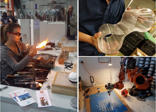
Figure 3b. MIT casted glass example, photo: James Griffith
Figure 3c. AI Built, robotic arm printing PLA
Cutting
Glass can be easily manipulated if heated up. The authors do not see any technical reason why the glass industry cannot embrace cutting technics such as die, punch or shear cutting etc.
Joining
Adhesives
Adhesives are commonly used in structural glass applications and range from stiff and brittle acrylate-based to flexible and ductile silicone-based. This is where the authors see the maximum potential of digital fabrication. Industry is currently exploring ways of 3D printing adhesives which is expected to provide a fertile ground for glass fluid shapes to grow.
Mechanical and Fusion/Welding
At present, the process of fusing glass is completely manual and consumed in artistic applications or in glass blowing laboratories. There is high potential in bringing this method into the digital era as its labour-intensive nature is currently keeping it away from the digital transformation.
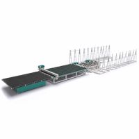
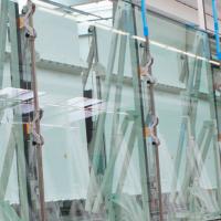
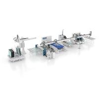
In conclusion, the glass industry has been exploring the digital world and, in some areas, is well advanced: automation of manufacturing processes is relatively well evolved, automated glass production and processing lines do exist, and DGU assembly lines form part of most advanced glass manufacturing facilities. However bespoke project specific glass processing, as well as site installation, are still heavily dependent on manual handling. Not all fabrication processes are available in glass manufacturing and certainly not all of those listed can be considered to be digital.
4. Case Study
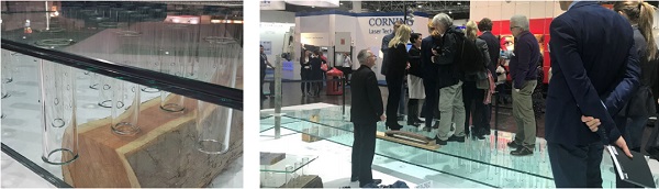
Digital design and fabrication are expected to enhance the efficiency of our work. Arup, in collaboration with Delft University of Technology and SCHOTT, designed and built an all-glass sandwich panel. The panel was exhibited at Glasstec 2018 as a floor, to demonstrate the potential of composite glass structures in structurally demanding applications. The aim was to design a panel that would have high bending stiffness while minimising material consumption.
To achieve this, parametric design methods were employed.
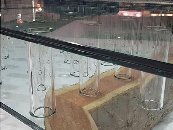
Composite structures typically consist of three main elements: a) two skins, b) a structural core and c) an adhesive layer between. The thickness, the type, the geometry, and the mechanical properties of these constitute design variables. Hence, the design of a composite panel involves several quantifiable parameters that feed into a composite mathematical function. To contain and rationalise the problem, early design decisions were made based on aesthetical constraints. The properties of the skins were defined by means of homogenisation of the section (EI=E’I’); a double glass laminate with 10mm HS glass was used for each skin. Borosilicate glass tubes were used as spacers to provide support to the skins. This spacer was deemed ideal for exhibition purposes as it gives the maximum design potential. Then acrylate adhesive was used to bond the core elements to the skins.
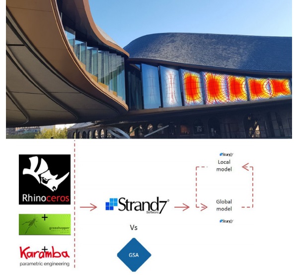
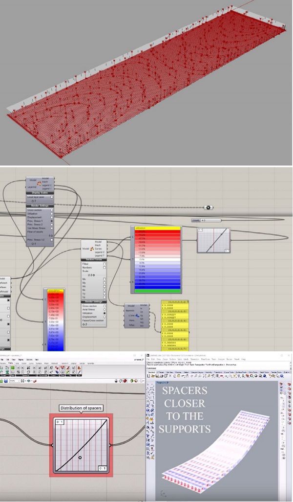
In general, in order to optimise material usage the best balance can be found between the remaining variables: core thickness and distribution of spacers within the core. The final pattern was defined using Karamba/ Grasshopper/Rhino. The pattern was optimised in such a way that shear forces on the beam elements (spacers) are constant across the whole length of the panel. To achieve this, the pattern of the flow of the shear stresses in the plates was printed and spacer elements were placed in the intersection between this pattern and the pattern of the global shear forces. The approach was similar to the distribution of shear studs in steel-concrete composite beams.
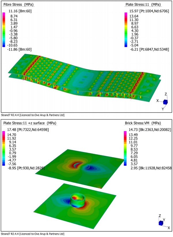
The digital workflow was completed by a detailed FEA using Strand7. The adhesive connection between one glass spacer and the glass skin was modelled with brick elements. The resulting connection stiffness fed back onto the parametric model in the form of nodal rotational stiffnesses to further refine the pattern. In short, the above described process yields an optimised and therefore efficient result which achieves the maximum stiffness to weight ratio. The real benefit of this application is that once those constraints are set, the design script is available to instantly churn out numerous structurally validated results based on changing loads and boundary conditions. The downside is that the resulting pattern comes out of an intricate computational process and therefore is not orthogonal and as such it poses fabrication/ assembly challenges.
For the construction of each panel, 150 spacers were required and those had to be manually placed and glued. This process was time-consuming, labour-intensive and required rationalisation of the pattern leading to an increase in the number of spacers by 30%. This suggests the barrier between digital design and fabrication is sometimes prohibitive when it comes to real innovation and optimisation.
In other industries e.g. automotive, furniture etc. robotic fabrication is fully embraced. One could argue that the difference between those industries and the construction industry is that in the built environment, most endeavours are bespoke and therefore any economies of scale are applicable only within the strict boundaries of a particular project. Contemporary architecture is leaning towards organic and intricate shapes with minimum repetitiveness. This new architectural language suggests that structural glass applications could certainly benefit from a seamless transition between digital design and digital fabrication.
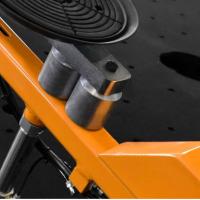
In this case, the positioning of the spacers at the right location within the core could have been achieved with a robotic arm and the appropriate end-effector. Parameters related to the precision of a robot movement e.g. spatial resolution, accuracy, and repeatability are well within the range of tolerances typically provided in the construction industry and are therefore covered by relevant safety factors. Furthermore, a digitally controlled application of adhesives would also be beneficial for this application. However, the precision required for acrylate adhesives cannot be achieved with existing means without post-processing of the joint.
While the built environment is shifting towards solutions that promote sustainability, together digital design and fabrication can guarantee more efficient use of available resources without putting architectural innovation in jeopardy.
5. Conclusion
The trend towards complex engineering systems, especially in geometry, is noticeable. Architecture has moved to digital space where manipulating complex geometrical forms is as easy as it was defining rectilinear orthogonal building structures on the drawing board in the past. When heat-changed to fluid, glass allows us to manipulate its shape relatively effortlessly. This mechanical property is a great advantage and could be used in digital fabrication.
Even though the high level of complexity of structural glass applications does not provide a fertile ground for generative design, digital design is essential in glass design as it significantly assists in accommodating intricate geometries, exploring different support conditions, and generally going through multiple design iterations. Other industries make good use of digital tools. A very good example of effective use of a digital design to fabrication workflow comes from the furniture and industrial design industry. The Breeding Tables designed by [Kraam, Weishaar, 2005] constitute the perfect example of how mass customisation can be achieved using genetic algorithms. What if we could use the same tools and principles to design and fabricate glass structures with the click of a button?
6. Acknowledgement
TU Delft Glass & Transparency group, Prof. Rob Nijsse, Dr. Fred Veer, Faidra Oikonomopoulou, Graham Dodd at Arup for his support and comments & James Griffith for photographs 2a.) and 3b.)
7. References
[1] Bejan, A., 2000, Shape and structure from engineering to nature, Cambridge University Press 344 pages (ISBN 0-521-79049-2)
[2] Marinov, V., Griffith, J 2015, Optimisation of curved insulated glass In GPD 2015, Finland 2015
[3] Griffith, J., 2017 Applied machine learning in structural glass design In GPD 2017, Finland 2017
[4] Kraam, R., Weisshaar, C., 2005, http://www.kramweisshaar.com
[5] Thompson, R., 2007, Manufacturing Processes for Design Professionals
[6] Kolarevic, B., 2003, Architecture in the Digital Age: Design and Manufacturing
[7] Lefteri, C., 2007 Making it: Manufacturing Techniques for Product Design