
The steel without the glass would have little lateral stability, and would not survive a wind storm. The overhead glazing was developed into a 30m long lateral beam using a series of unique but simple point fitting connectors. A glass "knee" structurally connected the two halves of the pier. A number of special technical problems were required to be resolved because of the rigid attachment of steel to glass, including the relative thermal movement of the dissimilar materials. Designed in collaboration with Diller Scofidio & Renfro Architects, the structure is an architectural feature of the Lincoln Center development.
Introduction
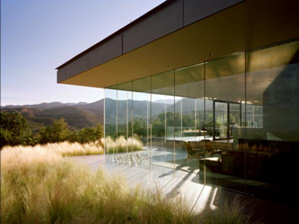
The canopies at the Lincoln Center in New York City are both functional entry ways as well as aesthetic features of the campus. The canopies is a glass and steel composite structure, where the glass is part of the load path for both dead and live loads. They formed the centerpiece of 2010 Fashion Week that was held at the Lincoln Center.
The overhead glazing provided lateral strength for the structure, and the two halves of the pier were held together with a glass knee.
Precedent structures leading up to the development of this canopy were the Brooklyn Academy of Music Canopy and the Klein house. The glass forms the tension element in a derrick crane type structure, and was completed in 2007. The Klein house features glass walls that hold up the roof. Both of these projects included glass supporting steel, provided valuable lessons for the design of the Lincoln Center canopies.
.jpg)
Figure: Finished structure
.jpg)
Figure: Finished structure
.jpg)
Figure: Brooklyn Academy of Music Canopy. Overhead glazing is in tension to hold up the steel frame.
.jpg)
Klein house
Load paths
The canopy beams were cantilevered from the piers by 11.6m with a backspan of14.0m, and laterally braced by the overhead glazing. The pier was split into two halves, with each half working compositely with the other because of the connection through the glass knees.

Figure: Glass knee holds two halves of the pier together

Lateral system
Figure: Plan view of canopy. Glazing forms part of the lateral system.
Aeroelastic Performance
The structure is relatively stiff in the vertical horizontal directions, though it relatively flexible in the torsion mode. Its first natural frequency is 2Hz in the torsion mode. Additionally, its cross section is comparable to that of a suspension bridge, and there was some concern about the vortex shedding causing the bridge to become aerodynamically unstable in the torsion mode, in a similar manner to the famous Tacoma Narrows Bridge collapse in the 1940’s.
The bridge has a large flat surface which can twist. When it twists, it picks up more wind load, and then elastically moves to the opposite twisted position. This combines with some vortex shedding and other asymmetric wind loads to form the potential for aerodynamic instalbility.
.jpg)
Figure : Tacoma Narrows Bridge Collapse
.jpg)
Figure: Cross section
This aeroelastic concern was addressed in a number of ways. Firstly the mass and stiffness of the structure were tuned to ensure the first natural mode of vibration exceeded 2.5Hz.
An aeroelastic wind tunnel was completed by Wacker Ingenieure in Germany. An aeroelastic wind tunnel differs from a regular model in that the stiffess of the actual structure is included in the test model. Normally, rigid models are used. The advantage of the aeroelastic approach is that the feedback between the structure and the wind can be take into account.
.jpg)
Figure: Wind tunnel test
Thermal expansion
The coefficient of thermal expansion of steel is 12 μϵ /oC, whereas the coefficient of thermal expansion of glass is 8 μϵ /oC. Additionally, glass’s transparency combined with steel’s opacity mean that the two materials absorb different amounts of solar radiation, leading to there being a difference in thermal movements between glass and steel. Glass is a brittle material, so no local yielding could be counted on, yet the glass was expected to work compositely with the steel.
A number of options were studied to address this concern. They could be broken down into the following basic approaches:
- Forming the glass into an effectively statically determinate truss system
- Providing a regime of slotted holes to relieve thermal movements
- Providing semi-rigid joints
- Structural silicone joints
Ultimately the semi-rigid joints model was determined to be the most practical. Drilled point fittings were installed between the steel and the glass, and the bearing included a neoprene bush that introduced the required flexibility. This additional flexibility affected the global structural stiffness in other less desirable ways, particularly the natural frequency.

Figure: Detail of semi-rigid joint

Figure: Test apparatus
The exact stiffness of the semi rigid joint was difficult to determine accurately analytically, so tests were performed for this purpose. Accurate force vs displacement diagrams were produced. The neoprene was the source of the flexibility in the system, and neoprene is a close to incompressible material with a Poisson’s ratio near 0.5. As such, its expansion under load was taken into account in the test, particularly as relates to the bond of the neoprene to the substrate.

Figure: Force-displacement curves from test
Redundancy
With glass as an essential part of the load path, yet a brittle and breakable, redundancy was a key design consideration.
All structural glass was laminated with four plies such that the loss of any one would reduce the bending capacity of the glass by no more than 30%.
A SentryGlas interlayer was used throughout the project in order to provide post breakage performance. In the instance of total four ply glass breakage, the SentryGlas has tension strength, and thus some membrane and beam action can be developed with the broken glass. The broken glass can carry some compression, and combined with tension in the interlayer, flexure is possible.
The glass knee held the two halves of the column together, and carried significant dead load. If the glass knee was to fail completely, the steel had enough capacity to survive under at least dead load.
The structure was also engineered for any one total panel loss, whether accidental or during replacement. There were two completely independent glass knees, and either could be lost catastrophically. The overhead steel beams had enough lateral strength to be able to span across a missing panel.
iPhone testing
iPhones incorporate accelerometers into their hardware, and additionally have the ability to query all of the hardware at a component level. An app was downloaded that recorded the acceleration data at a frequency of 1000Hz, and downloaded to a data file.
This acceleration data could be converted into displacement data by integrating the accelerations over time, and compared with the theoretical movements predicted by the models. Good correlation was shown.
.jpg)
Figure: Dewhurst Macfarlane engineer Nick Roach collecting iPhone dynamic test data.
Conclusions and Summary
Glass is an inherently strong material, and with proper detailing can contribute significantly to the total structure’s stability instead of simply being a secondary element. The Lincoln Center Canopies showed that this could be possible.
Acknowledgments
This project, like all others, was the product of collaboration of many partners. The work was completed whilst the author was an engineer with Dewhurst Macfarlane & Partners in New York. The project would not have been possible without the following individuals: Nick Roach (Dewhurst Macfarlane & Partners), Siegfried Gossner (Seele), Bruno Kasnel Henneberg (Seele), Ben Gilmartin (Diller Scofidio & Renfro), Robert Condon (Diller Scofidio & Renfro), Liz Diller (Diller Scofidio & Renfro), Jochen Riederer (Knippers Helbig), and Michael Buselmeier (Wacker Ingeniure).
AUTHOR: Michael Ludvik, PE, M.Ludvik Engineering
The paper has been firstly published in 2011 GPD Conference Proceedings Book, p. 589-592


 demonstrator at Glass Technology Live during Glasstec 2024 (© Cas Maertens).")


