
Authors:
Barou, L.; Oikonomopoulou, F.; Bristogianni, T.; Veer, F.A.; Nijsse, R
Published in
12th International Conference on Structural Analysis of Historical Constructions
Abstract. This paper explores a novel restoration approach for consolidating historic structures using structural glass to substitute for the missing elements, preserving at the same time the structural integrity of the structure. A restoration design is proposed for the hypothetical consolidation of the remaining tower of Schaesberg Castle, in Limburg, The Netherlands. The masonry walls suffer from a significant loss of material and a temporary steel structure currently prevents the tower from collapsing. It is proposed to use stacked float glass to fill the missing parts of the wall. The connection between the old masonry and new glass is the most challenging aspect given the different physical and mechanical properties of the materials, which need to work together in a coherent way. Shear tests of various connecting materials are carried out in order to evaluate the performance of this connection with respect to aspects of compatibility and feasibility.
1 INTRODUCTION
Materiality appears as one of the most controversial aspects in conservation and restoration practice and during the last centuries it has been interpreted in different ways aiming to reinstate the authentic image of our historic structures. On the one hand, our ambition is to intervene as little as possible to these structures in order to preserve their historical value (preservation) and on the other hand we aim to restore them efficiently enough to prolong their life and function in the future (restoration). These ambitions often conflict with each other, stressing the choice of materials and the degree of intervention as important aspects of the conservation approach. In practice, the use of traditional materials bears the risk of conjecture between the original and new elements, while modern materials may appear imposing over the existing ones and impair their authentic image, resulting in irreversible and intrusive interventions. The current conservation and restoration guidelines provide ambiguous recommendations on how to address the issue of materiality, emphasizing aspects of harmonious integration, compatibility and reversibility of any intervention [1,2].
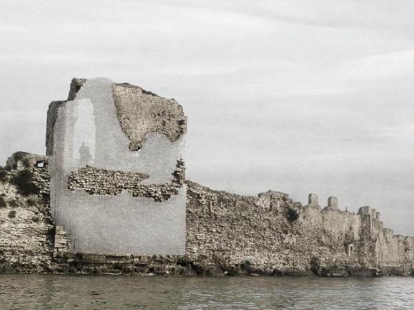
Glass is proposed as a solution in this on-going materiality debate. The aesthetic qualities, durability and mechanical properties of glass are some of the benefits of using it in conservation practices [3]. In particular, a Fill-in-Glass Restoration approach introduces glass elements in order not only to complete the missing form of the damaged structure, but also to reinstate its structural integrity (Figure 1). Both the new and old materials work together in an integral way, raising attention to compatibility1 issues, as the most critical part. The authors address this topic on three interdependent levels; aesthetic, structural and material compatibility and demonstrate that the design of the interface between the different materials is the most challenging and yet unknown aspect.
![Figure 1: Fill-in-Glass Restoration design proposal for the consolidation of Bembo’s bastion in Greece [6]](/sites/default/files/inline-images/Fig1_158.jpg)
Towards this direction, this paper aims to explore the structural compatibility of adhesive connections between glass and historic materials, namely clay brick masonry. To demonstrate the feasibility and limitations of the concept, the hypothetical case study of Schaesberg Castle is used for the development of the design. An experimental program is carried out to evaluate the shear bond between float glass elements in stack configuration and clay bricks testing different types of connecting materials.
1 According to [4,5], compatibility expresses the ability of a conservation treatment to avoid any negative consequences that can damage, have negative effects or hinder future treatments of the historic materials.
2 THE CASE STUDY: SCHAESBERG CASTLE
Schaesberg Castle dates back to the 16th century and was built in two phases (1571 and 1616) as the residence of one of the most prominent families of the Cologne-Lower Rhine area (Limburg) in the Netherlands. The castle was made in Mosan Renaissance style, a regional style characterized by stone-framed windows, decorated architraves and alternating layers of brick and stone. The masonry walls are 1 meter thick and consist primarily of a homogeneous core of field fired clay bricks and Kunrade limestone, supplied by a local quarry, for the architectural details such as corners, window frames and horizontal bands.
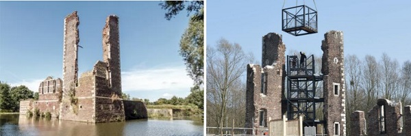
Over the last centuries the castle slowly fell into decline mainly due to neglect and lack of maintenance. Other causes of decay are WWII and vandalism which resulted in extensive loss of historical materials, such as stones and anchor plates. Previous consolidation attempts, archaeological and geotechnical works, fluctuations of the underground water level and ground porosity are assumed to have contributed to settlement of the soil and consequently the foundations. Today, the remaining tower is temporarily supported by a new steel structure built on top of a concrete ballast, in order to stabilize the walls (Figure 2). Steel tie anchors connect the new structure to the masonry walls at different levels to reinstate stability and counteract the wind loads. The steel structure is accessible through a staircase, which makes the tower functional as viewpoint.
Despite its temporary nature, such structure is rather incompatible with the restoration and conservation principles, as well as visually and physically intrusive to the historic materials. In the context of Fill-in-Glass Restoration approach a proposal is made for the permanent consolidation of the remaining tower using structural glass components to reproduce the corner walls of the tower and reinstate their structural integrity. The restoration aims to:
- respect the aesthetic qualities and historic value of the existing structure
- be minimally intrusive to the historic fabric
- ensure compatibility between the old and new materials, minimizing further degradation and allowing for future maintenance
- ensure structural integrity through the design of the connections, which need to act as the weakest link and provide a warning mechanism
3 DESIGN METHODOLOGY
3.1 Materiality
Glass can attain a wide range of aesthetic qualities, which depend on the composition, manufacture technique and configuration. Float, cast and extruded glass elements are the available products used today in various architectural and structural applications. All glass types could potentially be used in restoration and consolidation applications, depending on the materiality of the historic elements, desired degree of transparency and desired degree of resemblance to the original structure [3]. The structural glass assembly needs also to be in harmony with the existing structure and thus satisfy the aesthetic compatibility requirements.
In this context, for the case of Schaesberg Castle a stacked float glass system is explored (Figure 3). The existing construction system of building is based on masonry composed of field fired clay bricks, Kunrade limestone and lime based mortar. The tectonics of the historic construction is defined by this layering of units bonded together with the mortar. Hence, a stacked configuration of float glass elements is chosen to resemble this layering in an abstract way, respecting the principles of the original construction method. The appearance of the glass assembly is more translucent than transparent and depends highly on the glass recipe2 , bonding properties3 and thickness (Figure 3). In general, the advantages of horizontally stacked float glass configurations are the following:
- high load bearing capacity: the vertical loads (self-weight) are introduced in the middle of the panel and not at the edges, which are weaker [8].
- wide range of architectural possibilities: the panels can be cut in any shape with a waterjet cutting machine
- potential for the connection design of glass to the ruined parts of the structure: easily adjustable to rough, uneven surfaces
- the float glass production line is widely available, so the costs are lower than for glass produced with other production methods
![Figure 3: Proposal for the restoration of Schaesberg Castle with horizontally stacked glass elements (left) and the perception of glass and masonry as an artistic installation on a historic flourmill designed by the artist C.Varotsos (right) [9].](/sites/default/files/inline-images/Fig3_148.jpg)
2 The addition of metallic oxides in the glass recipe is responsible for the tint that each glass has. For instance, the most common soda-lime silica glass recipe has a green tint because of the presence of iron oxide [7].
3 A tint can also be achieved by laminating the glass panels using a colored interlayer (PVB, EVA).
3.2 Stacked float glass assembly
Similar to a common masonry wall, a stacked float glass assembly consists of units and bonding material. Float glass elements with a nominal thickness of 15 mm are horizontally stacked forming elements of 4 layers. Each of these elements represents one layer of the brick masonry and has a minimum weight of 10 kg in order to be easily handled during construction. Along the vertical direction they overlap with each other, similar to a masonry arrangement. Along the horizontal direction they are connected in a tongue and groove interlocking system. The laminated glass elements are bonded together with a transparent double-sized adhesive tape, which works as stabilization mechanism for the entire assembly. The glass assembly consists of annealed glass despite its lower strength4 . This is the preferred type to use in such a configuration, as it meets the requirements on flatness compared to thermally tempered glass (heat-strengthened or tempered), in which variations in flatness may result in local stress concentrations and failure of the glass.
3.3 Interface design
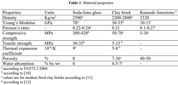
The role of the interface is to connect the old and new structure in a compatible and least intrusive way. Challenges arise when choosing an effective connecting method for materials with very different physical and mechanical properties (Table 1). Despite the density of the historic materials and glass, which is comparable, the different mechanical and physical properties highlight the importance of a proper interface design in order to achieve not only aesthetic but also mechanical collaboration between the old and new structure. Aspects of stiffness, strength, stress distribution and hygrothermal dilatation appear critical for the connection.
With the aim of intervening as little as possible to the existing structure, adhesive connections are designed and developed for this case study, in order to avoid any loss of the historic material (e.g. by drilling holes). Such connections comply also with the existing construction system, which uses mortar to bond the masonry bricks together. More importantly, adhesive connections can achieve a homogeneous load transfer between the old and new structure and accommodate tolerances due to thermal and hygric expansion. Mechanical connections, on the other hand, result in local stress concentrations, which are unfavorable for brittle materials (both masonry and glass) [13]. The requirements for this interface are to:
- accommodate thermal/hygric tolerances
- transfer loads between the old and new
- allow for retreatability in the future
- work as the weakest link between the old and new in order to preserve the historic fabric
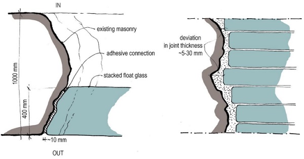
The geometry of the interface is highly influenced by this of the historic structure and glass assembly. 3D-scanning technologies in combination with post-processing treatment of glass plates (prior to lamination) with a water-jet cutting machine can result in a glass assembly with the exact imprint of the ruinous surface. Layer by layer, glass follows the geometry of the existing wall (Figure 4). Due to construction and manufacture tolerances a joint thickness that varies between 5 and 30 mm appears realistic and defines the characteristics of the connecting materials. The two main categories of connecting materials that are taken into consideration are mortars, which are already used in masonry structures, and glues, which are widely used in glass applications. The requirements for each of these alternatives are as follows:
Mortars
- Paste consistency (suitable for vertical joints)
- Low shrinkage
- Low pH to avoid alkali-silica reaction to glass
Adhesives (glues):
- Flexible, semi-rigid to allow for large thicknesses
- Medium-high viscosity
- Long setting time
- Weather resistant (UV, moisture, water, salt)
4 6 MPa for permanent loads and 20 MPa for short-term loads (values including safety factors)
4 EXPERIMENTAL PROGRAM
4.1 Test specimens
Shear tests are performed in order to evaluate the bonding strength of the aforementioned connection alternatives and demonstrate the potential of this system. In total five different connecting materials are tested: two cement-based materials and three types of glues. The aim of this first experimental program is to observe the:
- failure mode of the joint; specifically whether it results in damage to the brick, which represents the historic material
- effect of the edge geometry of the glass assembly (straight compared to saw-tooth pattern)
- effect of different orientation of the stacked glass assembly (horizontal or vertical stacking)
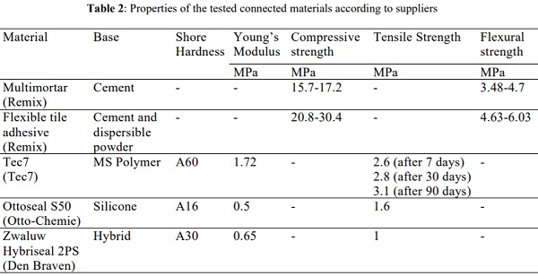
Table 2 shows an overview of the main properties of the connecting materials. Remix Multimortar is a dry multi-purposed cement-based mortar (Class M15), suitable for hollow glass masonries. Remix Flexible Tile Adhesive is an all-round cement-based tile adhesive with polymer additives5 , suitable for bonding ceramic and stone materials for indoor and outdoor use. Both of these materials have a consistency suitable for vertical joints. Three different types of glues are chosen, depending on their properties and base technology. Tec 7 is an MS Polymer-based, strong and permanently elastic adhesive, suitable for glass. Ottoseal S50 is a silicone-based sealant and Zwaluw Hybriseal 2PS is a high-quality professional sealant based on hybrid technology and suitable for bonding glass joints.
For the preparation of the specimens glass plates of 10 mm thickness are cut in shape and manually ground around the edges to minimize the presence of sharp areas that could initiate cracks. All glass edges in contact to the connecting materials are machine ground and polished in flat shape. The glass plates are bonded together using a double-sided adhesive tape in order to prevent any movement and be easily handled during the assembly of the joint6. The joint thickness is 10 mm for set-up 1 and 3 and 10-30 mm for set-up 2, while the contact area is 4.275 mm2 on average. A fast drying, solvent-free styroacrylate primer is applied on the glass surface to increase the adherence of Remix multimortar to the smooth, non-porous surface of glass. The rest of the materials are applied in direct contact to both glass and brick substrates. All specimens are prepared 2 weeks prior the testing.
5 35% cement; 59.9% fine sand; 3.5% dispersible polymer powder; 2% stabilizer for water retention.
6 This bonding system is developed only for the tests and does not correspond to the actual construction method of the laminated glass elements.
4.2 Test set-up
Three different set-ups are used in order to evaluate the shear bond between stacked glass assemblies and brick masonry, as shown in Figure 5. Set-up 1 introduces shear forces perpendicular to the stacking plane, set-up 2 introduces shear forces perpendicular to the stacking plane with the glass plates arranged in a saw-tooth pattern and set-up 3 introduces shear forces parallel to the stacking plane. Set-up 2 aims to create a more realistic representation of the connection compared to set-up 1, with a fluctuation of the thickness joint that is possible to occur due to the rough, uneven surface of the ruin.
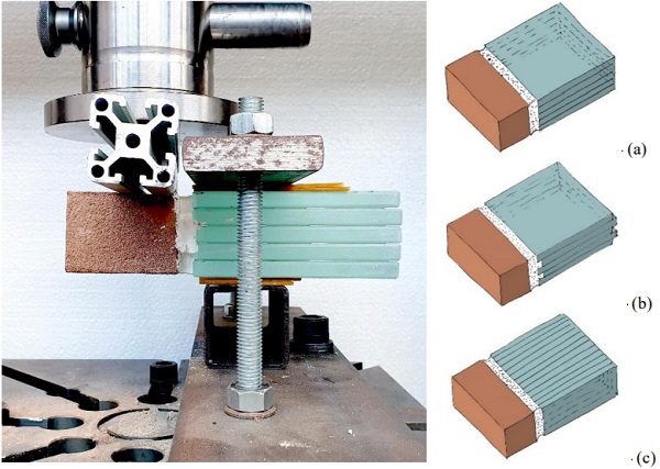
The shear tests are performed in a Zwick Z100 machine. A specially manufactured steel frame is used to clamp the glass assembly to the base and restrain any movements. Soft PU layers, 3 mm thick, are placed in between glass and steel to avoid the hard contact between the materials and ensure an even load distribution. The vertical load is introduced by the displacement of the crosshead against an aluminum tube and then on the brick in two different speeds: 1mm/min, for the first three materials, and 5mm/min for the following two.
4.3 Discussion
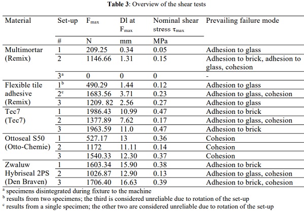
All tested connecting materials show consistent results, which are presented in Table 3 and discussed below according to the aforementioned aims.
4.3.1 Failure mode of the connecting materials
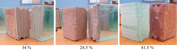
All tested materials show favorable failure modes, namely adhesion to glass, adhesion to brick and cohesion, often in combination. Therefore, the connection works as the weakest link and no damage occurs to either the brick or the glass. An overview of the characteristic failure modes and their occurrence is shown in Figure 6. In general and as expected, the mortar and tile adhesive fail in a brittle way, whereas all adhesives (glues) exhibit significant deformation capacity and the ductile behavior of the joint. For the mortar and tile adhesive, failure mostly occurs by delamination of the glass, which indicates the weak adherence bond to the non-porous glass surface. Most of the adhesives (glues) show the opposite result; failure occurs either by cohesion or by delamination of the brick.
4.3.2 Influence of glass assembly geometry
The edge geometry of the laminated glass plays a crucial role to the shear bond of the joint. For the first two cases of mortar and tile adhesive, specimens of set-up 2 (saw-tooth geometry) show increased load and maximum displacement compared to these of set-up 1 (straight geometry). The high stiffness of the materials in combination with the interlocking pattern contribute positively to the shear capacity of the joint. In the case of the adhesives (glues) the saw-tooth pattern of the glass had the opposite effect, showing decreased values in terms of force and displacement. This result can be explained by considering the influence of the thickness joint in the shear performance of the adhesives. In this context, the recessed areas in the saw-tooth pattern are, in fact, weak areas that reduce the shear capacity of the joint.
4.3.3 Influence of stacked glass orientation
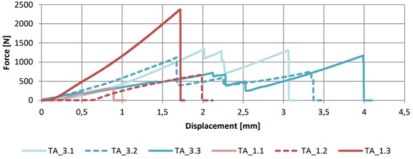
The orientation of the stacked glass elements (set-up 1 compared to set-up 3) plays an important role for the tile adhesive joints. In set-up 3 both the average maximum vertical force and displacement are significantly increased, whereas the joint demonstrates some ductility. This is evident in the force-displacement diagram as shown in Figure 7. Introducing the shear forces parallel to the stacking plane results in higher deformation capacity of the joint. Set-up 3 shows a consistent increase of the joint stiffness after the first crack occurs, avoiding brittle failure compared to set-up 1.
5 CONCLUSIONS
A novel Fill-in-Glass Restoration proposal using structural glass is presented in this paper as a possible answer to the current materiality debate. In the context of exploring the compatibility and feasibility of this concept the case study of Schaesberg Castle is considered. An assembly composed out of horizontally stacked float glass elements completes the missing parts of the historic masonry walls and reinstates its structural integrity. The design of the connection between glass and clay brick masonry is based on materials with adhesive properties. Two cement-based materials and three types of glues are tested in shear order to evaluate the performance of this connection. Although the specimens tested are not sufficient for statistical evaluation and cannot be considered conclusive for establishing mechanical properties, they serve as a first indication of the performance of such system and can be used as basis for future work. Based on the results we can conclude the following:
- All connecting materials exhibit acceptable failure modes that do not result in damaging the historic substructure.
- Specimens bonded with Tec7 demonstrate the highest shear bond between glass and clay brick, as the most rigid glue. Both mortar and tile adhesive show consistently lower shear strength compared to all types of glues.
- The orientation of the stacked glass elements can influence the shear capacity and ductility of joints with brittle connecting materials, showing potential for cases where shear loading parallel to the stacking plane is dominant (e.g. wind load acting on a horizontally stacked glass assembly).
- The saw-tooth pattern as edge geometry of the glass component is favorable to mortars and tile adhesives and has negative effect on glues.
- The joint thickness fluctuations that occur in the interface due to the geometry of the stacked glass assembly can be better tackled using connecting materials with high stiffness (mortars, tile adhesives) rather than flexible glues.
- Polymer additives are crucial to the shear performance of mortar joints as they increase not only their strength, but also their adherence to the glass surface.
Based on these findings, the most promising direction to continue this study is by researching adhesive connections based on mortar-like materials. Although glued connections demonstrate higher shear capacity and ductile failure compared to ones made by cement-based materials, maintenance and future treatment are challenging issues to take into consideration in restoration applications. After degradation glues are replaced rather than repaired and their life expectancy is debatable7 . On the contrary, mortars can be easily maintained (e.g. by grouting).
The challenge, in this case, is the poor adhesion of mortar to the glass surface. Future work will focus on the adhesive bond between glass and different types of modified mortars to establish their mechanical properties. The glass edge treatment is also crucial for the bonding quality. For this paper, tests of glass elements with flat polished edges were considered, however, edge treatments with increased surface area (e.g. pencil, beveled or sandblasted instead of polished) in combination with a saw-tooth geometry could increase the shear capacity of the joint.
7 Approximately 20-30 years for sealants according to [14].
Acknowledgements. This research is carried out in collaboration with ABT bv. The shear tests were carried out at the Faculty of Mechanical, Maritime and Materials Engineering of TU Delft.
REFERENCES
[1] ICOMOS. The Venice Charter: International Charter for the Conservation and Restoration of Monuments and Sites, art. 4, art. 12, art. 13 (1964)
[2] ICOMOS. Principles for the Analysis, Conservation and Structural Restoration of Architectural Heritage, art. 3.7, art. 3.9, art. 3.10 (2003)
[3] Barou, L., Oikonomopoulou, F., Bristogianni, T., Veer, F. and Nijsse, R. Structural glass: A new remedial tool for the consolidation of historic structures. HERON 63 (1-2) (2018), pp. 159-197.
[4] Teutonico, J. M., Charola, A. E., De Witte, E., Grasegger, G., Koestler, R. J., Laurenzi Tabasso, M., Sasse, H. R., and Snethlage, R., Group Report How Can We Ensure the Responsible and Effective Use of Treatments (Cleaning, Consolidation, Protection)?, Dahlem Workshop on Saving Our Architectural Heritage: Conservation of Historic Stone Structures, Baer, N. S. and Snethlage, R. (Eds), Chichester, John Wiley & Sons, (1997), pp. 293-313.
[5] Van Balen, K., Papayianni, I., Van Hees, R., Binda, L. and Waldum, A. RILEM TC 167- COM: Characterisation of old mortars with respect to their repair, Introduction to the requirements for and functions and properties of repair mortars, Materials & Structures. (2005), pp 781-786.
[6] Barou, L.: Transparent Restoration. MSc Thesis. Faculty of Architecture and the Built Environment, Technical University of Delft (2016).
[7] Corning Museum of Glass. What is glass? (2011) https://www.cmog.org/article/what-isglass. Accessed on 26 January 2020.
[8] Van Heugten, R.: Load-bearing Glass Columns: The Stacked Column. MSc Thesis. Eindhoven: Eindhoven University of Technology (2013).
[9] Varotsos, C. Geraki-Horizon (2007). http://www.lakonistas.gr/ena-ergo-toy-varotsou-stinlakonia-by-lakonistas/. Accessed on 26 January 2020.
[10] Granta Design Limited: CES EduPack 2015. In. Granta Design Limited, Cambridge, (2015)
[11] Theodossopoulos, D. Structural Design in Building Conservation. London: Routledge, (2012).
[12] Dubelaar, C. W., Kisters, P. J. M., & Stroucken, J. W. A natural-stone city walk through Maastricht, the Netherlands. Netherlands Journal of Geosciences - Geologie en Mijnbouw (2011), 90(2-3), 197–208. Cambridge University Press.
[13] Oikonomopoulou, F, Bristogianni, T, Karron, K, Groot, C, Veer, F & Nijsse, R , Restoring and structurally reinforcing historic monuments by glass. in A Zingoni (ed.), Proceedings of the 6th International Conference on Structural Engineering, Mechanics and Computation: Cape Town, South Africa. 6th International Conference on Structural Engineering, Mechanics and Computation, (2016), Cape Town, South Africa, 5/09/16.
[14] Mayer, P. Whole life costing: sealants. (2005) http://www.greenspec.co.uk/buildingdesign/sealants-costs/. Accessed on 30 January 2020


 demonstrator at Glass Technology Live during Glasstec 2024 (© Cas Maertens).")


