Challenging Glass 6
Conference on Architectural and Structural Applications of Glass
Louter, Bos, Belis, Veer, Nijsse (Eds.), Delft University of Technology, May 2018.
Copyright © with the authors. All rights reserved.
ISBN 978-94-6366-044-0, https://doi.org/10.7480/cgc.6.2162
Authors:
Vlad Alexandru Silvestru, Oliver Englhardt, Jens Schneider

A trend towards adhesive connections instead of mechanical ones can be observed for transparent facades in recent years. Furthermore, research efforts are made to increase the efficiency regarding material use by designing systems with composite structural behavior. In this article, experimental and numerical results obtained for linear structural silicone joints between glass and stainless steel substrates, investigated separately under tensile and under shear loading, are discussed. The two selected adhesives, Dow Corning® 993 and Sikasil® SG-550, are approved for structural sealant glazing systems and are planned to be used within a novel concept for façade elements with composite structural behavior, consisting of a glass pane and a filigree metal framing.
For an adhesive joint with prismatic geometry, the influence of different lengths, widths and thicknesses of the joint on its mechanical performance is assessed experimentally under tensile loading, while under shear loading only different thicknesses are investigated. Both under tensile and under shear loading, a dependency of the failure engineering stresses on the joint thickness is noticed. In a second step, the suitability of selected hyperelastic models is assessed for predicting the load versus displacement behavior of the investigated linear adhesive joints. The parameters required for these models are determined based on uniaxial tensile tests on dumbbell specimens.
1.Introduction
In recent years, transparency is a popular characteristic of façade designs, especially for public and office buildings. At the same time, the efficiency demands for facades are constantly increasing. Beside the energy efficiency, which can be improved for example by using functional glazing types or adaptive shading elements, the performance of facades is also influenced by the solutions adopted for connections and the optimized material use. In terms of connections, adhesive joints are more and more preferred instead of mechanical fixings for several reasons. Boreholes in the glass panes are not required for adhesive connections and, as a consequence, high local stress concentrations as well as thermal and acoustic bridges can be avoided.
Furthermore, adhesive connections, generally, lead to a more aesthetically appealing overall aspect of transparent facades. For linear adhesive joints, the most common applications are structural sealant glazing systems (SSGS), which are regulated in ETAG-002 (EOTA 2001) and in ASTM C 1401-02 (ASTM 2002). For these systems, glass panes are circumferentially bonded to frame profiles made of aluminum, stainless steel or timber by elastomeric silicone adhesives with relatively low strength and high flexibility.
The advantages of this type of adhesives are on the one hand that they are well investigated compared to other adhesive types and on the other hand that their properties do not significantly degrade over time. Because of the knowledge existing on silicone adhesives, generally at least one such material is included as reference in research projects focusing on the selection of adhesives for new applications (Belis et al. 2011; Overend et al. 2011, Nicklisch et al. 2014).
In terms of efficient material use, efforts are made to design systems with composite structural behavior which take advantage of the properties of the involved materials. For façades, studies to activate the glazing as a bracing element by circumferential adhesive bonding have been carried out by Wellershoff (2006) and by Huveners (2009). In these two projects, four bars made of steel were connected with hinges at their ends in order to form a squared frame. The steel bars, to which a glass pane was circumferentially adhesively bonded, had a large out-of-plane stiffness.
However, silicone adhesives were considered unsuitable for these applications because of their low strength and stiffness. Acrylic adhesives and polyurethanes were preferred within these two research projects. The use of glass panes as bracing elements for single-story buildings was investigated by Mocibob (2008). For supporting the glass panes spanning from ground to ceiling, a concept which combines silicone adhesive bonding and grouting was used.
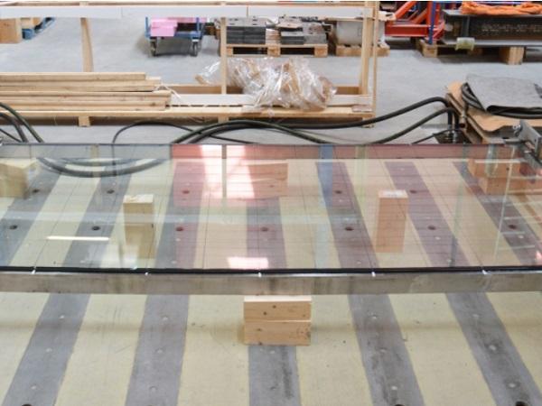
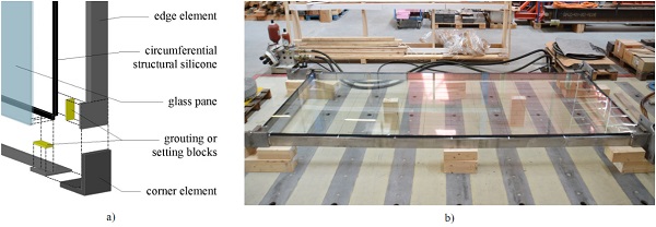
Aiming at developing an innovative façade system which uses the glazing as bracing components and spans over more than one story, the glass-metal elements as illustrated in Fig. 1 are introduced in this contribution. These elements were developed based on the concept introduced by Mocibob (2008) as well as considering the fact that silicone adhesives are the only ones approved by authorities for the use in façade applications.
As shown in the conceptual sketch from Fig. 1a), the elements consist of a relatively filigree metal framing and a glass pane which are bondedtogether circumferentially with a structural silicone joint. Because the shear stiffness of the silicone adhesive is too low for activating alone the glass pane as a shear panel, grouting or setting blocks are additionally positioned near the corners of the glass pane. Investigations on the transfer of compressive loads by setting blocks or grouting at the glass edge were previously conducted by Wellershoff (2006) and by Englhardt (2007).
The silicone adhesive is planned to transfer the out-of-plane loads between framing and glass pane, while in-plane loads are transferred by the grouting or by the setting blocks. Beside the combined load transfer mechanism, the introduced elements differ from similar systems investigated previously through the fact that the filigree framing (see Fig.1b) does not act as a rigid out-of-plane support for the glass pane. Elements with monolithic glass panes and with laminated glass panes were investigated experimentally and by finite element simulations. Moreover, the simplified developed concept can be applied for insulating glazing too. In this contribution, results from investigations at material and connection level for two structural silicone adhesives considered for these innovative elements are presented and discussed.
2.Materials and methods
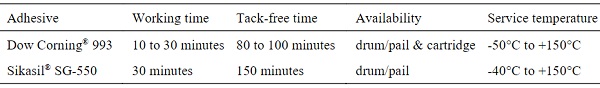
The two structural silicones included in the investigations which are discussed in this paper show in general similar characteristics. Both materials are two-component-silicones which cure by polycondensation and have a density of 1.30 kg/l after mixing. For Dow Corning® 993, the base component and the catalyst should be mixed in a ratio of 7.8:1 by volume, while for Sikasil® SG-550 the mixing ratio by volume should be 10:1. Further selected specifications required for manufacturing as well as the service temperatures according to the product data sheets (Dow Corning 2014 and Sika 2016) are provided for the two adhesives in Table 1. Certain strength and stiffness values are given as well in the product data sheets, but, since these values are determined according to different standards for the two silicones, they are not included here.
Table 1: Selected specifications for the investigated structural silicones according to Dow Corning (2014) and to Sika (2016).
Dow Corning® 993 is probably the adhesive for structural glass applications for which the most research results are available. Its performance is well investigated under different types of loads and under different environmental conditions (Dias et al. 2014; Staudt et al. 2014; Hagl 2016). Moreover, material models, mainly hyperelastic ones, are proposed in literature for predicting its structural performance in finite element simulations. Sikasil® SG-550 is a silicone adhesive with slightly higher strength according to (Sika 2016) which was developed from the more often used silicone adhesive Sikasil® SG-500. The material properties of the latter product were investigated in (Van Lancker et al. 2016). Moreover, this adhesive was also included in studies on suitable adhesives for glass-metal joints (Belis et al. 2011) and for glass-timber joints (Nicklisch et al. 2014). For Sikasil® SG-550 however, only few research results are available (Nardini and Doebbel 2015).
For the two silicone adhesives mentioned in Table 1, results from uniaxial tensile tests on dumbbell specimens as well as from tensile and shear tests on linear glass-stainless steel joints are discussed in this contribution. All these tests were performed at ambient conditions of ~23°C and ~50% relative humidity. The test specimens and setups are described in the next subsections. For the connection tests, the glass substrates were made of monolithic thermally toughened glass panes with a thickness of 10 mm for all specimens. The stainless steel substrates consisted of the material no. 1.4404 and all the bonded surfaces showed grinded finishes with abrasive paper P300. Before the application of the silicones, all bonded surfaces were treated as recommended by the adhesive producers: the glass surfaces were wiped over with cleaners and the stainless steel surfaces with both cleaners and primers.
2.1.Uniaxial tensile tests on dumbbell specimens
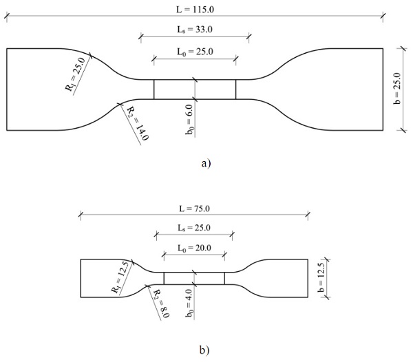
For the uniaxial tensile tests on dumbbell specimens different specimen types were used for the two silicones: (i)specimens of type C according to ASTM D412 (ASTM 2013) for Dow Corning® 993 and (ii)specimens of type 2 according to ISO 37 (ISO 2011) for Sikasil® SG-550. The geometry and the nominal dimensions of the two specimen types are shown in Fig. 2. Both specimen types have a nominal thickness value of 2.0 mm. All uniaxial tensile tests were performed displacement-controlled with a speed of 5 mm/min. For the Dow Corning® 993 specimens a Shimadzu testing machine with a 100 kN load cell was used. The deformations were measured with a video-extensometer. The Sikasil® SG-550 specimens were tested on a Zwick/Roell testing machine for loads up to 2.5 kN. The deformations were measured with a touching extensometer with soft calipers.
2.2.Tensile tests on linear glass-stainless steel joints
The geometry of the specimens used for these tests is illustrated in Fig. 3a). A stainless steel sheet is bonded perpendicularly to a monolithic glass pane by a prismatic silicone joint. Starting from a joint with the dimensions length (l) x width (w) x thickness (t) of 100 mm x 20 mm x 12 mm, which is considered as a reference, all three dimensions are varied. Two additional lengths of 50 mm and 200 mm, two additional widths of 10 mm and 30 mm and two additional thicknesses of 6 mm and 18 mm are investigated. The stainless steel sheets have different lengths and widths depending on the size of the adhesive joints.
Only one dimension of the joint is changed at a time. Six specimens were produced and tested for the reference series and three specimens for each other joint size. Therefore a total of 24 specimens are included in these investigations for each of the two silicones. After manufacturing, the test specimens are stored in a climatic chamber at 23°C and 50% relative humidity for 28 days in accordance to ETAG-002 (EOTA 2001).
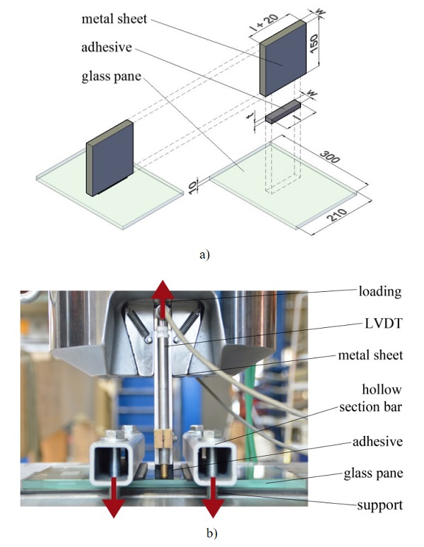
An electromechanical testing machine BETA1000 equipped with a 100 kN load cell is used for these tests. The tensile load is applied displacement-controlled on the stainless steel sheets with clamping jaws as illustrated in Fig. 3b). Adisplacement rate of 5 mm/min is used. The glass panes are restrained to the machine table with two square hollow section bars. Elastomeric layers are positioned between the glass panes and the metal components to avoid glass failure due to local stress peaks. In order to measure only the displacements occurring in the silicone adhesive as well as an eventual rotation of the joint, one inductive displacement transducer (LVDT - linear variable differential transformer) is positioned on each front side of the stainless steel sheets.
2.3.Double-lap shear tests on linear glass-stainless steel joints
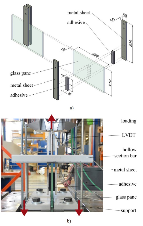
In the case of the specimens used for the double-lap shear tests, one stainless steel sheet was bonded on each side of a glass pane. The geometry of the specimens along with the dimensions of the glass pane and the stainless steel sheets are illustrated in Fig. 4a). Starting from adhesive joints with the same size as in the case of the tensile tests (100 mm x 20 mm x 12 mm), only the thickness was varied under shear loading. Two additional thicknesses of 6 mm and 18 mm were investigated. Six specimens were produced for the reference series and three specimens for each other thickness. The specimens were stored before testing under the same conditions as in the case of the tensile tests.
The double-lap shear tests were performed on the same machine as the tensile tests. The test setup is shown in Fig. 4b). Two square hollow section bars were used to hold down the glass panes in a standing position. Furthermore, two steel sheets were fixed on the machine table at the bottom of the glass panes to restrain them laterally. The load was applied displacement-controlled with clamping jaws on a metal adapter part which was connected between the two stainless steel sheets. A displacement rate of 5 mm/min was used to pull the stainless steel sheets upwards, parallel to the glass pane. Since elastomeric layers were used again to avoid direct contact between the metal components and the glass panes, the relative movement between the stainless steel sheets and the glass panes was measured with one inductive displacement transducer in each of the two laps.
3.Experimental and numerical results
The results from the uniaxial tensile tests and from the two different test types on silicone joints are discussed in the following subsections separately. First, the mechanical behavior of the two silicones under uniaxial tension is characterized and coefficients for selected hyperelastic material laws are determined. Afterwards, the mechanical performance of the linear silicone joints under tensile and under shear loading is discussed. Furthermore, results from finite element simulations are compared to the experimental results for the linear silicone joints. The two adhesives are modelled with linear-elastic material laws in a first step and with one selected hyperelastic material law based on the previously determined parameters in a second step.
3.1.Material properties and models based on uniaxial tensile tests
For the uniaxial tensile tests, the results are evaluated in the form of stressvs. strain curves based on engineering values. This means that the stresses are determined by dividing the measured forces, F, through the initial cross section area, A0 = b0 x t0, where b0 and t0 are the initial measured width and thickness, respectively, along the measurement length, L0 (see Fig. 2). The strains are determined by dividing the extension of the measurement length in load direction, ΔL, through the initial measurement length, L0. The results from the experimental tests are plotted as light grey continuous curves in Fig. 5a) for Dow Corning® 993 and in Fig. 5b) for Sikasil® SG-550.
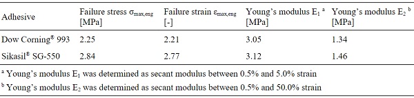
The curves obtained for different specimens of the same adhesive show a good agreement to each other. However, it can be noticed that the results for Dow Corning® 993 show a stronger noise, since the used load cell for up to 100 kN is not well for the small forces recorded during these tests. Mean values for the failure stresses and the corresponding strains are provided in Table 2 for the two silicones. Furthermore, two Young’s modulus values determined between 0.5% and 5.0% strain and between 0.5% and 50.0% strain are given in Table 2. Higher values are reached for the silicone Sikasil® SG-550 in the case of both failure stress and stiffness.
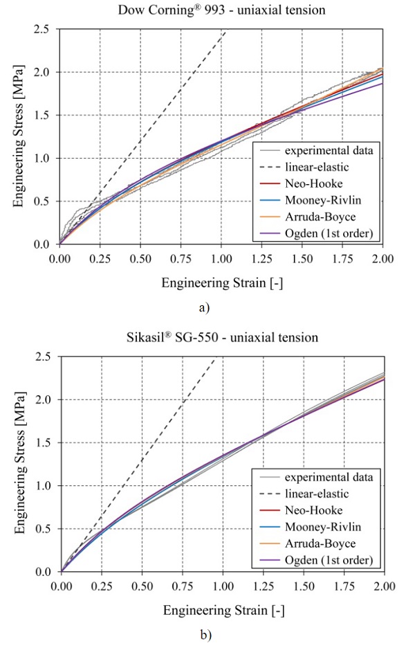
Table 2: Mean values for mechanical properties obtained from the uniaxial tensile tests for the two silicone adhesives.
Additionally to the experimentally determined data, results from finite element simulations are included in the diagrams from Fig. 5. For both silicones a linear-elastic model is first analyzed (results are shown as dark grey dashed curves). For the Young’s moduli, a value of 2.4 MPa is used in the case of Dow Corning® 993 based on (Mocibob 2008), while for Sikasil® SG-550 a value of 2.6 MPa is assumed based on recommendations from the producer. These values lie between the two Young’s modulus values determined in Table 2 for each of the two adhesives.
In the case of both silicones, it can be noticed that, compared to the experimental results, the curves obtained with these Young’s moduli show a slightly lower stiffness for low strains and lead to a significantly increasing overestimation of the stresses for strains larger than ~0.20. To better reproduce the stress-strain relationships of the two silicones, four hyperelastic models based on strain energy potentials are selected and analyzed: Neo-Hooke, Mooney-Rivlin, Arruda-Boyce and Ogden of 1st order (see (Abaqus 2013) for a description of these material laws). Since silicones are considered to be nearly incompressible, only the deviatoric part of the strain energy formulations, which describes an isochoric deformation, is considered, while the volumetric part, which describes the change in volume of the body, is neglected.
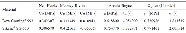
Following the objective of keeping the material laws rather simple, only hyperelastic models with a maximum of two parameters were selected. The parameters for the selected models were determined with the curve fitting tool provided in the engineering software package Abaqus and are given in Table 3 for the two silicones.Compared to the results obtained with the linear-elastic material laws, a significantly better agreement with the curves from the uniaxial tensile tests is reached with all hyperelastic laws. However, all the obtained curves underestimate the experimentally determined stresses for low strains of up to ~0.25, which is the more significant strain range for applications in the façade area.
Table 3: Parameters determined for different hyperelastic material models for the two investigated silicone adhesives.
3.2.Linear glass-stainless steel joints under tensile loading
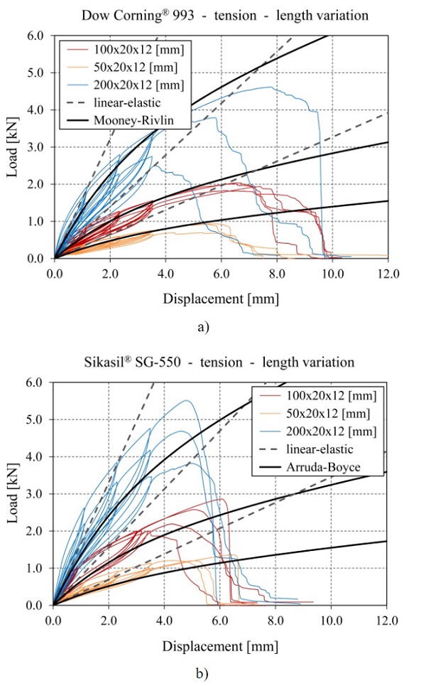
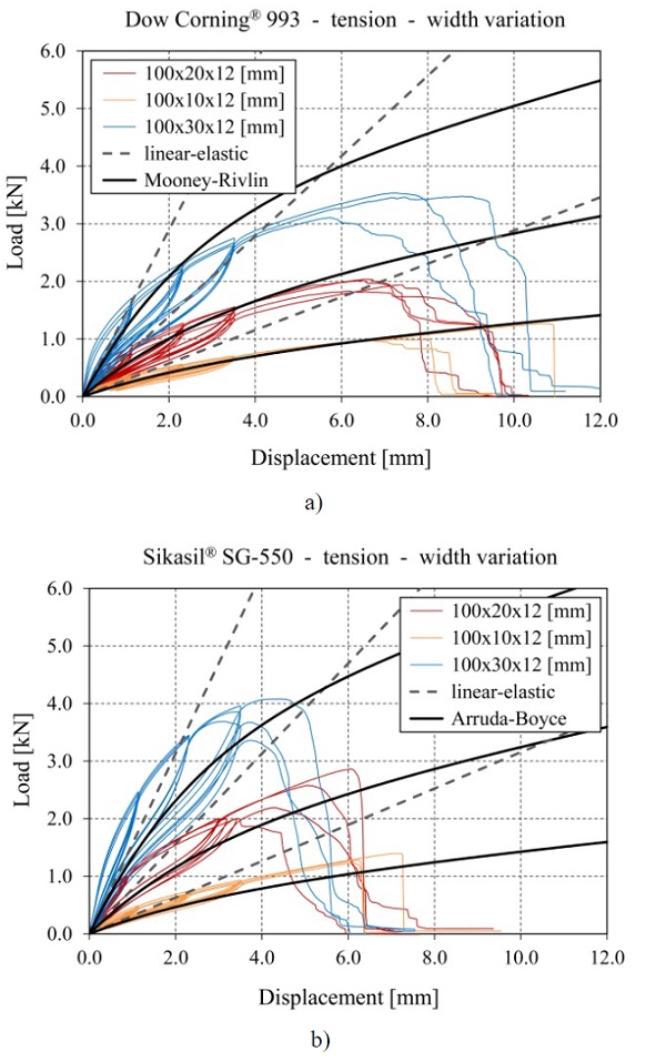
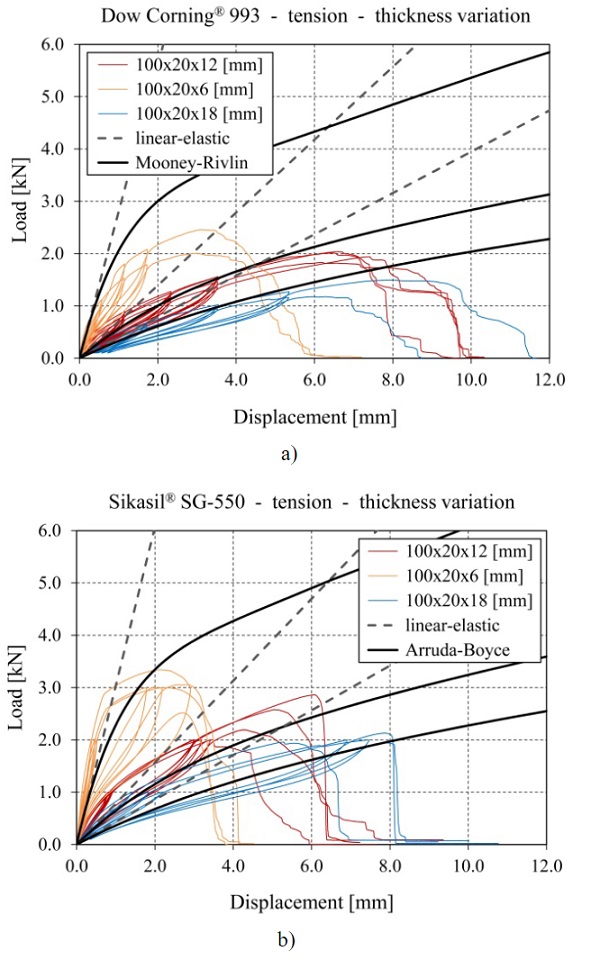
The results from the tensile tests on linear silicone joints are plotted in the diagrams from Fig. 6-8 in the form of load vs. displacement curves as follows: Fig. 6 shows the results from series with different lengths, Fig. 7 shows the results from series with different widths and Fig. 8 shows results from series with different thicknesses. The diagrams on the left include the curves obtained for the specimens with Dow Corning® 993, while the results obtained for the specimens with Sikasil® SG-550 are depicted in the diagrams on the right.
For the reference series, the experimentally obtained curves are plotted only for four specimens, since two specimens from each reference series were considered pilot tests either from a manufacturing point of view or from a testing point of view and were excluded from the evaluation. For a small number of the other series only two curves are plotted instead of three (e.g. 100x20x6 [mm] for Dow Corning® 993), since either the test specimen was damaged before running the test or the measurement instrumentation failed to record data.
At the beginning of each test three load cycles were run until strains of 10%, 20% and 30%, respectively, to capture the influence of the Mullins effect. These results are not further evaluated in this contribution. The data for specimens with the same geometry and the same silicone show generally a good agreement to each other, especially in terms of stiffness, indicated by the inclination of the curves. Only the series with Sikasil® SG-550 and a joint length of 200 mm shows a more pronounced discrepancy from this point of view. In terms of maximum reached loads however, the deviation within the series is slightly larger. Nevertheless, all specimens failed cohesively within the silicone joint.
Additionally to the experimental results, which are plotted with colored continuous curves, Fig. 6 to Fig. 8 also contain for each series curves determined by finite element simulations with a linear-elastic material law (grey dashed curves) and a hyperelastic material law (black continuous curves) for each of the two silicones. The aim of the finite element simulations was to reproduce the initial loading curve, without considering the unloading and reloading curves from the load cycles. Second order solid elements of type C3D20H according to Abaqus were used in the finite element simulations for the silicones, since this hybrid formulation is recommended for nearly incompressible materials. The glass and the stainless steel were modelled with standard second order solid elements of type C3D20. For the contact between the adhesive and the substrates, tie constraints were used. The substrate materials were assumed as linear-elastic with a Young’s modulus of 70 GPa and a Poisson’s ratio of 0.23 for the glass and a Young’s modulus of 200 GPa and a Poisson’s ratio of 0.30 for the stainless steel.
For the linear-elastic material laws, the same Young’s moduli as in subsection 3.1 were used for the silicones (2.4 MPa for Dow Corning® 993 and 2.6 MPa for Sikasil® SG-550). In the case of all joints with a thickness of 12 mm (see Fig. 6 and Fig. 7), it can be noticed that the models with linear-elastic material laws underestimate the experimentally recorded loads up to displacements of around 1.2 mm for specimens with Dow Corning® 993 (corresponds to engineering strains of ~10%) and up to displacements of around 2.0-2.5 mm for specimens with Sikasil® SG-550 (corresponds to engineering strains of ~20%). Above these displacements, the results obtained with linear-elastic models for the silicones increasingly overestimate the experimental results. A similar agreement of the finite element results obtained with linear-elastic material laws to the experimental ones can be observed as well for joints with different thicknesses (see Fig. 8).
In the case of the finite element simulations with hyperelastic material laws for the silicones, the Mooney-Rivlin model is chosen for Dow Corning® 993 based on previous research (Hagl 2016). For Sikasil® SG-550, the Arruda-Boyce model is selected based on recommendations from the manufacturer. For the specimens with Dow Corning® 993 a significant improvement of the overall agreement can be observed compared to the results obtained with the linear-elastic material law, especially for joint thicknesses of 12 mm and larger.
However, at small displacements the experimental results are still underestimated. For the smallest joint thickness of 6 mm, the used hyperelastic model for Dow Corning® 993 leads to a pronounced overestimation of the experimentally reached loads at displacementslarger than 1 mm. For the specimens with Sikasil® SG-550, the hyperelastic model with the Arruda-Boyce coefficients determined based on the uniaxial tensile tests leads to a good qualitative approximation of the experimental curves, but from a quantitative point of view, the experimental results are underestimated for all investigated joint dimensions.Further investigations at material level are recommended in this case.
Table 4: Mean values for failure engineering stress and corresponding engineering strain from the tensile tests on glass-stainless steel joints.
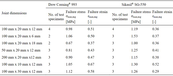
For a better quantitative evaluation of the findings from the tensile tests on linear silicone joints, mean values for failure engineering stress and corresponding engineering strain are provided in Table 4 for each series. The maximum stresses are higher for larger length and width values of the joints, as expected, since the adhesion area gets larger.
However, it can also be observed, that higher engineering stresses can be transferred over a joint with the same adhesion surface, when the joint thickness is reduced.
3.3.Linear glass-stainless steel joints under shear loading
As in the case of the tensile tests on linear silicone joints, the results from the double-lap shear tests are first evaluated in the form of load vs. displacement curves. The results for the specimens with Dow Corning® 993 are plotted in Fig. 9a), while those for specimens with Sikasil® SG-550 are provided in Fig. 9b). Excluding the load cycles, an almost linear development of the experimental curves can be observed for both silicones. A good agreement between the curves obtained for specimens with the same adhesive and the same joint thickness can be noticed. In the case of the finite element simulations for the specimens with Dow Corning® 993, the curves determined with the hyperelastic material law show a better overall fit.
However, for small displacements a slightly better agreement can be achieved with the linear-elastic material law. In reality, generally, a combined loading by tension or compression and shear is given. Therefore, a non-linear material law as the hyperelastic Mooney-Rivlin model should be used, especially when the deformation behavior of the connection as well as of the system including the connection is of primary interest.For the specimens with Sikasil® SG-550, the results obtained with the linear-elastic material law slightly underestimate the experimental curves up to ~50% shear displacement (displacement in loading direction divided by the initial joint thickness), but above this value they show a good fit. The curves determined with the hyperelastic material law for the silicone, lead to a slightly underestimation of the experimentally reached loads over the entire displacement range.
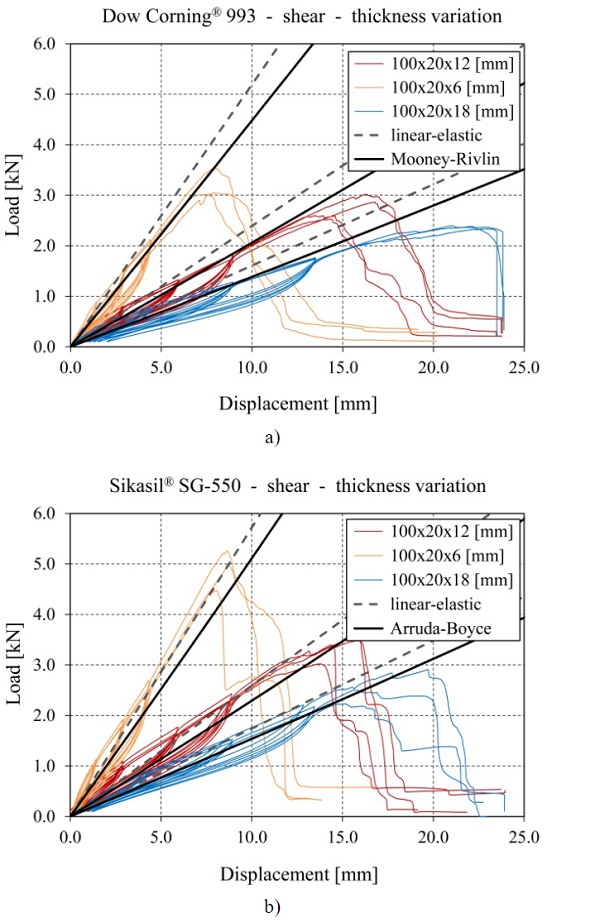
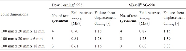
The thickness variation of the linear silicone joints under shear loading has a similar influence on the occurring engineering stresses as in the case of tensile loading. The thinner the joint is, the higher loads can be transferred and implicitly higher failure stresses can be reached. However, it should be considered that thinner joints lead as well to less possible relative displacement between the substrates, which could be necessary for facades when dealing with temperature loads.
Table 5: Mean values for failure engineering stress and corresponding engineering shear displacement from the double-lap shear tests on glass-stainless steel joints.
4.Conclusions and Outlook
Results from experimental and numerical investigations at material level under uniaxial tensile loading and at connection level under tensile loading as well as under shear loading were presented in this research paper for two structural silicones. These two adhesives are considered as potentially suitable candidates for connecting glass panes to a filigree metal framing in a novel concept for glass-metal elements with composite structural behavior.
The objectives of the presented investigations were to analyze the influence of different joint dimensions on the structural performance of linear prismatic joints and to assess the suitability of linear-elastic material laws and especially of selected hyperelastic material laws for predicting the structural behavior of such joints. The experimental results from the tests at connection level show for both silicones that the variation of the joint thickness has the biggest influence on the resulting failure engineering stresses. Both under tensile and under shear loading, higher engineering stresses can be transferred with thinner joints.
The stress vs. strain curves obtained from the uniaxial tensile tests show for both silicones a discreet S-shaped development with a higher stiffness at low strains, which decreases after strains of around 10-15% and increases again slightly at strains above around 75%. The simulations with linear-elastic material laws are not able to reproduce this development. Therefore this type of material law proves to be unsuitable to model the structural behavior of the two silicones under tension. This is also shown by the simulations of the linear joints under tensile loading, where the results obtained with linear-elastic material laws underestimate the experimentally recorded loads at small displacements and increasingly overestimate them at larger displacements. The load vs. displacement curves from the shear tests on linear silicone joints show an almost linear development. Therefore, a linear-elastic material law might be sufficient for simulating such a joint. However, it should be considered that in practice, generally, a combined loading is occurring.
The selected hyperelastic material laws with a maximum of two parameters seem to fit well the overall shape of the experimental curves from the uniaxial tests. However, they are also not able to reproduce the S-shaped development, which results in an underestimation of the stresses at low strains. For a better fit, material laws with more parametersare required. Nevertheless, the simulations of the linear joints with Dow Corning® 993 by using the Mooney-Rivlin model for the silicone show a good overall fit for both tensile and shear loading, in most cases. Only for small displacements, the loads are underestimated, especially under tensile loading.
However, such a model might be sufficient for most situations. For the joints with a thickness of 6 mm, the simulation significantly overestimates the experimental results. Due to the thin joint, the resistance of the stiffer substrates has a bigger influence on the joint deformation and therefore the volumetric part of the strain energy formulations might be required to be considered for thin joints. The simulations of the joints with Sikasil® SG-550 by using the Arruda-Boyce model for the silicone show a good qualitative fit for both tensile and shear loading, but in both load cases and for all the different joint sizes the loads reached in the simulations are lower than those determined experimentally. Additional investigations at material level and eventually at connection level as well are required in this case.
For a better prediction of the structural behavior of linear silicone joints, additional experimental tests on bulk material specimens would be reasonable. The determination of the coefficients for the hyperelastic material laws based on results from compressive tests and planar shear tests in addition to those from the uniaxial tensile tests is recommended. The investigations in this contribution were performed at ambient conditions of approximately 23°C and 50% relative humidity. An extension of the experimental part in order to assess the influence of different temperatures and ageing conditions on the structural behavior of the silicones should be carried out in a next step, especially for Sikasil® SG-550.
Acknowledgements
This research has been carried out at Graz University of Technology as part of the FFG research project no. 838561. The authors would like to acknowledge the collaboration with Waagner-Biro Stahlbau AG on this research project as well as the financial support from the Austrian Research Promotion Agency (FFG) and from Waagner-Biro Stahlbau AG. Furthermore, the authors acknowledge the support of the Laboratory for Structural Engineering at Graz University of Technology in performing the experimental tests on the glass-stainless steel connections. Sika Services AG and Dow Corning S.A. are acknowledged for providing the adhesive materials as well as valuable recommendations.
References
Abaqus 6.13: Analysis User’s Guide – Volume III: Materials. Dassault Systems Simulia (2013)
ASTM: ASTM C 1401-02 – Standard guide for structural sealant glazing. American Society for Testing and Materials (2002)
ASTM: ASTM D412 – Standard test methods for vulcanized rubber and thermoplastic elastomers – Tension. American Society for Testing and Materials (2013)
Belis, J., Van Hulle, A., Out, B., Bos, F., Callewaert, D., Poulis, H.: Broad screening of adhesives for glass-metal bonds. In: Glass Performance Days, pp. 286-289, Tampere (2011)
Dias, V., Odenbreit, C., Hechler, O., Scholzen, F., Ben Zineb, T.: Development of a constitutive hyperelastic material law for numerical simulations of adhesive steel-glass connections using structural silicone. Int. J. Adhes. Adhes. 48, 194-209 (2014)
Dow Corning: Dow Corning® 993 Structural Glazing Sealant – Two part silicone rubber. Product data sheet, Dow Corning Corporation (2014)
Englhardt, O.: Flächentragwerke aus Glas – Tragverhalten und Stabilität. PhD Thesis, University of Natural Resources and Life Sciences Vienna (2007)
EOTA: ETAG-002 – Guideline for European Technical Approval for Structural Sealant Glazing Systems (SSGS). European Organisation for Technical Assessment, Brussels (2001)
Hagl, A.: Development and test logics for structural silicone bonding design and sizing. Glass. Struct. Eng. 1, 131-151 (2016)
Huveners, E.: Circumferentially adhesive bonded glass panes for bracing steel frames in facades. PhD Thesis, Eindhoven University of Technology (2009)
ISO: ISO 37 – Rubber, vulcanized or thermoplastic – Determination of tensile stress-strain properties. International Organization of Standardization, Geneva (2011)
Mocibob, D.: Glass panel under shear loading – use of glass envelopes in building stabilization. PhD Thesis, Ecole Polytechnique Federale de Lausanne – EPFL (2008)
Nardini, V., Doebbel, F.: Concept for seismic design of structural silicone joints in unitized curtain walling. In: Glass Performance Days, pp. 281-286, Tampere (2015)
Nicklisch, F., Dorn, M., Weller, B., Serrano, E.: Joint study on material properties of adhesives to be used in load-bearing timber-glass composite elements. In: Schneider, J., Weller, B. (eds.) Engineered Transparency, pp. 271-280, Düsseldorf (2014)
Overend, M., Jin, Q., Watson, J.: The selection and performance of adhesives for a steel-glass connection. Int. J. Adhes. Adhes. 31, 587-597 (2011)
Sika: Sikasil® SG-550 – High strength structural silicone adhesive. Product data sheet, Sika Schweiz AG (2016)
Staudt, Y., Schneider, J., Odenbreit, C.: Investigation of the material behavior of bonded connections with silicone. In: Schneider, J., Weller, B. (eds.) Engineered Transparency, pp. 393-402, Düsseldorf (2014)
Van Lancker, B., De Corte, W., Belis, J.: Material properties of a structural silicone for linear adhesive glass-metal connections. In: Bos, F., Louter, C., Belis, J. (eds.) Challenging Glass 5, pp. 363-371, Ghent (2016)
Wellershoff, F.: Nutzung der Verglasung zur Aussteifung von Gebäudehüllen. PhD Thesis, RWTH Aachen (2006)