Introduction
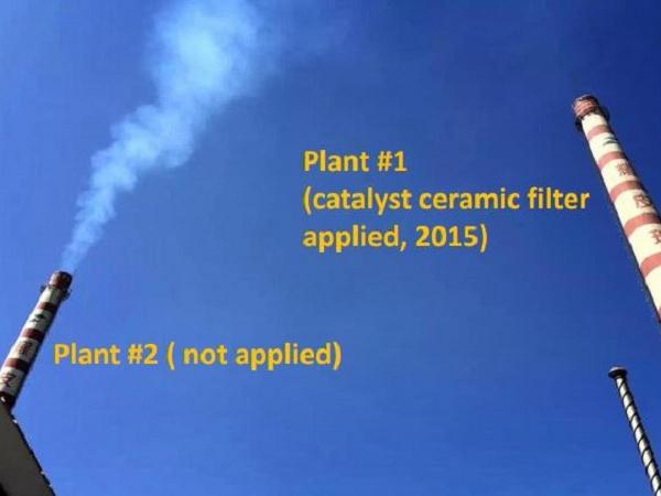
Simultaneous removal of particulates, Nitrogen Oxides and Sulfur Oxides from flue gas can be achieved with catalyst impregnated ceramic filter elements within one housing boxed system. Most of the installed pollution control equipment are dominated by 59% Baghouse fabric filters and 39% ESP‘s.By using a 3 in 1 CCF process there can be a CAPEX savings of 10 to 20% from the traditional ESP/ Baghouse and SCR/SNCR configurations as well as plot space savings. Currently there are 74 glass manufacturing locations in the USA consisting of 133 furnaces of which 42 furnaces have Air Pollution Control equipment installed. 25 of the locations have in operation or are installing CCF units. As more facilities move towards installing or upgrading their units, the CCF base will only increase.
The three most common pollutants found in the air we breathe are Particulate Matter (PM), Nitrogen Oxides (NOx) and Sulfur Oxides (SOx). Nitrogen Dioxide (NO2) is a highly reactive gas or an oxide on nitrogen (Nox). Nitrogen Oxides include nitrous acid and nitric acid. Common types of equipment used to remove NOx are the Selective Catalytic Reduction (SCR) which reacts with Ammonia at around 700 F with the aid of a catalyst and the Selective Non Catalytic Reduction (SNCR) which reacts with ammonia at higher temperatures to reduce NOx.
The United States Environmental Protection Agency (USEPA) regulates all three pollutants. These three major sources of pollutants can trigger respiratory difficulties and asthma as well as cause environmental harms created by acid rain, visibility impairments and water quality impacts.
NOx Treatment
Catalytic reduction of NOx is performed at a typical temperature range between 600 to 700 °F. The NOx reduction operation is performed by injecting an ammonia-based reagent.
In applications with high temperature furnace off gas 1150°F, water spray injection, fresh air dilution or heat exchangers can be used to cool and control the gas velocity and temperature distribution in order to reach the optimum reaction conditions.
SOx Treatment
A group of sulfur oxides (SOx) mainly SO2 are of concern due to creation of sulphuric acids. For SOx removal the commonly used equipment are Wet Flue Gas Desulphurization (WFGD), Circulating Dry Scrubber (CDS) and the Semi-Dry Scrubber (SDA).
The lime reacts in operating temperature ranges between 350F to 1200F with SO2 in order to form salt and water through the following reaction, where calcium (hydrated lime) and sodium based sorbents are used, (sodium bicarbonate or Trona).
PM Treatment
Particulate Matter is a mixture of solid particles, liquid droplets, dust, dirt, soot, and smoke (ranging from 2.5 microns to 10 microns in size) contain base, acids, chemicals, liquids, solids, metal dust and gas particles and are commonly removed using the Baghouse – Fabric Filter or a wet or dry Electrostatic Precipitator (ESP, wetESP). Both limits of particulate matter (PM) such as PM10 (<10 microns) and PM2.5 (less than 2.5 microns) are regulated.
Multi-Polltant Control: 3 in 1
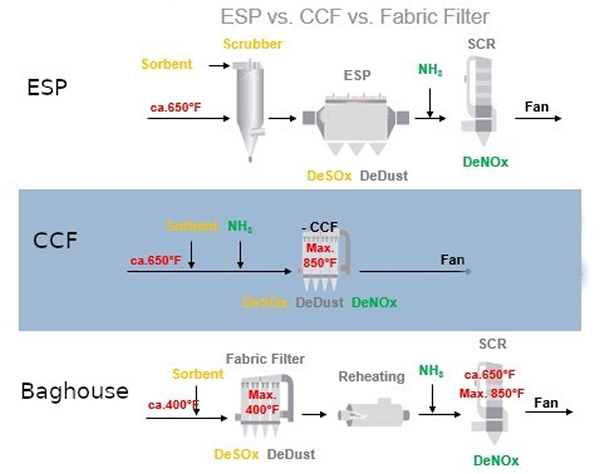
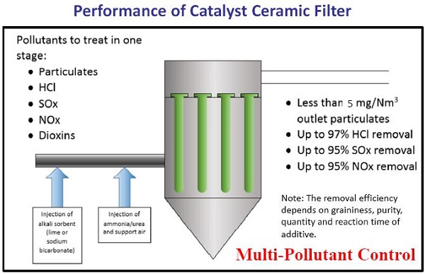
As depicted in Figure 3 , there are three common methods (SCR, SDA, Baghouse) found in Industry to remove NOx, SOx and PM. The various technologies and equipment have been used successfully for pollutant control. The benefit of utilizing ceramic catalytic filters is to reduce the number of equipment being used and hence reduce the onsite footprint. Figure 8 summarizes the removal efficiencies of the CCF unit for various pollutants.
Ceramic Catalytic Filter boxed housing (CCF)
Fabric filters (also called baghouses) and ceramic filters can capture over 99.9% of particulate matter, including PM2.5. These become multi-pollutant systems when combined with sorbent injection to remove additional pollutants, such as mercury, SOx and other acid gases. NOx can be removed via SCR catalysts incorporated in the filter elements and upstream injection of ammonia or, if the temperature is sufficiently high, urea.
Ceramic filters are also called candle filters because of their solid tube shape. The low density ceramic filters can be with and without an embedded catalyst.
The use of catalytic ceramic filter box systems allows for multi pollutant control in one step. The advantages of such a system has been found to be;
- CAPEX savings: Less equipment for PM< NOx and SOx control
- Removal of Dioxins, heavy metals
- Reduced utility usage. Lower pressure drop across the system
- OPEX savings reduced maintenance costs, less equipment to maintain.
- Less moving parts
- High efficiency pollutant removal
- Can run at high exhaust gas temperatures. (> 350 F)
- Modular design: One filter box at a time can be maintained without interrupting operation.
- 5 to 10 years operating life of the catalyst filter elements.
- Filter cake removal is achieved by automatic online pulse jet cleaning
- Operation is away from acid and water dew points
Ceramic Candle Filters
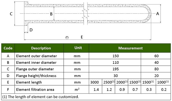
Candle shaped ceramic filters are a rigid tube, 80-90% porosity, lightweight refractory fibers plus organic and inorganic binding agents. Dispersant agents, pore forming agents, high temperature binders and plasticizers are typically added to produce the filter tube allowing for excellent thermal resistance and and thermal shock resistance. High internal surface area exits due to fibre structure. The filters are most commonly supplied in 10 foot lengths by 6 inch diameter with a weight of 12.5 Kg (27 lbs).
Refer to Figure 7 for detailed dimensions. Some suppliers are investigating even longer lengths of 20 feet allowing for less elements per box and hence even lower foot prints.
Low density ceramic filters made up of ~3 µm diameter fibres are vacuum formed into a rigid tube-shaped fibrous filter element from a fibre slurry. The filter elements are installed as an alternative to conventional pulse jet cleaned fabric filter elements.The filter elements are self supported via an integral flange as shown in Figures 3, 4 and 5. The pressure drop across the filter boxes are held at 4“ w.g. when in a clean condition.
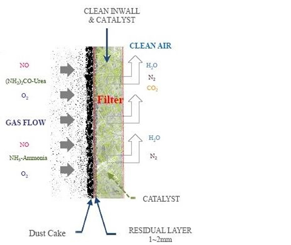
Dry calcium- or sodium-based sorbents are injected into the flue gas upstream of the ceramic filter for SO2 removal. Activated carbon or brominated activated carbon could also be injected to remove mercury. The flue gas is drawn through the filter tube wall by an ID fan where the collected particulates build up as a cake on the outside of the tube (see Figure 6). NOx is removed by catalytic reduction with injected ammonia or urea to form nitrogen and water; the catalyst is embedded within the filter walls. The clean flue gas then passes up the tube into the plenum. The cake is periodically cleaned from the filter walls online using standard pulse jet methods. Optimum pulse jet frequency and pressure improves NOx reduction.
The ceramic filters are spray embedded and dried with a catalyst slurry to allow for reactions to remove NOx. The catalytic filter element consists mostly of Al2O3, SiO3, TiO2, V2O5 and WO3. The micro-sized catalyst particles are distributed across the entire wall thickness, thus creating a large catalytic surface area. Their micro-porous structure and small size partly accounts for the increased reactivity at lower temperatures.
Catalytic ceramic filters have a small footprint and are simple to operate. They could replace an existing ESP and eliminate the need for a separate SCR unit. So they could be retrofitted in Industrial plants where there is not enough space to fit a conventional SCR unit.
The modular design of the box housing units allows filters to be configured to handle large gas flow volumes. The systems can be designed so that a single box can be taken off line if required, and
the remaining two or more boxes continue to operate at a slightly higher pressure without interruption of the process itself and with no appreciable change in emission.
No water is consumed in the process and so no wastewater is produced. However, the fly ash requires disposal. Disposal of the catalytic ceramic filters are required when they reach the end of their life. The catalyst lifetime has been found to be higher than in high dust conventional SCR systems. Typical life of ceramic filters is five to ten years with some installations running greater than 10 years. Ceramic catalytic filters have not yet been used in high dust applications as found in coal fired power plants and cement plants.
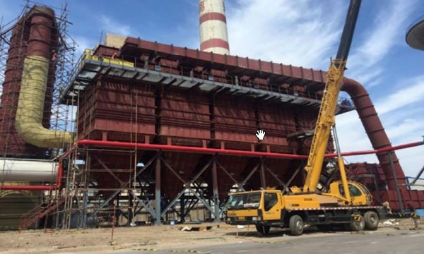
Installation of Filters
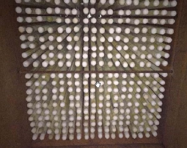
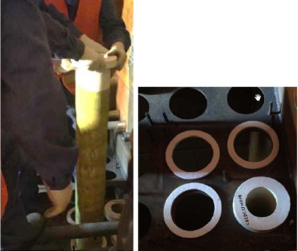
Figure 5: Installed FLK Ceramic Catalytic Filter elements
REFERENCES
Carpenter Anne M (2013) Advances in multi-pollutant control; IEA Clean Coal Centre
Heidenreich S (2013) Hot gas filtration - a review. Fuel; 104; 83-94 (Feb 2013)
Moss K D (2011) Advanced multipollutant control with lightweight ceramic filters. Air Pollution Control; 1(3); 15-19 (Jun 2011)
Moss K D (2012a) Ceramic filter systems. Ceramic Industry; 23-27 (Jun 2012)
Moss K (2012b) Advanced air pollution control in one system. Pollution Engineering; 12-16 (Jan 2012)
Startin A, Elliott G (2009) Controlling emissions with ceramic filters. Chemical Engineering; 35-39 (Jan 2009)