

This paper was first presented at GPD 2023.
Link to the full GPD 2023 conference book: https://www.gpd.fi/GPD2023_proceedings_book/

Authors:
- Timo Bühlmeier - Josef Gartner GmbH
- Jonas Hilcken - Josef Gartner GmbH
Abstract
The use of structural glass elements allows for a tremendous increase in the design freedom of highly transparent glass architecture. Next to the use of jumbo-sized glasses, the connection methodology is the key design driver to achieve maximum transparency and seamless appearance. This is shown in the present case study of the Levitation Ledges at the SUMMIT of the One Vanderbilt Skyscraper, an accessible glass structure at 305 m height above ground. The connections have been reduced to preserve already existing sightlines, which allows an unobstructed view of Manhattan’s skyline. Additionally, these ledges are a thrilling place to be. This paper outlines the design challenge of realizing an ambitious all-glass structure including structural considerations, safety measures, testing sequences and installation method. In addition, a new approach for connecting glass panels, known as the mortise and tenon joint, is introduced.
1. Introduction
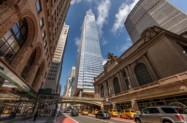
The One Vanderbilt in New York City, located next to the Grand Central Terminal, opened in 2020 and includes offices, retail space and restaurants. With a height of 1,401 feet (427 meters) it is one of the tallest buildings in Midtown Manhattan and provides direct access to one of the city’s largest transportation hubs. The owners SL Green Realty Corp. and coowner Hines developed the building that was designed by the well-known architects Kohn Pedersen Fox. Permasteelisa Group, to which Gartner belongs, was in charge of the entire enclosure system of the skyscraper.
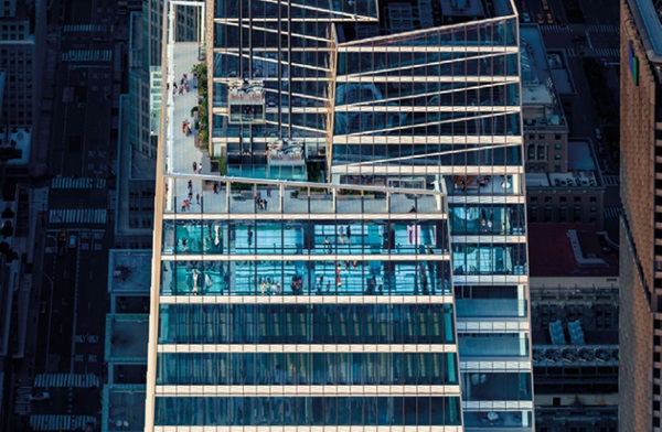
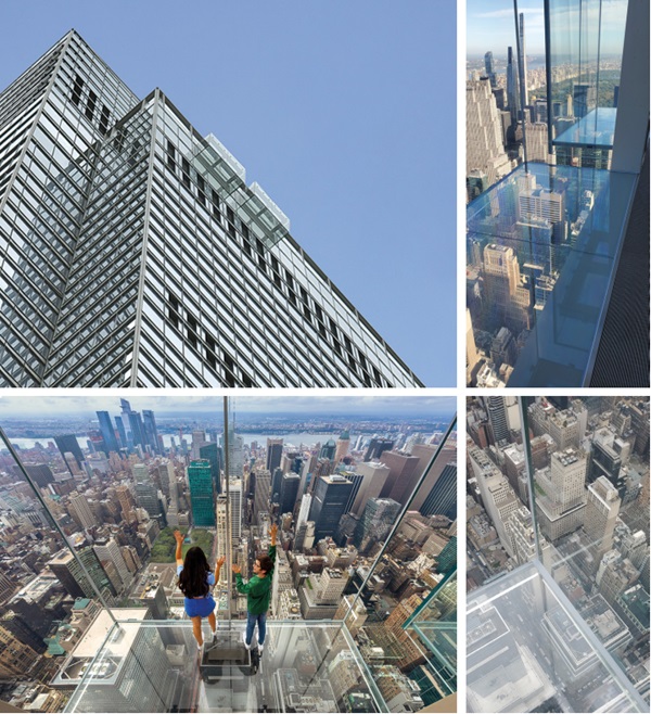
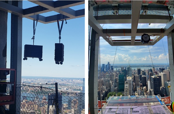
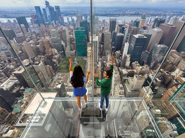
The so-called SUMMIT, designed by Snøhetta, in the upper part of the tower contains several publicly accessible floors, amongst others the indoor observation decks (57th and 58th floor) with the herein described Levitation Ledges manufactured by Gartner and an outdoor observation deck (59th) with exterior glass elevators. The SUMMIT can be described as a signature feature melting art, city and sky in an interactive experience. Next to the art installation AIR, designed by Kenzo Digital, the perception of visitors is further triggered by the Levitation Ledges extending 305 m above Madison Avenue. The two highly transparent accessible all-glass boxes provide absolutely thrilling views and take city perspectives to a new level.
2. Design Challenges
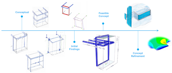
Gartner, in charge of the two Levitation Ledges, entered the project lately in May 2019 with the challenging schedule to be on site in the first half of 2020. It became soon evident that the challenging accessible glass structures with glass floors, cantilevering from the façade line, require a significant period for intense testing. Hence, the conceptual stage and the design development were shortened to a period of two months.
The project started with a well-defined design brief from both the client and the design team, which aimed to design two cantilevered glass boxes. Studies on the functional requirements like observer viewing angles and circulation of visitors traffic through the ledges and the overall SUMMIT served as baseline. The top priority was to achieve a high level of transparency and provide unobstructed views to Manhattan skyline. In order to achieve this, glass had to be used as a key structural component to the greatest extent possible, while minimizing the use of visible connections or inserts where feasible. Here, the focus is particularly on the connections of the glass floor, as these have a significant impact on the view of the streets and the Manhattan skyline.
3. Initial Findings
Initial concepts of the ledges overall structure incorporate curved corner panels that provide significant stiffness to the glass structure, ensuring overall system stability with minimized dimension of the structural elements. However, the use of curved tempered glass, which was structurally necessary, would have compromised the intended clear view due to its inherent physical characteristics resulting from the manufacturing process. Its tolerances and distortion effects are not sufficiently defined by standards [1] and are significantly worse than those of planar tempered glass [2].
Other earlier concepts of the Levitation Ledges used intermediate steel transoms or steel supports at the bottom as structural bracing members, which also partly obstructed the view (Figure 7). To address this issue an all-glass structure was suspended from a cantilevered steel frame at the top by through bolt connections. In this setup, different glass layouts (Figure 7) were explored while using as much in-plane stiffness of the glazing as possible. It was found that lateral loads created high reactions and local stress at the top fixings. Also helpful potential supports at the base of the ledges could not be considered as they attracted the interstory drift to the sensible all-glass structures. Consequently, a full-height, laterally stiff, suspended steel frame was introduced between the facade and the ledges, providing an additional wind support at the base (Figure 8 and 9).
In addition, the minimalist appearance necessitated establishing a balance between performance requirements and envisioned design quality. The following mayor items were mutually agreed upon by the design team and involved stakeholders:
- Relocation of the Levitation Ledges in an area with reduced wind loads as per RWDI Cladding Wind Load Report to simplify glass build-ups and connection details. In the final position, the Levitation Ledges were moved in northerly direction of the west elevation where wind loads (70 psf) are approximately 30% lower compared to the southern extents of the same elevation (previously considered position).
- Limited thermal performance of the glazing, as the complexity of the design could be reduced substantially using laminated glass instead of insulated glass.
- Reduction of reflectivity and glare by using anti-reflective coatings (Planibel Clearsight) on the interior face and exterior face of the laminated glass.
- Appropriate solution providing slip resistance and the client’s safety requirements of the walkable glass floor while maintaining a high degree of transparency (ceramic dot frit).
- Integration of a movement joint taking up differential movements (± 25 mm) between the glass boxes and the adjacent circumferential unitized façade.
In parallel, the lower edge connections have undergone further examination. A rather novel glass connection methodology in analogy to the mortise and tenon joint typically used in timber constructions has been introduced and is discussed in a separate chapter below.
4. Engineering Approach and Safety Concept
To care for the critical nature of an all-glass application an entire finite element model of the structure representing any connection (e.g. bolted connections, silicone joints, etc.) was used already during initial design phase. Additionally, and as current ASTM standards (ASTM E 1300 and ASTM E 2751) do not fully reflect all-glass applications, a safety concept including extensive post breakage behavior testing on a full-scale mock-up (see section below) was developed and cross-checked within the finite element model. The safety concept involves proving the structural integrity in the following post-breakage scenarios:
- Complete failing of individual glass panels: Considering the failure of individual panels supporting the glass floor without taking into account the residual strength of broken elements. In the case of the front panels, even the breakage of both panels simultaneously has been considered.
- Failure of single glass lites: Considering either the exterior or the interior lite of the multi-laminate is broken. In the case of the floor panel, even two broken lites are considered.
- Failure of individual connections: Considering the failure of local supports and the associated structural silicone seal.
The structural evidence of the above was tested in the further course of the project using a full-scale performance mock-up. In addition, a sufficient load carrying capacity and impact resistance has been confirmed as described in the chapter ‘Testing’.
5. Structural System and Final Configuration
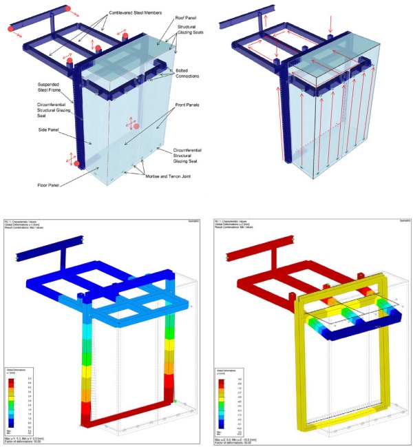
The design driving aspects were merged and created the final configuration of the Levitation Ledges. Each of the glass boxes extending out from the building is 5300 mm high, 3700 mm wide and 1550 mm deep. They are both tophung from cantilevered steel members (RHS 250 mm x 14 mm) [3] that are supported by the building’s primary structure. The all-glass system is connected by means of through bolted glass connections taking up the loads of the glass floor, the vertical façade panels, the roof panel and the suspended steel framing (Figure 10). The latter is made of welded steel box sections (250 mm x 240 mm / 120 mm) and serves as bracing of the lower extents of the glass structure including the glass floor. The entire construction is considered as a self-contained system allowing independent, controlled deflections by a circumferential movement joint and a structurally determined support situation at the same time (Figure 10). Consequently, story drift scenarios have a minimum impact on the glass structure itself.
The key components for the structural integrity are the load-bearing glass panels. They stabilize the lower all-glass part of the structure with their in-plane action. In combination with the novel mortise and tenon glass joint (refer to next chapter) the glazing provides a substantial load path, while achieving the desired overall transparency (Figure 11). The connection itself mainly transfers the live load (100 psf) and the dead load from the accessible glass floor. Lateral loads and wind loads are introduced in the circumferential structural glazing joints at the level of the glass floor and are then further transferred through the floor panel with its diaphragm action. Ultimately, these loads are taken up by the suspended steel framing with its structural silicone joint located in the building’s façade line.
To ensure that the integrated overall system is feasible, it is necessary to consider all connections between glass-glass corners as load bearing structural glazing joints. High wind loads combined with wide spanning glazing lead to substantial structural silicone glazing joint widths of up to 120 mm (DOWSIL 933) which were developed in close collaboration with DOWSIL. The Levitation Ledges two front glass panels and the two side glass panels are made of multilaminates using 4 x 12 mm fully tempered glass and heat-strengthened glass with 1.52 mm SentryGlas® Interlayers. The glass floors are made of 5 x 12 mm heat strengthened glass with 1.52 mm SentryGlas® Interlayers and an additional sacrificial glass lite (fully tempered glass) to prevent damage to the structural laminate in case of severe impacts. The roof panel, 3 x 12 mm heat strengthened glass with 1.52 mm SentryGlas® Interlayers, is structurally sealed to the side panels, front panels and the suspended steel framing.
6. Mortise and Tenon Joint
The connection methodology was an important design driver with the primary concern of how to eliminate and minimize connection elements to an absolute minimum, especially at the lower edge of the glass box. A single structural silicone joint would not be able to take up the forces of the accessible glass floor. Traditional mechanical through bolted connections [4] and adhesive connections would both result in visible connection brackets to transfer loads, even if they can be designed surface flush. Furthermore, the lack of adhesive connections with a demonstrated track record of durability and safety [5] for such critical applications, or those without a supplier's warranty, are a decisive exclusion criterion. Also embedded laminated glass connections with their declining load carrying capacity at increasing temperatures [6, 7] are not considered to be suitable for an extremely exposed cantilevering glass structure.
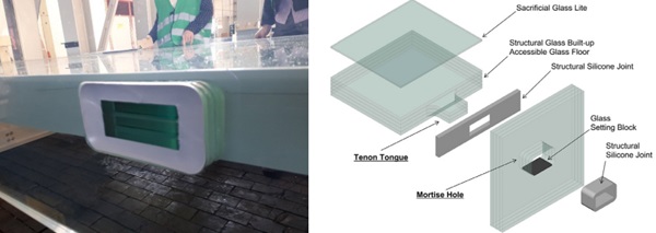
Accordingly, the rather novel mechanical glass-glass connection approach using the mortise and tenon methodology was proposed. It can be applied by working almost with the existing sightlines of the two connecting glass elements. From the interior, solely some additional glass edges are visible and from the exterior a glass pocket with a silicone seal is observable. The mortise and tenon joint is a mechanical force-fitting connection which has been used for thousands of years mainly in timber constructions. The reasons to transfer its success to other materials are evident: Security, strength and simplicity are inherent characteristics of the interlocking connection methodology. The joint consists of two components: the mortise hole and the tenon tongue (Figures 12 and 13).
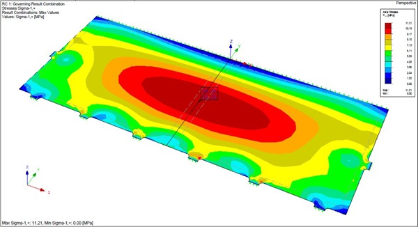
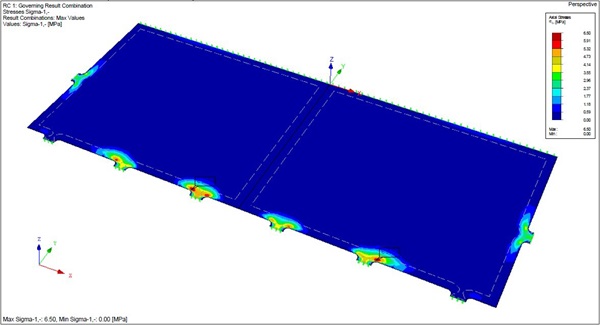
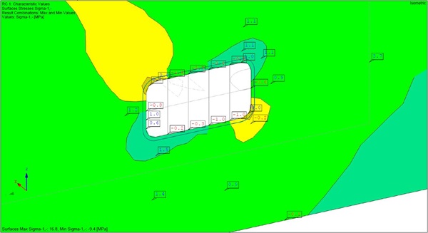
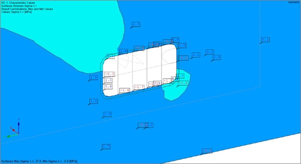
In the case of the Ledges, the mortise hole is a cut-out in the glass surface of the vertical glass panel with a size of 127 mm x 66 mm. The corresponding member, the tenon tongue, is a protrusion from the glass edge of the floor panel fitting into the cut-out (size 100 mm x 39 mm; 3 x 12 mm with1.52 mm SentryGlas®). Structurally the connection works as mechanical locking in vertical directions, the dead load and the live loads of the glass floor are transferred in the vertical glass panels as in-plane loads via glass setting blocks. Wind loads perpendicular to the face panel are transferred by a substantial structural silicone joint along the edge of the accessible glass floor. The maximum stresses occurred at the curved transition (radius 30 mm) of the tenon tongue to the glass floor and in the corner of the mortise hole of the side panels.
The increased magnitude of tensile stress in the tenon tongues of the floor panel (Figures 16 and 17) can be explained by the local load transfer, in combination with the changing main bending direction inducing carding moments [8].
The direct comparison between bolt through connections and mortise and tenon connections confirms that the latter has a higher load bearing capacity (using roughly similar visible surfaces). Specifically, the stress level in the glazing of the mortise and tenon joint was found to be approximately 2.5 times lower than that of the through bolted connection, indicating that this connection method has a promising structural behavior.
Furthermore, the mortise and tenon joint allows the compensation of small production and fabrication tolerances. With the other point connection techniques mentioned above, tolerance compensation is generally not possible. The connection also reacts insensitively to rotations, resulting for example from building movements, whereas strong stresses can occur in the glazing in the case of mechanical or laminated point fixings.
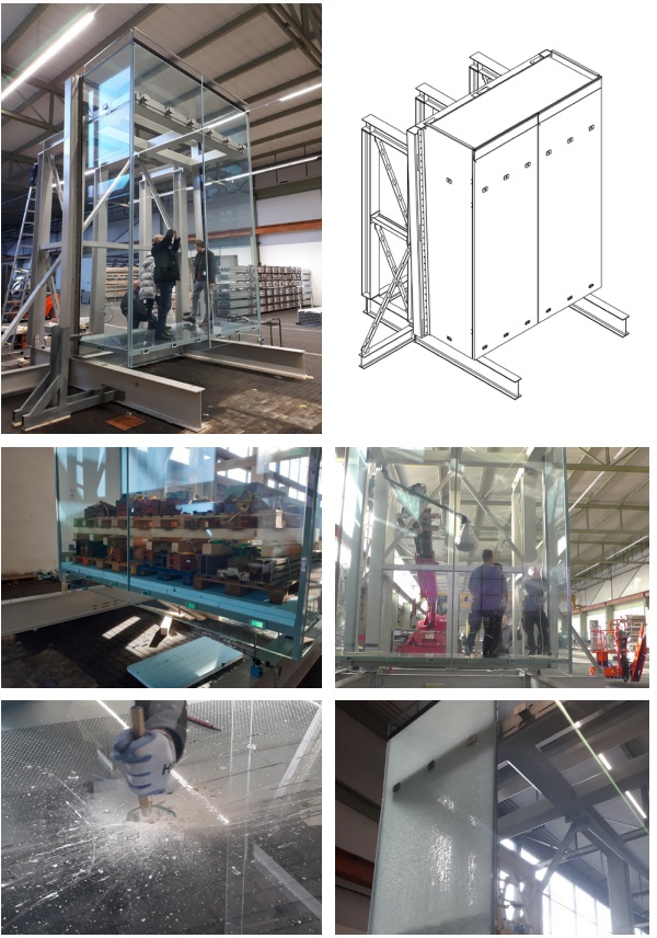
7. Testing
To confirm a sufficient load carrying capacity, impact resistance and post breakage behavior of the all-glass construction of the Levitation Ledges extensive tests were performed on a full size mock-up with the components and materials used in the project. The scope of the tests was beyond the usual safety requirements. In particular, some of the residual load-bearing capacity tests were based on extremely unlikely failure scenarios, thus exploring the limits of the load-bearing capacity.
Impact Tests:
Soft and hard body impact tests according to CWCT TN 66 or TN 76 were performed on all parts (floor, roof, side and front panel) of the Levitation Ledges (Figure 21). In all tests the highest classes according to CWCT TN 66 or TN 76 have been passed. This shows that the glazings of the Levitation Ledges provide a very good resistance to impacts.
Load Capacity Tests:
To demonstrate the sufficient load capacity and to verify the FEM analysis load capacity tests simulating the live load, wind load, dead load and building movements have been performed. Figure 20 shows the live load test with a load of 10 kN/m2 equal to a load of 72 persons or 2 elephants. All elements of the ledges were subjected to at least twice the design load without failure; critical elements were tested until failure. A failure could not be provoked for all parts even subjected to unfavorable conditions. A broken front glazing after a wind load test without structural silicone to the side panel, which in intact conditions transfers a big part of the wind load, could be seen in Figure 23. Using this test, the load capacity of the mechanical point fixings was verified.
Post Breakage Behavior Tests:
The use as viewing platform and the installation location extending 305 m above Madison Avenue necessitate an extraordinary safety concept. Accordingly, the most important part of the test procedure were the post breakage behavior tests by which the residual load capacity of the failed or partially failed structure is shown. Various failure scenarios have been investigated (section 4) – including the improbable scenarios of a total failure of the front glazing and a total failure of the floor glazing. In none of the tests did the glazing fail or did further breakage occur. Accordingly, it could be concluded that the residual load capacity of the ledges is more than sufficient. Another positive side effect of the performance mock-up was that the installation methodology was verified and optimized.
8. Installation
Following the successful testing, manufacturing of all parts commenced immediately. To reduce the need for structural bonding on the construction site, the glass manufacturer accurately bonded the stainless steel profiles in non-visible areas, allowing for screwing them together at the construction site [3]. On site a specific assembly sequence was crucial and had to be carefully planned in detail, always considering the highly sensitive all-glass structure. New equipment was developed and provided to install the complex structure. Mayor sequences were the following:
- Lifting of steel frame and glazing
- Setup working platform and locally required lifting devices
- Installation of cantilevered steel members and vertical steel frame
- Survey and preloading to simulate the selfweight of the glazing
- Installation of floor, side, front and roof panels
- Survey control and fine adjustment
- Structural glazing
- Installation of sacrificial layer
Precise fabrication and quality assurance ensured that all glass elements fitted perfectly into their final positions. Specifically, sliding of the vertical glass panels into the tenons went smoothly as planned.
9. Conclusion
The Levitation Ledges’ complex structural glass assemblies posed multiple challenges, including the need for a holistic structural approach and a visually discreet load-bearing connection. Moreover, a dedicated safety concept for the structure was required and to be verified. Finally, the installation of the components had to be carried out at great heights.
The novel approach of the mortise and tenon connection method has been successfully verified and applied on a project basis. When compared to alternate connection methods, such as bolted or adhesive connections, the glass-glass connection using the mortise and tenon joint could be found to be a safe, strong and reliable option to transfer inplane loads in structural glass elements. The successful implementation of the novel approach was made possible through an in-depth investigation of load paths and a smart combination of the mortise and tenon joint with established structural glazing joints and bolted connections. Furthermore, robust and safe structural glass assemblies were established and validated through fullscale performance testing. As a result, the visitors of the Levitation Ledges at the One Vanderbilt SUMMIT (www.summitov.com) can definitely ‘re-imagine’ the thrill and enjoy an unobstructed view of the Manhattan skyline.
10. References
[1] Schlösser N.: Quality Control and Specification for Distortions of Curved Glass, Glass Performance Days, June 26-28, 2019
[2] Bundesverband Flachglas, BF Merkblatt 009/ 2011, Guidelines for Thermally Curved Glass
[3] Schmitt F., Hilcken J., Zimmermann S.: One Vanderbilt – Ganzglas-Aussichtsboxen für New York, Glasbau 2022, Ernst & Sohn GmbH & Co. KG, March 2022
[4] Haldimann M., Luible A., Overend M.: Structural Use of Glass, International Association for Bridge and Structural Engineering, Zürich, Switzerland, 2008.
[5] Katsivalis I., Feih S.: Prediction of moisture diffusion and failure in glass/steel adhesive joints; Glass Struct. Eng. 7:381–397, August 2022
[6] Santarsiero M., Bedon C., Louter C.: Experimental and numerical analysis of thick embedded laminated glass connections, Composite Structures 188 p. 242-256, January 2018
[7] Santarsiero, M., Louter, C., Nussbaumer, A.: Laminated connections for structural glass components: a full-scale experimental study. Glass Struct Eng 2, pp. 79-101. Springer (2017)
[8] Schober H., Transparent Shells: Form and Typology, Ernst & Sohn GmbH & Co. KG, November 2015


 demonstrator at Glass Technology Live during Glasstec 2024 (© Cas Maertens).")


