
Source:
Challenging Glass 7
Conference on Architectural and Structural Applications of Glass
Belis, Bos & Louter (Eds.), Ghent University, September 2020.
Copyright © with the authors. All rights reserved.
ISBN 978-94-6366-296-3, https://doi.org/10.7480/cgc.7.4662
Authors:
Faidra Oikonomopoulou
Ivneet Singh Bhatia
Felix van der Weijst
Wilfried Damen
Telesilla Bristogianni
Delft University of Technology, The Netherlands

This paper explores two alternative mould fabrication technologies that allow for the casting of (solid) glass components with a great degree of freedom in shape and size and/or of a customized design, in a cost-efficient way. In specific, the paper discusses the research, design and experimental work conducted at TU Delft on 3D-printed sand moulds and adjustable, high-precision steel moulds.3D-printed sand moulds can provide a high-accuracy, cost-effective solution for solid glass components of complex geometry and/or of customized design.
Although this mould technique is already used for metal castings, it remains still unexplored in the field of glass casting. Accordingly, this paper presents the first experimental findings at TU Delft of this mould technology: mould samples using different binders and treated with various coatings for surface finishing are tested in the high temperatures anticipated in glass (kiln-) casting.
Following, 3D-printed moulds are prepared for a given glass geometry and physical glass prototypes are made by kiln-casting. Adjustable metal moulds are another mould technique that offers a degree of freedom in the modulus of a structure. Essentially, components of different sizes and, to an extent, shapes can be generated by the same mould. Accordingly, the design principles and engineering of such a mould and the potential applications and limitations of this technology are discussed.
As a proof of concept, an adjustable mould is made using 3D-printed PLA and laser-cut MDF. The mould is used for the generation of wax models of variable forms, which are used to kiln-cast glass prototypes by the lost-wax technique. Based on the findings on both presented mould technologies, guidelines are given on their suitability according to the production volume, the level of accuracy required and the complexity and variation of forms involved.
1.Introduction
1.1.The shaping potential of cast glass and current limitations imposed by mould technologies
In theory, glass casting, i.e. pouring molten glass into moulds, enables the production of monolithic glass components of virtually any shape and cross-section. Such avast forming potential, combined with the high compressive strength of glass (stated up to1000 MPa for float soda-lime glass by (Saint Gobain 2016; Weller et al. 2008; Ashby, Jones 2006)), offers endless possibilities in the design of diaphanous, monolithic structural glass members of any size and shape: from storey-high glass columns to entire glass envelopes.
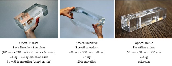
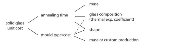
In practice though, the shaping potential of cast glass in the built environment remains largely an unmapped field.The few realized examples of self-supporting structures consisting of cast glass components, namely the Atocha Memorial (Schober et al. 2007), the Crown Fountain (Hannah 2009), the Optical House (Hiroshi 2013) and the Crystal Houses (Oikonomopoulou et al. 2017; Oikonomopoulou et al. 2015), employ identical solid glass units of a simple shape and, roughly, up to 10 kg in mass (fig.1). There are two main reasons behind these design choices for the solid glass units that are also, to an extent, intertwined: (a) the lengthy and perplexed annealing time required for cast glass elements of bigger mass and thickness and (b) the cost barriers imposed by shapes requiring complex high-precision steel or graphite moulds, or by a customized production (fig.2).
The required annealing time can be considered the biggest drawback for the casting of glass pieces of substantial mass. Key factors for reducing the annealing time are the thermal expansion coefficient of glass (directly linked to the glass composition), the mass and overall form of the object (Oikonomopoulou 2019). In this direction, a substantially lighter structure can greatly decrease the annealing time, enabling the fabrication of larger components in a significantly reduced time.
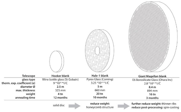
For example, an optimized geometry composed of thinner sections can result in a component of high stiffness and decreased weight. The engineering (and casting) of the massive mirror blanks of the giant ground telescopes is the most characteristic example following this approach: Thanks to its optimized honeycomb structure, each blank of the Giant Magellan Telescope of 8.4 m in diameter and approx. 0.9 m max. thickness required only 3 months of annealing. In comparison, the solid mirror blank of the Hooker Telescope of 2.5 m in diameter and 0.32 m thickness required 12 months of annealing1 (fig.3) (Oikonomopoulou et al. 2018).
1 It should be mentioned here that the glass composition, and specifically the thermal expansion coefficient of the glass used, played a crucial role as well in reducing the annealing time. For the blank of the Hooker Telescope wine bottle glass was used (α=9 * 10-6 1/C), whereas for the blank of the Giant Magellan Telescope, E6 Borosilicate Glass was employed (α=2.8 * 10-6 1/C).
Such optimized geometries require, in turn, complex, high-precision moulds. These, in sequence, result in higher fabrication costs that can jeopardize the market ability of the cast object and render it economically unsustainable. But mould costs can also skyrocket the end-price of customized (non-standardized) components of simple geometry that require high accuracy2.
In other words, for a limited batch of e.g. a hundred units, the cost of a high-precision steel mould can significantly inflate the price of the end product. Hence, currently, the casting of customized glass components is achieved by low-cost, disposable moulds that are, however, labour-intensive and in principle, result in elements of reduced accuracy. In turn, to keep the fabrication costs low, the use of standardized only glass units is currently preferred in architectural applications.
2 Personal communication of the authors with Poesia, the manufacturer of the cast glass blocks of the Crystal Houses façade, suggests that the price of a high-precision mould out of milled stainless steel can be a few thousand euros even for blocks following a simple, rectangular form.
1.2.The potential of adjustable and 3d-printed sand moulds for customized and freeform glass components
In this paper, two alternative mould fabrication technologies are explored as potential solutions to the aforementioned principal challenges (unit size, shape complexity and customization) for the fabrication of cast glass components with a great degree of freedom in shape and size or of, to-an-extent, customized production, without jeopardizing their marketability due to high manufacturing costs. In specific, the paper discusses the research and experimental work conducted at TU Delft on two distinct mould technologies for freeform or customized cast glass components: 3D-printed sand moulds and adjustable, high-precision steel moulds.
Disposable, 3D-printed sand moulds of high accuracy, already used for metal castings, can be employed as a cost-effective solution for the casting of customized solid glass components of complex geometry. Compared to the laborious and time-consuming process of standard investment cast moulds, 3D-printed sand moulds are quick and easy to make and allow for great complexity in shapes, including undercuts and voids.
Such moulds are particularly suitable for casting complex geometries, e.g. such as the ones resulting from a topological optimization design process. To investigate the potential of this mould technology in glass casting, several experiments are conducted at the Glass Lab of TU Delft.
In specific, mould samples printed by ExOne using different binders and treated with various coatings for surface finishing are tested in the high temperatures suitable for glass casting. Finally, based on the chosen binder material and surface coating, 3D-printed moulds of segments of a topologically optimized cast glass column are prepared, and physical glass prototypes are made by kiln-casting.
Adjustable steel moulds can be used to generate components of different sizes and, to an extent, shapes by the same mould, allowing for a degree of freedom in the modulus of the structure. Accordingly, the design principles and engineering of such a mould and the potential applications and limitations of this technology are discussed. As a proof of concept, an adjustable mould out of 3D-printed PLA and laser-cut MDF is made and used for the generation of wax models of variable sizes. The wax models are then used to kiln-cast glass prototypes by the lost-wax technique.
Based on the findings on both novel mould technologies, guidelines are given on their suitability according to the production volume, the level of accuracy required and the complexity and variation of forms involved and suggestions are made on future research directions.
2.Brief overview of current mould technologies
Essentially all moulds for glass casting can be divided into two main categories: disposable and permanent moulds. Table 1 summarizes the characteristics of the prevailing mould types available for glass casting, illustrated in Fig.4. The choice of mould mainly depends mainly on the production volume and the desired level of accuracy of the glass product, and is cost and time driven (Oikonomopoulou et al. 2018).
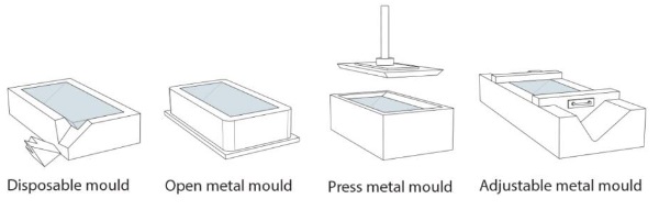
In this direction, disposable moulds (fig.5, left) are preferred for small batch castings or for customized components, as they are significantly cheaper than permanent (metal) moulds. On the downside, disposable moulds, in principle, involve a time-consuming and meticulous labour, require the post-processing of the glass object and compromise the dimensional accuracy of the end product.
More precisely, the precision level and max. melting temperature can vary for such moulds based on the material they are made of, ranging from low-cost investment silica-plaster moulds for castings below 1.000 °C (usually employed in the field of art) to high-cost milled alumina-silica fiber ceramics of top performance (e.g. used for the casting of telescope mirror blanks). In both cases, the glass surface in contact with the mould will obtain a translucent, rough skin that requires post-processing to attain a fully-transparent component. Due to the brittle nature of these moulds, they are commonly used for kiln-casting; hot-pouring is not recommended.
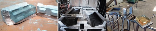
Table 1: Characteristics of prevailing mould types for glass casting derived from (Oikonomopoulou 2019).

For a series (mass) production, permanent moulds from milled steel or graphite (fig.5) are favoured. Hot-pouring can be used with such moulds, which is considerably more time-efficient than kiln-casting. Such moulds (especially pressed-moulds) achieve, in general, a significantly increased dimensional accuracy compared to disposable moulds. A high level of surface detailing can also be directly obtained, particularly when graphite moulds are employed. Overall the resulting surface is glossy and transparent and minimum or no post-processing is required, given that the desired dimensional accuracy is directly met.
Although rarely engineered in such a manner, the permanent moulds can be adjustable if required (fig.5), to allow for shape flexibility (although this may influence the precision level). Finally, although the complexity of the shape is not a significant cost-affecting factor for disposable moulds, it does increase the price of steel and graphite moulds, due to the engineering of sophisticated, multipart moulds.
3. 3D-printed sand moulds for complex shapes and/or customized cast glass components
3.1.Current applications and the potential of 3D-printed sand moulds for glass casting
From the previous section, it can be directly deducted that for cast glass components that follow complex shapes or are tailor-made and where high accuracy is needed, novel solutions need to be developed in order to obtain elements that are cost-efficient in terms of manufacturing costs.
A promising, affordable mould method that can revolutionize the design and production of customized glass components of high accuracy can be found in the development of 3D-printed sand moulds for glass casting. 3D-printers of sand, such as the ones developed and used by 3Dealize, Concr3de and ExOne, are already employed for the production of sand casting moulds for cast metal objects (such as aluminium, carbon steel, stainless steel, bronze, iron and magnesium) of complex geometries of high accuracy (ExOne 2019).
Other advantages of 3D-printed sand moulds include their low cost, quick production (normally limited to a few days), scalability and high size accuracy (up to ± 0.1 mm, defined by the grain size of the sand)3. Typical applications range from the creation of weldless automotive components and propellers to the accurate reproduction through 3D-scanning of damaged or broken elements of old car engines or even of historic structures.
A characteristic example of this technology’s potential is the use of 3D-printed sand moulds for the casting of complex and individually produced steel nodes, developed by Arup and 3Dealise (Niehe 2017). The 3D-printing of the mould was preferred over the direct printing of the node as the latter faces several important drawbacks, such as the lack of certification (due to the inhomogeneity of the printed metal), size limitations and relatively high-costs. Moreover, by printing the mould, additional supports, required during the direct 3D-printing of an object, can be omitted4. Challenging shapes in concrete have also been cast in such 3D-printed sand moulds (Jipa et al. 2016).The largest size of sand mould that can currently be printed using this technique is 4m x2m x 1m by Voxeljet printer VX4000.
Although 3D-printed sand moulds are already employed for the casting of metals with high melting points, so far, in glass, their use is rather limited. Nonetheless, sand casting, which comprises a template (typically made of wood) that is pressed into the sand to make a clear impression, is commonly used by glass artists as a cost-efficient mould solution for casting glass. This technique of low accuracy, however, is not used to produce building elements. Research on the use of 3D-printed sand moulds for glass casting by (Flygt 2018) suggests that this novel mould method can indeed be used as a cost-effective, high-accuracy solution for customized cast glass objects or/and of objects of complex geometry.
There are three principal challenges involved in the application of 3D-printed sand moulds for cast glass components: Firstly, due to the kiln-casting method (used for disposable moulds), the sand moulds should be able to sustain high temperatures for a prolonged period of time (including the annealing process). While sand can easily sustain the anticipated temperatures, the binder’s behaviour is unknown. Subsequently, the mould has to be able to sustain the hydrostatic pressure of molten glass for an equal amount of time. Lastly, due to the mould’s nature, the surface end-quality is rough, thus, it is essential to find a suitable coating to avoid post-processing.
3 Based on personal communication with 3Dealize.
4 These observations are based on personal communication with Arup Amsterdam.
3.2.Experimental investigation
In order to explore the potential of this new mould technology for glass casting, four series of testing are conducted in 3D-printed specimens bonded by different binders at the Glass Lab of TU Delft. An overview of the testing can be found in Table 2. For the testing, 3D-printed sand specimens of 4 different binders were provided by ExOne. All specimens were tested in a ROHDE ELS 200S kiln.
Table 2: Overview of experiments on 3D-printed sand moulds.
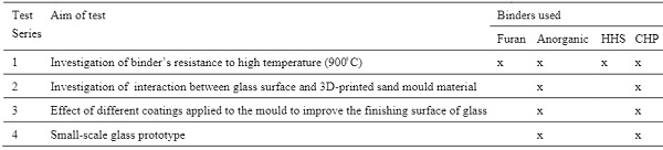
Test Series 1
In series 1, 3D-printed sand bars of 4 different binders are tested up to 900 ̊C in order to investigate their resistance to the high temperatures required for the kiln-casting5 and annealing of cast glass. During the rising temperature, the specimens were regularly checked within the kiln. Table 3 summarizes the main results:
Table 3: Results of 1st Test Series.
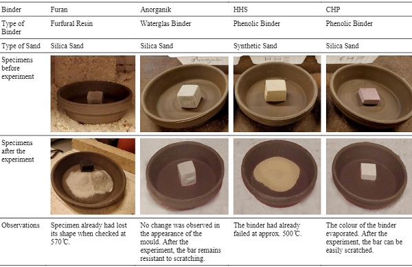
It can be directly concluded that Anorganic and CHP binders are the most promising ones for cast glass applications. Thus, it was determined to use only these two binders for the test specimens of the remaining tests.
5 It should be noted that kiln-casting requires lower temperatures than hot-pouring, since the endothermic chemical reactions linked with glass formation are already complete.
Test Series 2
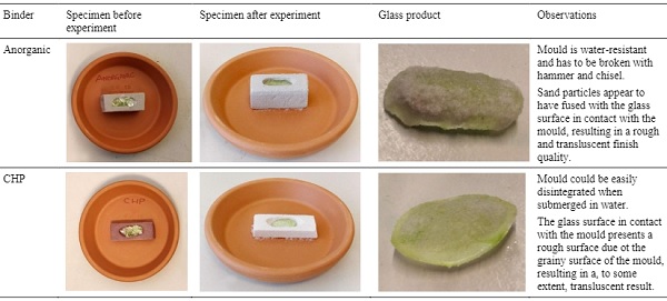
To explore the reaction of glass with the mould material, a small cavity was carved in 3D-printed sand bars made with Anorganic and CHP binder and a glass bead, made of crushed bottle glass, was kiln-cast in them,.
- The following heating programme was used:
- A rising rate of 1 ̊C/min until 780 ̊C
- A dwell (stable temperature) of 90 min at 780 ̊C to allow for the complete melting of glass
- Quenching at a decreasing rate of 2.7 ̊C/min until 430 ̊C
- A dwell of 60 min at 430 ̊C to allow for the glass to anneal.
- Automatic cooling of the kiln after the annealing step.
Once the kiln-casting is complete, the glass is demoulded. A summary of the testing and results can be found in Table 4.
It can be concluded that in both cases,the casting of the glass bead was successful; nonetheless the resulting glass component presents a rough and translucent surface due to the reaction and fusing of glass with the grains of the 3D-printed sand mould. Hence, to achieve a smooth, transparent finishing surface of the glass object, the application of a coating at the mould is deemed necessary.
Table 4: Results of 2nd Test Series.
Test Series 3
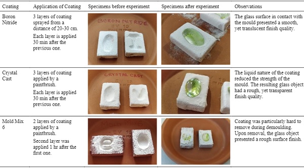
Accordingly, the effect of three different types of surface coatings directly applied on the mould, was investigated on similar specimens and identical heating programme as in test series 2. The selected coatings were chosen based on their direct availability in the Netherlands and low cost, as follows:
a)Boron Nitride
This is a high-temperature release agent which is commonly used in the glass industry. The spraying of the material allows for a uniform surface with a smooth finish. Moreover, owing to the release agent properties, it is anticipated that the glass object can be easily removed from the mould.
b)Crystal Cast
Crystal Castis a powder material, commonly used for creating disposable moulds for glass elements.
c)Mold Mix 6 (by Zircar)
The product is typically used for creating moulds and is available in a paste form.
The results and findings of this series are summarized in Table 5.
None of the tested coatings yielded the desired combination of smooth texture and clear optical quality of the end glass component. In all cases, post-processing of the glass object remains essential in order to attain the desired finish quality. Subsequently, further research is necessary in order to identify a coating fully suitable for a cast glass application. Due to the time restrictions of this research, the 4th test series was conducted using Crystal Cast for coating the moulds as it provided the most satisfying results.
Table 5: Results of 3rd Test Series.
Test Series 4
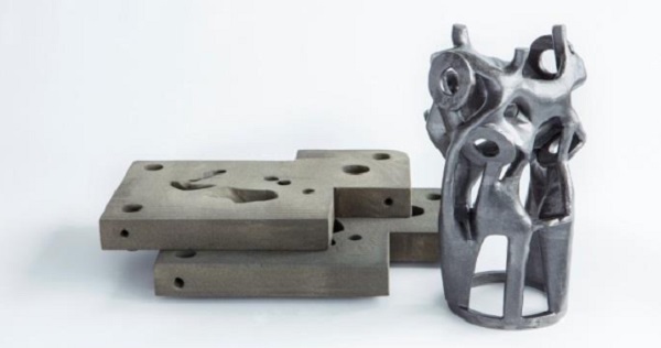
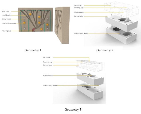
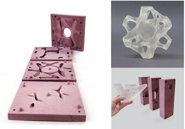
To further explore the feasibility of 3D-printed sand moulds for cast glass components, segments of a topologically optimized cast glass column, developed by (Bhatia 2019), are used for the design of corresponding 3D-printed sand moulds. The moulds, corresponding to3 different segments of the geometry,were produced and sponsored by ExOne (ExOne 2019). The scale of the geometry and corresponding mould size have been constrained based on the size of the available kiln at the Glass Lab of TU Delft. Each mould is made from 2 or 3 slices so that loose sand from the 3D-printing process can be easily removed and there is easy access for a smooth application of the coating.
Interlocking nodes are used to align the different pieces of the mould together. To avoid the opening of the mould due to the hydrostatic pressure caused by the molten glass, M8 steel bolts are used to further stabilize the mould pieces together. To allow for the easy escape of air bubbles, 6 mm in diameter vent pipes have been incorporated to the mould. On top of the mould, a wide opening (pouring cap) has been designed for the inlet of glass. Finally,a 15 mm thick additional boundary has been incorporated to all sides of the mould.
The designed mould geometries can be seen in fig.7. The final, 3D-printed moulds are shown in fig.8. In order to explore the potential of both binder systems, it was determined that geometry 1 would be printed using the Anorganic binder, where as the mould geometries 2 and 3 are made with CHP binder. Prior to casting, all moulds were coated with 3 layers of Crystal Castwith the aid of a paintbrush.
Due to the increased temperatures during kiln-casting, to enhance the safety and robustness of the moulds, a fire blanket has been wrapped around the steel bolts of each mould and the seam between moulds pieces has been sealed with a thick layer of Crystal Castin order to prevent leakage of the molten glass. Lastly, each mould has been encased in a larger silica plaster mould. Coarse compacted sand has been used in between the two moulds. The safety measures can be seen in fig. 9.
Crushed lead glass (cullet) was used for the kiln-casting due to tis lower melting temperature (compared to soda-lime and borosilicate). All moulds were tested under a double annealing schedule reaching a max. T=810 ̊C. The glass cullet was placed inside a flowerpot with a drilled hole at its bottom. The flowerpot was placed with firebricks above the pouring cap of each mould, in order to feed the glass to the mould once it is molten (see fig.10).
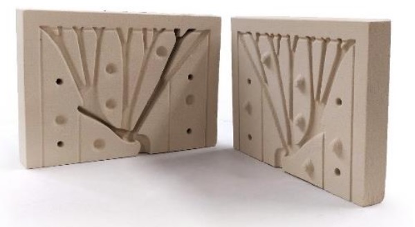
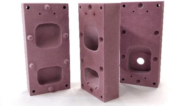
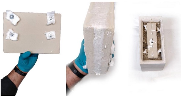
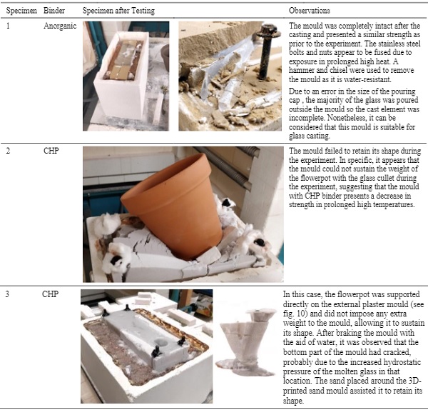
Table 6 provides an overview of the observations derived from this test series. It can be concluded that:
- From the available binders in this research, the anorganic binder can be considered the most suitable option for casting cast glass components of substantial mass. In specific, the mould printed using the anorganic binder was the only one that could successfully withstand the heating cycle without any deterioration of the mould material.
- The results of the mould specimens made with CHP binder suggest that prolonged high temperatures can result in a significant decrease in the strength of this type of mould. In specific, the mould geometry 2 collapsed during the experiment due to the imposed weight of the flowerpot and the glass cullet (see fig.10). The mould of geometry 3, which did not carry any external weight as the flowerpot with the glass cullet was externally supported, still presented cracks at its bottom, due to the increased hydrostatic pressure of the molten glass in this location, leading to glass leakage.
- Besides the composition of the 3D-printed sand mould, several other factors can greatly influence the result of the casting. Namely, it was proven that stainless steel bolts and nuts tend to fuse at the temperatures and prolonged heating needed for the casting of glass. Alternative materials, such as titanium, should be considered for future research. Moreover, it is crucial that the size of the inlet for the molten glass is sufficiently dimensioned to allow for the pouring of molten glass with a viscosity of η=103 –104Pa·s.
- The encasing of the mould in a plaster mould with compacted sand can further assist in securing a successful casting as it can increase its resistance to the anticipated hydrostatic pressure.
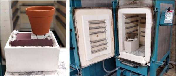
Table 6: Summary of results of Test Series 4.
3.3.Conclusions
Although the presented experiments concern only an initial exploration of the use of 3D-printed sand moulds for cast glass components, the results indicate that this technology is a promising solution for the generation of solid glass components following a perplex or customized geometry. From the tested, available, binder materials, the Anorganic binder yields the most promising results and is considered the most suitable for cast glass applications, as it can sustain the anticipated temperatures for a prolonged period without a significant decrease in strength. Moreover it appears to be able to resist the hydrostatic pressure of the molten glass without deforming or cracking.
The finish quality of the glass that comes into contact with the mould is, in principle, rough and translucent. In consequence, the application of a coating is deemed necessary for achieving a smooth, transparent quality of the finish surface and for preventing the post-processing of the glass object. It should be noted here that the post-processing of the glass component is considered necessary only for attaining the desired visual result and is not needed for the dimensional accuracy of the end product.
Within the context and resources available for this research, the application of Crystal Cast for the coating of the moulds was considered the best available option. Nonetheless, further research is necessary for finding a suitable coating that can result in a completely smooth texture and transparent finish surface.
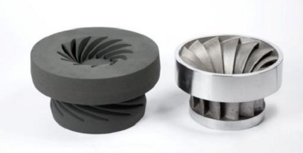
A promising application of such 3D-printed sand moulds is in the casting of topologically optimized glass elements, of reduced mass and larger dimensions, such as the node described in (Damen 2019) and the glass column by (Bhatia 2019) (fig. 11). Essentially, the glass mass can be designed to match design loads whilst keeping the mass homogeneous for even cooling (Oikonomopoulou 2019). The possibility to generate glass forms of reduced mass and complex geometry, not only results in interesting structures but as well in the reduction of the material used and most importantly, of the annealing time involved, allowing for the creation of monolithic glass components of substantial mass in all three dimensions.
4.Engineering of an adjustable steel mould for the generation of components of variable dimensions.
4.1.Existing use of adjustable moulds in glass casting
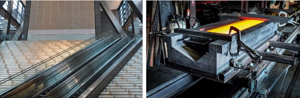
An adjustable metal mould is a suitable solution for reducing the involved manufacturing costs, in applications where components can follow a similar overall geometry with one or two variable parameters. Adjustable steel or graphite moulds already exist in the glass casting industry. The most known example concerns the casting of the glass components of the Ice Falls project in New York, USA, designed by James Carpenter Design Associates Inc.
In this project, all glass elements follow the same general geometry of a prism but are cast in variable lengths. To be able to cast all components with the aid of an identical mould, John Lewis Glass Studio employed an open adjustable graphite mould with a sliding side that can be locked, with the aid of clamps, in any position along the length of the mould (fig. 12). Nonetheless, to the knowledge of the authors, currently adjustable moulds are confined in simple geometries where only one dimension is variable. Therefore, in this paper, an exploration of an adjustable mould that allows for the generation of components that present variable dimensions in two directions (X and Y) is presented.
4.2. Design and Prototyping of an adjustable mould with multiple variables
Case study and design criteria
The presented adjustable mould design concerns the generation of cast glass voussoirs for the construction of a fully transparent shell roof (theoretical case-study) as in (Van der Weijst 2019). A detailed description of the case-study and of the voussoirs’ geometry and division principle can be found in detail at (van der Weijst et al. 2020) in these proceedings. Shell structures follow, in principle, a geometry with varying Gaussian curvature. As a result, the tessellation of a shell results in voussoirs with varying geometry.
It would be financially unsustainable to produce customized moulds (even 3D-printed sand moulds) for each component, given the large amount of components needed. In this case, the design of an adjustable mould that can generate with high-precision all voussoir sizes is more desirable. In order to design such a mould, the following variables have been considered regarding the dimensions of the end component6:
- Edge count
- Edge length
- Interior angles (between the edges)
- Planarity
6 It should be noted that another set of variables has been considered for achieving an interlocking connections of the voussoirs. This is described in detail in the paper by (van der Weijst et al. 2020) in these proceedings. Nonetheless, this set of criteria is deliberately excluded from this paper as the aim here is the investigation of the main geometry only.
Mould Design
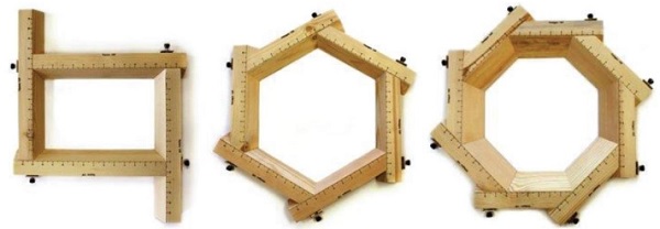
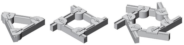
Fig.13 shows three adjustable moulds by Bamboo Tools used in pottery for generating quadrangular, hexagonal or octagonal bowls.The edge lengths can be adjusted to allow for a large variety of shapes to be made by a single mould. The mould is placed on a planar surface that acts as the base of the mould. The adjustability of these moulds is restrained to that of the edge length. Nonetheless, by placing hinges at the vertices, the interior angle can become a variable as well, as shown in fig.14 for triangular, quadrangular and hexagonal shapes.
A vertex module with a bracket hooking on an edge module, can slide along and fixed at the desired edge length. Another edge module can be connected to the vertex module at a variable angle. With this modular system, multiple edge modules can be connected and generate moulds for prismatic polygons of variable edge count, edge lengths and interior angles. T-slots on top of the edge modules allow for the clamping of the vertex modules on the edge modules at any desired edge length with the use of a bolt and T-slot nut (Van der Weijst 2019).
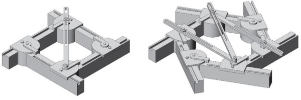
In triangular geometries, with three different edge lengths given as input variables, only one possible triangle can be made. In the case of polygons with more than three edges, additional variables must be given as input parameters for the mould, such as angles or/and diagonal lengths. In principle, any polygon can be defined by a combination of angles and edge lengths.
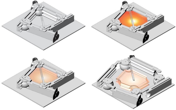
However, since an error in the set-up of an angle can be magnified over distance, higher precision can be achieved by adding diagonals to an adjustable mould instead of setting up the angles, as shown in fig.15. The mould can be placed on a planar base. Although the base, can in theory, be adjustable as well, consisting for example from a flexible surface placed on a grid of pistons (which should be able to withstand the high temperatures during casting), it would result in an exceptionally complex mould. Therefore, it is more realistic to assume that the planar surface will remain identical in order to avoid extreme complexity during production.
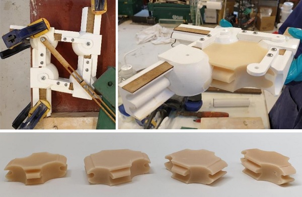
Prototyping
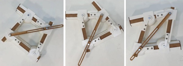
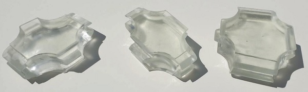
The proposed casting process utilizing the designed adjustable mould can be seen in fig.19. Due to financial and time restrictions it was not possible to fabricate a metal prototype of the designed mould. Instead a prototype was made using 3D-printed PLA and laser-cut MDF (fig. 16) and was used for the generation of wax models of variable sizes, as shown in fig. 17. The wax models are then used to kiln-cast glass prototypes by the lost-wax technique (fig.18).
4.3.Conclusions
The presented adjustable mould highlights the potential of this technique for the creation of high-accuracy cast glass objects that present variable dimensionsin more than one direction. Due to time and financial restrictions, the designed mould was not made by stainless steel or graphite as intended, but instead by 3D-printed PLA and laser-cut MDFand was used to produce wax moulds that were in turn used as the prototype for cast glass objects employing the lost-wax technique. Nonetheless, through the design of this mould it was discovered that although it is possible to make an adjustable mould that can vary in dimensions in both the x and y direction, a mould that would as well address the third dimension would be of extreme complexity. If the principle of an adjustable mould is taken into account from the design stage, glass structures with variable units can be realized with a limited number of moulds, reducing the involved costs and thus, securing their economic feasibility.
5.Conclusions and Discussion
The exploration of two novel mould technologies has been presented in this paper in order to tackle one of the most restricting aspects of producing perplex or customized (solid) cast glass components: the cost of a high-accuracy mould. Both technologies exhibit great potential for cast glass applications and can yield cast components of high dimensional accuracy.
Indeed, cast glass components of a comparative dimensional accuracy can be achieved by either of the proposed methods. Each mould technology, however, is more suitable for adifferent range of cast glass components. In specific, 3D-printed sand moulds can be used for producing complex customized geometries or geometries with undercuts and thin walls that cannot be made with permanent metal moulds. A suitable application of 3D-printed sand moulds is for the production of customized cast glass components that are optimized according to the anticipated loads, allowing in this way for a reduced mass andthus, annealing time.
Other applications concern one-off castings, even of simpler forms, or castings of components of a substantial volume, due to the inherent scalability of this mould technology. Further research is necessary in order to apply this mould technology in glass casting, exploring in mode detail the various mould parameters. The most important drawback of this mould technology at this stage, is the need for post-processing in order to achieve a fine finish surface quality. Thus, the investigation and identification of a coating that allows for a completely smooth and transparent surface quality is of crucial importance for the industrial application of 3D-printed sand moulds for glass casting.
Adjustable metal moulds, made from stainless steel or graphite, are a suitable solution for cast glass applications where the individual units present variable dimensions, yet follow the same principal form. Through the design of an adjustable mould for voussoirs for a glass shell it was underlined that an adjustable mould is a feasible solution for components of variable dimension in two directions (in this case, x and y), however, an adjustable metal mould addressing all three dimensions (x,y,z) would be extremely complex; not only to produce but also to use.
In an adjustable mould, both the edges and the angles can be engineered to be variable. For higher accuracy of the end component it is recommended to add diagonals to control more precisely the desired dimensions, instead of attempting to set-up the angles in precision. Although the designed prototype was not made of metal, the authors are confident that a mould technology such as the one designed can be easily applied in reality.
Lastly,for the success of any project using cast glass, it is of crucial importance that the mould production method is already considered during the design stage so that design decisions can be taken in respect to the manufacturing method.
6.Acknowledgements
The principal findings ofthis paper are based on the MSc thesis of two of the authors. The authors express their deepest gratitude to Andreas Müller from ExOne for producing and sponsoring the 3D-printed sand moulds described in this work. The authors gratefully acknowledge Salome Galjaard from Arup, Amsterdam and Roland Stapper from 3Dealize for their valuable inputon 3D-printed sand moulds technologies and Marcel Bilow from TU Delft for his valuable feedback on the engineering of the adjustable mould.
7.References
Ashby, M.F., Jones, D.R.H.: Engineering Materials 2. An introduction to Microstructures, Processing and Design, 3 ed. Elsevier, UK (2006)
Bhatia, I.: Shaping transparent sand in sand: fabricating geometrically optimized glass column using sand moulds. MSc, TU Delft (2019)
Damen, W.: Structural Glass Gridshell Nodes: designing structural cast glass gridshell nodes using parametric design and topology optimization. MSc, TU Delft (2019)
ExOne: Sand Mould Casting Applications. https://www.exone.com/en-US/case-studies/Sand-Mold-Casting-Applications(2019). Accessed 21st of September 2019
Flygt, E.: Utveckling av 3D-Printade sandformar for glasgjutning. In: GLAS. vol. 4-2018, p. 3. Stockholm, (2018)
Hannah, B.H.: Jaume Plensa: Crown Fountain as Carnivalesque. Umi Dissertation Publishing, USA (2009)
Hiroshi, N.: Residence in Hiroshima. DETAIL: Transluscent and Transparent 2(2013)
Jipa, A., Bernhard, M., Meibodi, M., Dillenburger, B.: 3D-printed stay-in-place formwork for topologically optimized concrete slabs. In: TxA Emerging Design + Technology, San Antonio, Texas, USA 2016
Niehe, P.: Sand printing makes complex casted structural parts affordable. https://www.arup.com/news-and-events/news/sand-printing-makes-complex-casted-structural-parts-affordable(2017). Accessed 19/02 2018
Oikonomopoulou, F.: Unveiling the third dimension of glass. Solid cast glass components and assemblies for structural applications. PhD, TU Delft (2019)
Oikonomopoulou, F., Bristogianni, T., Barou, L., Veer, F.A., Nijsse, R.: The potential of cast glass in structural applications. Lessons learned from large-scale castings and state-of-the art load-bearing cast glass in architecture. J.Build.Eng.20, 213-234 (2018)
Oikonomopoulou, F., Bristogianni, T., Veer, F.A., Nijsse, R.: The construction of the Crystal Houses façade: challenges and innovations. Glass Struct.Eng.1-22 (2017). doi:10.1007/s40940-017-0039-4
Oikonomopoulou, F., Veer, F.A., Nijsse, R., Baardolf, K.: A completely transparent, adhesively bonded soda-lime glass block masonry system. J.Facade Des.Eng.2(3-4), 201-222 (2015). doi:10.3233/fde-150021
Saint Gobain: Physical Properties. http://uk.saint-gobain-glass.com/appcommportalchilddetails/713/442/711/378(2016)
Schober, H., Schneider, J., Justiz, S., Gugeler, J., Paech, C., Balz, M.: Innovations with glass, steel and cables. In: Glass Performance Days, Tampere, Finland, pp. 198-201 (2007)
Van der Weijst, F.: Glass Vaults. Introducing an adjustable mould for casting glass voussoirs for transparent shell structures. MSc, TU Delft (2019)
Van der Weijst, F., Oikonomopoulou, F., Bilow, M.: An Adjustable Mould for the Casting of Glass Voussoirs for the Construction of Fully Transparent Shell Structures. In: Louter, C., Belis, J., Bos, F. (eds.) Challenging Glass 7. Conference on Architectural and Structural Applications of Glass., Ghent 2020
Weller, B., Reich, S., Ebert, J.: Principles and Geometry of Modular Steel-Glass Space Structures. In: Bos, F., Louter, C., Veer, F.A. (eds.) Challenging Glass, Delft 2008, pp. 145-154. IOS Press
Zirker, J.B.: An Acre of Glass: A History and Forecast of the Telescope. The Johns Hopkins University Press Baltimore (2005)


 demonstrator at Glass Technology Live during Glasstec 2024 (© Cas Maertens).")


