
This paper was first presented at GPD 2019 by Frank Seta from Frank Seta & Associates (FSA).
Frank Seta (fseta@frankseta.com) is the President of Frank Seta & Associates (FSA), a pioneering firm in the building envelope industry. For over 35 years Frank has been involved in the design & engineering of thousands of building facades primarily in the NYC metro area. Frank brings both modern and traditional window specification and design concepts to GPD.
Presentation Abstract
This presentation offers a new perspective on limit device design and specifications especially due to construction phase and post-occupancy habits in urban environments. Current standards seem to overlook some critical realities, as will be revealed in the presented cases. This has, in recent times, resulted in a pattern of catastrophic failures. FSA has begun to lay the groundwork for some “thought experiments” regarding why these limit stops are failing.
In addition, this presentation will offer a view into some of the preliminary studies that have been conducted to avoid future failures. These experiments yield some evidence to warrant an evaluation of current limit stop regulatory provisions. The goal, of which, is to improve the correlation of limit stops specifications & testing to the actual installed performance.
Introduction
A large size awning window plummeted from a building in downtown Manhattan. FSA was called in to review the failure and provide feedback. The window met all the standards and codes and had all the necessary documentation. So how could a modern window panel specified & approved to the most current standards & codes exhibit such a catastrophic failure? This and other failure cases are covered in the presentation, along with general findings. This presentation concludes with key takeaways and a call for an industry re-evaluation of current specifications & testing as it pertains to large size operable windows in urban environments.
Presentation Manuscript
Limiting devices were first introduced in 1976 (Walker, 2019). These were more brutish models and their purpose was a means of enforcing child safety in NYC. Today in NYC we reference the health code to specify and design limiting devices (New York City Department of Health). A “limiting device” is usually interfaced with hinge hardware and is comprised of a limiting “arm” to keep the sash from opening beyond 4.5 inches based on the metric of preventing a 5” diameter sphere from passing through the vent opening (New York City Department of Health).
Another key criterion is that the limiting arm be capable of withstanding a 150lb load at centerspan (New York City Department of Health). There are other criteria pertaining to the anchoring of the limit device as well as the stopping device which is what physically stops the window operation.
For this presentation there are three case studies, each from a different project. Project and entity details are left out, but the purpose of this work is to start the conversation. None of the information presented is meant to be used as a scientific or analytical reference. Furthermore, please note that the context for these ideas is specific to the greater NYC region and may not be applicable to other geographical contexts.
Case Study 1
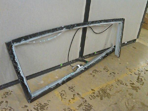
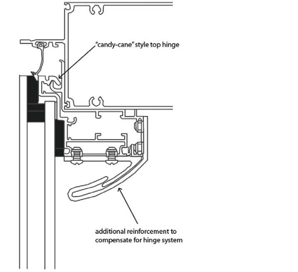
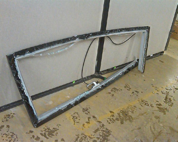
The first case study is an older awning type window design that featured a “candy-cane” top hinge (Figure 1) and poor hardware. There were witnesses to the failure of the vents, these were described as a sucking or rush of air thru the closed vent, after which the closure mechanism failed, the vent flew open, damaging the limiting device, the vents flopped down violently on the façade. In one case this violent flapping caused the vent itself to come apart at the head frame miter joints and the head extrusion to remain on the building. In another case the violent flapping caused the reinforced continuous hinge at the head to open and the vent to fall (Figure 2).
The vent is held in the closed position on the wide vents by 3 points at the bottom of the sash. The latching hardware features a one button catch in the middle of the sash and 2 extending pins which extend into catches mounted to the jambs. The vents are wide, and the sash frames appeared vulnerable to disengagement of the middle button type catch by deflection/torsion. Additionally, some of the hinge hardware was comprised of plastic components.
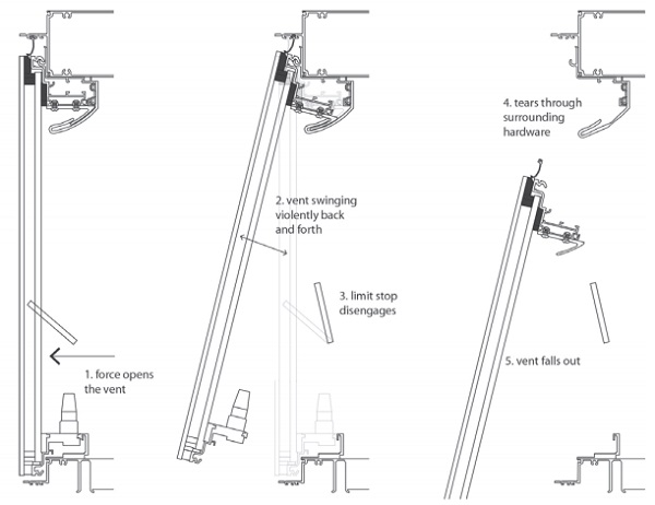
The working theory was based on the notion that the window was initially closed and opened on its own. In this case the limit stop seems to be a secondary failure. There is a critical amount of force required to open a closed window. This initial failure progressed through to the limiting device (Figure 3) which is only designed to withstand 150lbs of force based on code. While we had some theories on how that happened, pressure build-up due to stack effect, inordinate storm winds, we focused on providing a solution that could withstand 100mph wind forces at both the latching mechanism and the limiting devices (Khoukhi & Al-Maqbali 2011).
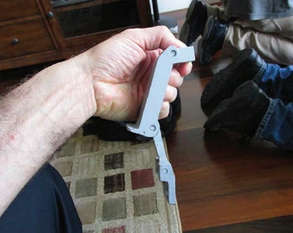
First recommendation was to review the design of the latch mechanism. The manufacturer ended up replacing plastic components with metal and modifying the capture device. Additionally, we recommended to add 2 triple hinged limiting devices at the bottom sash rail (Figure 4). These devices were unique in that they would secure the window while it was in a closed position, and then when operated by an occupant, they would secure the window in the open position as well.
We drafted test criteria to mimic potential forces on the window in a closed and open position. These were meant to simulate approximately 100mph winds. The upgraded limiting device performed as intended and this remedial detail was implemented through the project.
Case Study 2
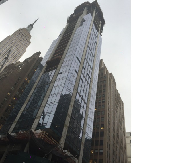
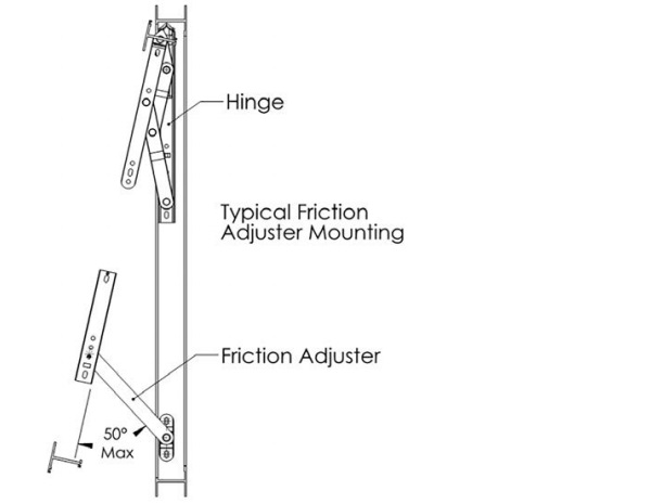
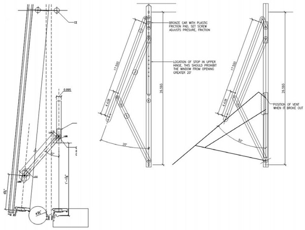
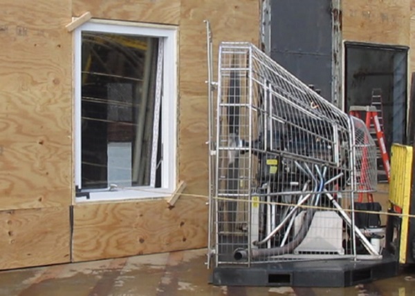
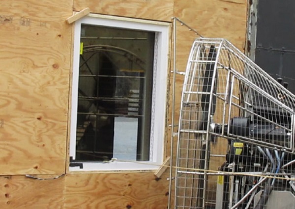
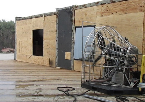
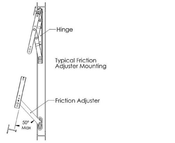
The previous case was of a finished building with closed windows. In this “Case Study 2” the building was partially-unfinished at the area of the “hoist-run” (Figure 5). The vents were 6.5’ tall by 4.5’ wide. The limiting device was incorporated into the hinge design which comprised of 2 “4-bar” hinge assemblies on the upper portion of the jambs and 2 “friction adjusters” on the lower portion (Figure 6).
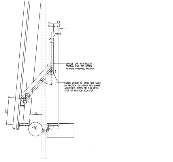
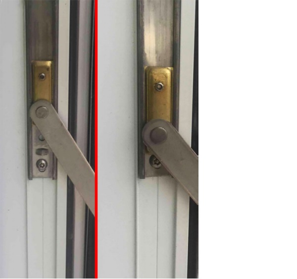
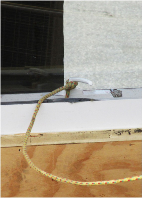
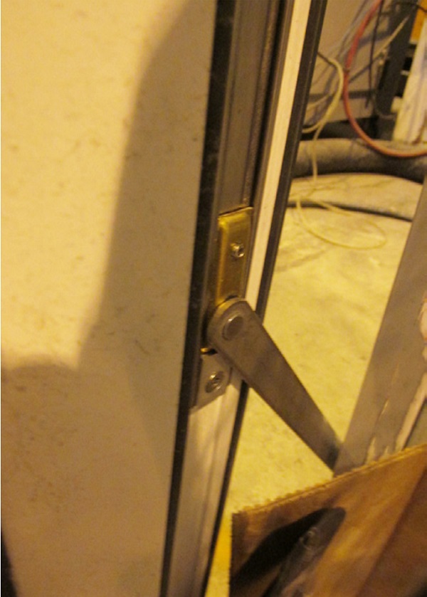
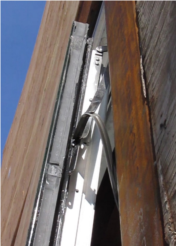
Since this was an active construction site windows were sometimes opened or closed. Although it is always recommended to keep windows closed, it is an unfortunate reality on active projects. The observed failure of these windows was of a “cascading” nature. Firstly, the lower “friction adjustor” (Figure 7) which is a standard hardware component that serves as a limiting device, failed. The sliding assembly pulled over the dimpled metal stop and out of the track, the lower plastic component was sheared off. Also, the lower “friction adjustor” was installed in reverse of what was shown in the shop drawings.
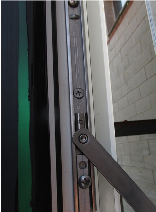
After which the upper hinge “stop”, which is designed to limit the opening of the vent to 20 degrees failed. The stop intended to prevent the vent from opening more than 20 degrees was driven down over the stop dimple in the hinge slide (Figure 8).
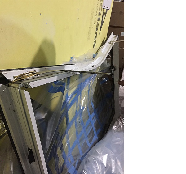
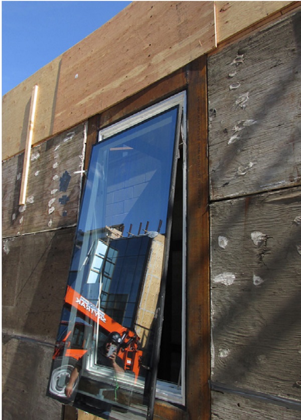
Thirdly, the vent projecting beyond the face of the building, supported by unserviceable and structurally compromised hinges, will not close under its own weight, is buffeted by the wind. Slide track is deformed, and the metal slide is pulled from the track assembly, then the pivot arms fail. And finally, the vent falls (Figure 9 & Figure 10).
There are some complications here as to what really caused the failure. Is it the partially open building creating a compound pressure effect? Are winds blowing through the open hoist run, without interior dampening, overloading unlocked windows and initiating this progressive failure (Flow around Buildings 2015; Parkinson 2015)? Is it the reversed limit stops? Is it all the above?
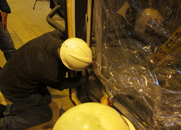
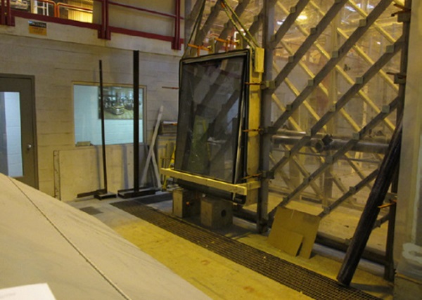
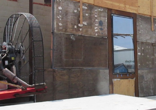
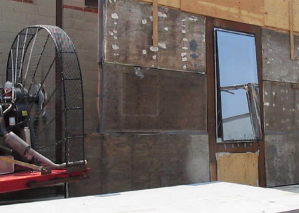
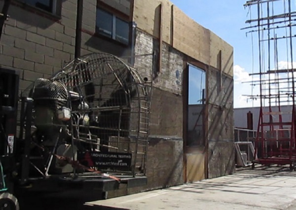
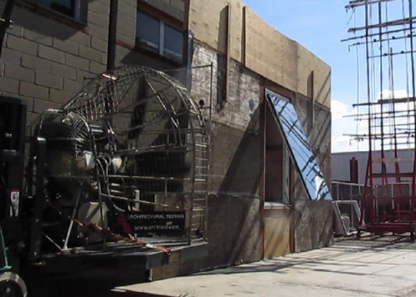
To explore these issues further a series of tests were conducted. These were modified versions of AAMA 910-10, AAMA 501.1, and ASTM E 330. These tests checked the adequacy of the hardware to support the window in a secure manner if the window is left open during a high velocity wind event, durability of the hardware with regards to foreseeable in-service use or misuse and use of new block at limit stop (Figures 11 – 16). The first round of testing was incorrectly conducted, which is not out of the ordinary for modified/new tests that the lab is unfamiliar with. Eventually the testing procedure was properly conducted, and the upgraded hardware passed the tests (Figure 17).
Case Study 3
In the third case study, the vents were of a similar large size awning style (Figure 18) as in “Case Study 2”. The limiting device failed in a similar manner. This was also a building under construction, and we implemented a very similar repair which utilized an aluminum block to prevent the rider from skipping over the stop which was just a small “dimple” (Figure 19). This part of the presentation (Figures 20-25) is included to demonstrate the applicability of the previous lessons learned (this portion of transcript omitted from manuscript).
Final Thoughts
There is a design trend in that awning style windows are only getting larger and larger. Current standards and codes fail to consider potential for progressive/cascading failure of open vents. Sometimes these vents are open during active construction sites, where there is a risk for the geometry of the building to compound the final forces and pressures windows are subjected to. Sometimes, these vents are forced open potentially due to pressurization and other compounding forces. Windows should be designed to anticipate all the realities of construction and postoccupancy.
FSA has begun to lay this groundwork through thought-experiments and preliminary lab test explorations. However, there is ample work to be done across various facets of the industry. During active construction building-interior site dampeners, such as interior walls/partitions can be provided to avoid vent interaction with accelerated winds from the hoist run. Site safety can implement and enforce protocol that prevents anyone from opening windows on the job site. If any windows require opening, that should be limited and then the window locked afterwards.
Specifications can be updated to incorporate a load rating for limiting devices for anticipated loads during window operation. The 150lb force rating only anticipates the human force of operating a window and does not consider potential compound forces from wind and pressure.
Testing can be updated to simulate open vent conditions. On high-rise buildings, where a special wind tunnel analysis is required, models can simulate progression of façade enclosure that create risk, such as an entire vertical strip of the façade remaining incomplete as is the case with the hoist run, and other potential at-risk configurations.
During post-occupancy phase of the project. Warnings can be issued to residents to avoid leaving windows open prior to a major storm or high-wind event.
These series of catastrophic failures are deeply worrying. Luckily, none of these events resulted in injury or loss of life. But that very well could have been the case. The industry must come together to implement appropriate designs, standards, testing, and protocols to ensure the performance of limiting devices in large-size awning type windows in all project realities.
References
“Flow around Buildings.” Autodesk Support & Learning, Autodesk, 12 Feb. 2015, http://knowledge.autodesk.com/support/flow-design/learn-explore/caas/CloudHelp/cloudhelp/ENU/FlowDesign/files/GUID-3B35931F-AB23-45E9-BFCA-2E578D26BF3Ahtm.html
Khoukhi, Maatouk, and Asma Al-Maqbali. “Stack Pressure and Airflow Movement in High and Medium Rise Buildings.” Energy Procedia, Elsevier, 14 June 2011, www.sciencedirect.com/science/article/pii/S1876610211014603
New York City Health Department. Health Codes and Rules. Retrieved from https://www1.nyc.gov/site/doh/health/health-topics/window-guards-preventing-falls.page
Parkinson, Justin. “The Problem with the Skyscraper Wind Effect.” BBC News, BBC, 9 July 2015, www.bbc.com/news/magazine-33426889
Walker, R. (2019, March 14). New Code Requirements and Education Aim to Prevent Window Falls. Retrieved from https://windowanddoor.com/article/marchapril-2009/new-code-requirements-and-education-aimprevent-window-falls


