Authors: Anastasios Moumtzakis, Stamatis Zoras, Vasilis Evagelopoulos and Argyro Dimoudi
Source: Energies 2022, 15(14), 5055; https://doi.org/10.3390/en15145055
(This article belongs to the Section G: Energy and Buildings)
Abstract
Windows are responsible for significant amounts of energy loss through typical building envelopes. There have been multiple studies on heat loss through the glazing unit and frame system. This study presents an experimental investigation of a window unit and focuses specifically on the conductance between the structural elements and the frame system of a conventional house in the city of Xanthi, northern Greece. It is obvious that even a perfect window system cannot reduce heat transfer between the base of the frame and the upper surface of the floor. The experimental and simulation procedure of this project includes the installation of an insulating layer in front of the window unit for a variety of frames (solid wood, aluminum, PVC, etc.) at different distances. The main objective of this paper is to determine how effective an insulating barrier can be in respect to different types of frame, glazing, and weather conditions for the control of heat loss. Through the application of this technique, in combination with an appropriate insulating frame and window unit, designers can control the temperature inside the room at close proximity to the windows, in order to contribute to energy saving, aiming towards a building with zero energy demand.
1. Introduction
In the European Union, buildings represent approximately 40% of the Union’s end energy consumption, of which 63% is associated with residential energy consumption [1,2,3], An analysis on cost-effective energy savings indicates that the existing building stock is the area of primary priority for the EU due to its large potential for energy savings. To reduce the impact of energy on buildings, the European Union has introduced a variety of directives on the energy performance of buildings over the years, under the last circumstances and due to international armed conflicts around the globe, households in Europe are dealing with a crucial energy crisis that has been driven to unprecedented levels.
Nowadays, energy saving techniques are the basis for a bioclimatic design aiming at a building of zero energy demand [4]. Conduction through the building elements is one of the main methods of energy transfer, whereby a large amount of energy is lost through windows, and thermal bridges affect the energy balance of the building’s envelope [5,6,7,8,9]. The energy performance level of a building depends to a great degree on the thermal insulation of the partitions that are used, limiting the fuel consumption for heating and cooling, while at the same time reducing gas emissions into the atmosphere. Furthermore, the improvement of building envelope details related to thermal bridges, due to their contribution to energy savings, is known to be critical; a crucial proportion of energy reduction, up to 10%, could be saved (this is comparable to increasing the insulation thickness or/and using windows with excellent standards) [10,11].
Accurate calculations lead to a clear depiction of the problem and help designers to integrate effective solutions. Simulation tools that are implemented in difficult scenarios provide accuracy, speed, and flexibility. The main objective remains the reduction in energy and improvement of energy balance for buildings in the EU, providing a healthy and comfortable living space for residents. The objective of this paper is to investigate the significance of thermal bridges between the window frame and the floor and decrease the risk of condensation and mold growth in the winter season [12]. The installation of an insulating barrier in front of a window unit in a variety of sizes and its effect is the main focal point of this project.
The dynamic effect of balcony thermal bridges preoccupied the researchers who developed several simulation scenarios. The main concern is the restriction of energy losses between the interior and exterior of the building through the construction elements (balcony slab) [13,14,15]. A study that was carried out by Theodosiou and co-authors [7] showed that structural junctions at the building envelope can increase heat transfer to 30%, which results in an increase in the energy demand for space heating. Ge and Baba [16]; Ge et al. [17]; and Baba and Ge [18] investigated the significance of thermal bridges on the energy balance of multi-unit residential buildings (MURBs) using a balcony separator. The simulation focuses on the energy flow that takes place at the inner body of the slab and uses an 80-mm thick EPS separator to minimize the flow of energy.
More specifically, the results showed that U-values reduced by 72–85%. As reported by the study, the lowest percentage of energy savings were in the configurations with the designed balcony sliding door and spandrel panel, which were the weakest performing parts adjacent to the concrete slab, in terms of both nominal U-value and thermal bridging, due to the aluminum frame material. Hence, it is obvious that heat losses occur between the balcony slab, the frame, and the floor. There is a space where the sliding door frame and the elements of the floor are connected. It is known that a common floor usually must cover a 2cm to 13 cm height. This band acts as a new thermal bridge. Murad et al. [19] investigated the use of an insulated curb that was located beneath the sliding door. The insulated barrier was filled with 25.4-mm thick extruded expanded polystyrene (EPS) rigid insulation. Eight different simulation scenarios were used with modifications to the thermal performance.
The results showed improvements in the thermal characteristics and a significant increase in the interior surface temperature. The focus of the current study is the reduction in energy losses through the floor element, the thermal bridging of the sliding door, or the window system. The main objective is the increase in surface temperature and thermal comfort in the interior space using a thermal break, while eliminating moisture and related issues such as the potential of condensation. The specific technique of the insulating barrier is a low-cost, high surface temperature application without the use of a thermal break in the concrete slab. It is more flexible for the thermal break in this study to be implemented with the thermal break in the concrete slab and the insulated curb. The use of this insulating barrier can easily be extended to the inner side of the external walls of a building and be a useful tool for the renovation of current residential stock around Europe.
2. Materials and Methods
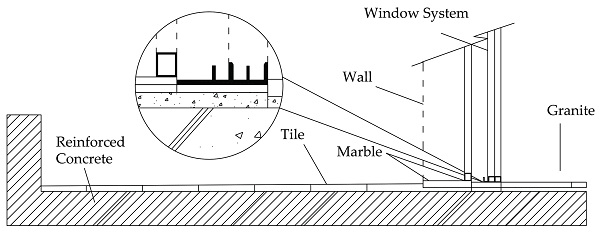
The reduction in energy losses/gains in winter and summer seasons, respectively, is a basic concern of the designers aiming at a building of zero energy demand. This investigation examines the energy balance and improves the basic elements of the building. The project focuses on the heat transfer through the structure elements, especially at the area between the frame of a window and its base on the floor (Figure 1, Figure 2 and Figure 3).
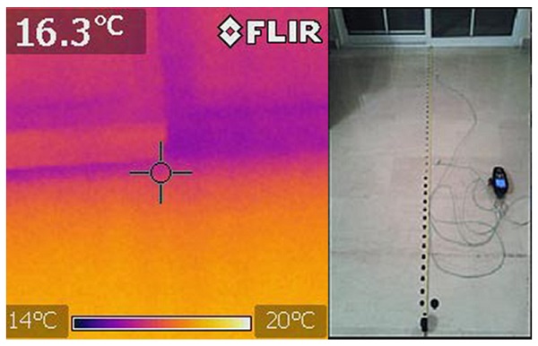
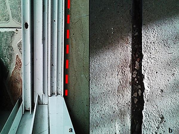
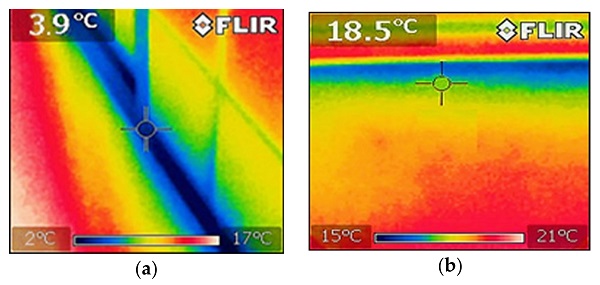
It also examines the correlation between simulated values based on measurements from the experiment using computer software, as well as actual tools. The real values are measured by a thermal camera [20], model FLIR i5, and Kimo Handheld, model TM 200 U, which includes sensors for relative humidity, dew point, and temperature meter (Figure 1). The model is analyzed by sophisticated software. The main tool used is THERM 7.4, a 2-dimensional conduction heat-transfer analysis program based on a finite-element method developed by Lawrence Berkeley National Laboratory [21,22]. The tool is used to calculate the effectiveness of different scenarios of the model. The current model of thermal bridges and boundary settings is been adjusted according to the applicable standards. THERM 7.4 adopts the numerical finite-element evaluation according to the EN ISO 10211 standard using a 2D numerical simulator.
There are two methods for engineers to determine the Ψ value for buildings:
- Numerical calculation solver, according to UNI EN ISO 10211 standard [22];
- Using thermal bridge catalogs, according to UNI EN ISO 14683 standard [23].
Linear transmittance is provided by the following relation:
![]()
Using the value of the linear transmission coefficient of (ψ) for each thermal bridge, it is easy to define the new thermal transmittance for a study area: where L2D is the thermal coupling coefficient that is calculated by the 2D finite element simulation software, Uj is the thermal transmittance coefficient of each building element (j), as it is obtained by a 1D calculation [W/(m²∙K)]; lj is the length [m] and Nj is the total number of 1D elements.
The calculation methodology according to ISO 10211 requires modeling the geometric elements in a way that it is extended by at least 1 m or a triple-thickness of the element part away from the geometrical center of the thermal bridge in the study area:
- The floor slab continued for 3.21 m at the inner side of the residential building (the vertical site of the slab at the inner part of the room was examined as an adiabatic surface);
- Each scenario was analyzed with a balcony outdoor slab length of 2.08 m on the exterior side.
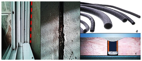
An indoor air temperature of 21 °C in the center of the room, stabilized by an air conditioning system, and an outdoor temperature of −5 °C were used for the simulated scenarios. Improving the structure element at the bottom of the window frame aims to reduce heat transfer using a straight line technique in front of the window system, using an insulating barrier in a variety of thicknesses: 6 mm, 20 mm, and 50 mm (Figure 4).
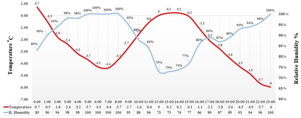
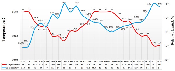
A better U-value frame was calculated in relation to the barrier that improved the structure materials on the floor. The measurements were taken in January 2017 for three consecutive days, the coldest days of the month in the winter period. The daily mean values of the external weather conditions, internal temperature, and relative humidity are illustrated in a diagram in Figure 5 and Figure 6.
THERM’s main components:
- A friendly graphic user interface to design and examine the geometry shape for a given problem;
- A precise mesh generator to create the elements of the model for the finite-element analysis;
- A finite-element calculator;
- An error indicator;
- A view-factor radiation related to the model.
2.1. A 2D Heat Transfer Simulation Analysis Using THERM
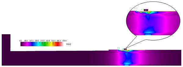
The finite element method (FEM) was used for the 2D heat transfer simulation analysis. THERM is a state-of-the-art software program that is used to model complicated geometries and solve two-dimensional heat transfer issues. It is a sophisticated tool that automatically creates the whole meshing used to model the thermal bridge. The automatic mesh generator uses the finite quadtree algorithm. THERM is an excellent tool that can calculate three basic forms of heat transfer: conduction, convection, and radiation, as well as surface condensation potential in the model. It is worth noting that the given results compare well with experimental results (Figure 7 and Figure 8). The ΤHERM heat-transfer process analysis aims to evaluate a product’s energy efficiency and local temperature patterns, which could be related directly to problems with condensation, moisture damage, mold, and structural integrity.
The basic equation of 2D heat conduction in orthotropic medium Ω under the assumption and examination of constant physical properties is derived from the general energy equation, and is given by the following partial differential equation:
![]()
where K₁₁ and K₂₂ are conductivities in the x and y directions, respectively, and Q (x, y) is the known internal heat generation per unit volume. For a non-homogeneous conducting medium, the conductivities kij are functions of position (x, y). For an isotropic medium, we set K₁₁ = K₂₂ = K in equation (Equation (2)) and obtain the Poisson equation:
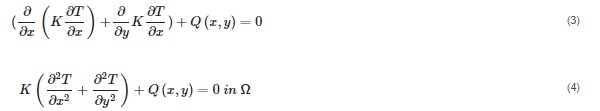
For a medium without an internal heat generation equation (Equation (4)) becomes:
![]()
2.2. The Selected Multi-Unit Residential Building
The selected building is a typical residential Greek multifamily building unit with large apartments, oil-fired central heating systems, five levels, and modernist influences, constructed in 1990–1995.
This building typology integrates the introduction of “Pilotis”, a style of architecture that uses columns or pillars to lift a building above ground, creating free space at ground level that is mainly used as a parking area for MF buildings [24]. According to the Hellenic Statistical Authority (EL. STAT.), almost 71% of Greek buildings were constructed before the implementation of the first Thermal Insulation Regulation (TIR), so emphasis must be laid upon the existing building stock. Furthermore, 83% of this building stock consists of residential spaces, indicating the high potential for energy conservation, while space heating accounts for 67% at the EU-15 level [25,26].
2.3. The Selected Simulation Scenarios Analysis
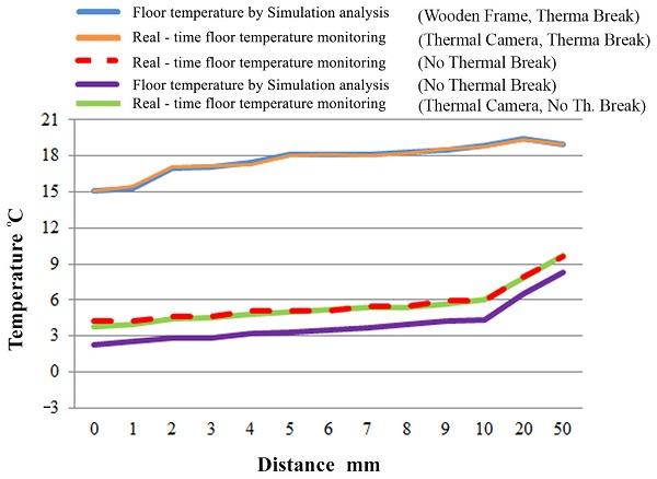
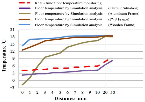
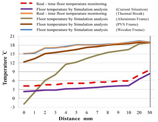
The first scenario analyzes measurements for the current situation: aluminum frame, no insulated barrier, and conventional base for the window frame. The purpose of the renovation of the house is the improvement of the energy identity of the building in accordance with Greek legislation and the Hellenic regulation (KENAK) [27,28]. Measurements on the floor were taken every hour with the Kimo Handheld, model TM 200 U, perpendicular from the frame to the center of the room at a distance of 210 cm (Figure 1). The measured values from the experiment at the second stage are comparable with the simulated values that are calculated with THERM 7.4 software in the second scenario (Figure 9a,b).
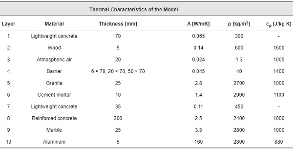
Scenarios with wooden, aluminum, and PVC frames are also examined with an insulating barrier in a variety of sizes: 6 mm, 20 mm, and 50 mm. The main objective is to identify the temperature distributions on the floor, in order to select the appropriate window system. The thermal characteristics of the model are illustrated in Table 1 and Figure 10; the insulated barrier has a low thermal conductivity rate and is placed in front of the frame on the inner side of the room. Construction elements such as window frames and structure materials alternate according to the simulated scenario. The current situation uses an aluminum frame which has a 160 W/mK [29,30] thermal conductivity rate. The aluminum frame material is changed for the fourth scenario and a PVC frame with 0.17 W/mK thermal conductivity rate is used (shown in Figure 11). A fifth scenario uses a wooden frame material with a 0.14 W/mK [29] thermal conductivity rate (shown in Figure 12).
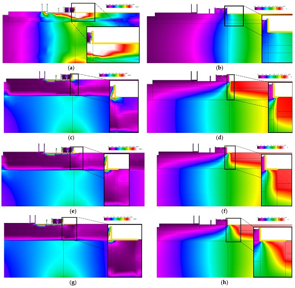
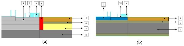
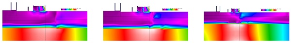
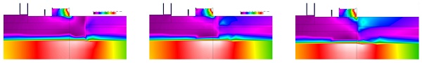
Table 1. Thermal characteristics of the model.
2.4. Reduction in Heat Transfer and Condensation Phenomenon
The 2D simulation scenarios focus on heat transfer through the window frame and the upper floor area, but the influence on the phenomena that are related to the internal surface condensation and mold growth must also be considered [12,31,32]. Condensation occurs in residences respective to the structure of the wall, the window performance, the living arrangements, and the climatic conditions inside and outside of the living space. Condensation occurs when warm, damp air comes into contact with a cold surface. Warm air absorbs much more water than cold air, and when it cools, it reaches saturation, and the water vapor changes into liquid form, settling on the surface itself. The effect of this phenomenon is easily noticeable during the winter period.
The insulating barrier that is placed in front of the window frame aims to reduce the heat transfer from the inner side of the room as the temperature increases near the window unit. It is obvious that when the temperature increases because of the barrier between the window frame and the upper floor area, it is possible for humid air condensation to form on a structure element with a lower energy performance (window units with no good U-Value rate) (Figure 9c–h).
3. Results and Discussion
According to the simulated scenarios and experimental measurements, it is obvious that heat transfer increases in the study area at the first stage of the research (Figure 9a). The main objective is the design of energy-efficient components that attempt to create an insulation barrier. The results show a significant improvement in the point of contact between the windows and the floor, according to the last data results.
3.1. Validation of the System
The process of experimental measurements and model simulations was combined with the use of a thermal camera, which analyzed the area being studied. Thermography detected and recorded the temperatures that developed on the surface of the materials, in order to evaluate the temperature differences in the primary, as well as in the improved state. In studying the primary state (Figure 7), it is obvious that heat loss recorded high values at the point of contact when the temperature was low, which was easily noticeable during the winter months at all of the window frames in the dwelling.
More specifically, the graph in Figure 8 shows a strong correlation between the thermography values and the Kimo Handheld, model TM 200 U, which includes temperature sensors: both tools measure the current situation before the implementation of the insulating barrier at the study area. The average difference between the temperature sensors and thermography is 0.16 °C. Moreover, the same graph presents the improvement of the system between the window and the floor, made by placing the insulation barrier in front of the frame.
The 50-mm thick insulation barrier and the replacement of the aluminum by a wooden frame played a decisive role in increasing the internal temperature, as well as in reducing the heat loss (Figure 7). The illustrated data analysis in the graph between the simulation and thermography have a small average difference of 0.09 °C in temperature reaction. On the other hand, the simulated temperature values in the first part of the study seem to be lower than the real-time measurements due to the gradual aging of the materials.
3.2. Simulated Scenarios and Window Frames
According to the first stage of the analysis, before the improvement of the study area under consideration, heat leakage is significant, and as a result, the presented values are quite high. The first scenario, as already mentioned, has no insulation barrier and the frames are made of aluminum. The obtained values from the examination of the second scenario were recorded by the THERM program using the simulation of the model, while the analyzed data from the first scenario were recorded by measurement devices on site. The technical state of the system was the same. An examination shows that the difference in values between the first and second scenarios was due to the gradual aging of the materials that were used for more than 25 years.
The improvement was evident in the third scenario, where the insulation barrier was applied in combination with lightweight cement under the frame and floor. Although the frame was made of aluminum, it was noticeable that by using the insulation barrier (6 mm), the energy leakage dropped from 1168 W/m2 to 770 W/m2 as the internal temperature rose (Figure 9b), while at 20 °C (Table 2), the end length decreased from 1100 mm to 360 mm. Although the internal temperature values improved, a decrease in temperature (−1.6 °C) was observed at the contact limit compared to the original value (2.3 °C), because the insulation barrier restricted the heat inside the room. As a conclusion, aluminum is cooled by the low temperatures of environmental conditions and develops low temperatures as a good conductor of heat. An analysis of the problem led to the improvement of the structural components of the system.
Table 2. Results and characteristics of the model.
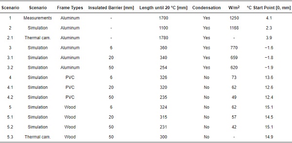
The replacement of the window frame (aluminum) by a PVC frame had a positive effect on energy saving. By examining the PVC frame model, which has better thermal conductivity than aluminum, heat leakage values (W/m²) improved by 90.5% for those using a 6 mm insulation barrier, 90.6% for those using a 20-mm thick insulation barrier, while for those using a 50-mm insulating barrier there was a 92.1% saving. The corresponding increase in temperature at the contact limit is 13.6 °C from −1.6 °C for those using an insulation barrier with a 6-mm thickness (Table 2, Figure 13), 12.6 °C from −1.8 °C for those with a 20-mm thickness (Table 2, Figure 14), and 12.4 °C from −1.9 °C for those using an insulation barrier with a 50-mm thickness (Table 2, Figure 15).
Moreover, on examination of the wood frame model, which has a better thermal conductivity than aluminum, the heat leakage values (W/m²) were further improved. Those using a 6-mm insulation barrier recorded an improvement of 91.9%, from 770 W/m² to 62 W/m² (Table 2). Moreover, the use of a wooden frame with a 20-mm insulation barrier showed a 91.3% decrease, and for a 50-mm barrier insulation a 93.2% reduction. The corresponding increase in temperature at the contact limit position is 15.1 °C from −1.6 °C with the use of a 6-mm insulation barrier (Table 2, Figure 13), 14.5 °C from −1.8 °C with a 20-mm insulation barrier (Table 2, Figure 14), and 15.1 °C from −1.9 °C for those using a 50-mm insulation barrier (Table 2, Figure 15).
3.3. Effects of the Insulating Barrier at the Inner Space of the Room
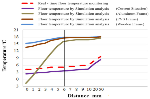
It is obvious that the use of the insulation barrier improves the temperature inside the room. The diagrams depict an abrupt temperature increase at the contact point (position between floor, frame, and barrier) in frames using a low thermal conductivity coefficient, while the aluminum frames show a gradual improvement. Window frames with high thermal conductivity, such as aluminum without thermal break protection, maintain low temperatures and high energy leakage, resulting in the condensation phenomenon. The effect of condensation causes issues for structural elements that often lead to their deterioration. The moisture problem appears in the first five scenarios in Table 2. The insulation barrier reduces energy leakage while having a negative effect on the contact point by lowering the temperature and increasing the probability of condensation. This phenomenon is observed in all three insulation barriers of 6 mm, 20 mm, and 50 mm (shown in Figure 9c–h), with the latter causing the highest temperature drop at the contact point.
4. Conclusions
The analysis of the energy footprint had a significant role in the energy behavior of the living space, especially in the building envelope areas that interacted with the weather. The implementation of the thermal barrier between the floor and the frame was tested with field measurements, as well by using simulation programs demonstrating the positive contribution and energy savings that it can offer. Several research papers examine the thermal barrier between indoor and outdoor spaces because it has a positive effect on the overall energy equilibrium. It is obvious the influence of the upper side of the floor level on the linear thermal transmittance value, as well as the impact of the protected zone (thermal barrier) in collaboration with external partitions for any wall type or window element, to reduce the effect of heat flux. Previous work has shown an improvement in energy leakage with the use of a thermal barrier, while the effect on the heating load for mild climates, and the effect on the cooling load for cold climates were evident.
Moreover, the influence of the frame’s material and its location is technically significant and indicates a large degree of energy reduction. It is obvious the strong relationship between the lower part of the vertical external partition of the window and the barrier at the upper part of the concrete slab on the inner side of the room. The thermal transmittance value of the contact point with frames using a low thermal conductivity coefficient (wood, PVC, etc.) is improved. The vast majority of insulation techniques occur at the external part of the envelope; in general, the literature lacks data analyses for thermal bridges in a variant of connection points between the upper floor thickness (2–13 cm) of the room and the wall or window bases. This study also investigated the main advantages of a thermal barrier, leading to the conclusion that it acts as a neutral zone that can block heat flux from the inner side of the building and also blocks the heat that encounters the external walls or window elements. Additionally, the present study explores the idea of an internal grid of neutral zones inside the floor of the building room, which collaborates with different materials that limit the heat flux.
In the present work, the positive contribution of the thermal barrier is confirmed, as the minimum temperature at the contact point improves from 4.1 to 15.1 °C. This increase in value involves the replacement of the aluminum frame with a wooden frame. A notable improvement in energy leakage is observed from the first use of the thermal barrier (scenario 3), since the energy amount is reduced from 1250 to 770, up to 42 W/m2 at the point of the element’s (barrier) installation. The point that needs attention is that which combines the use of an insulation barrier with old and non-energy-efficient window frames (without a thermal break), as this creates water vapor condensation (shown in Figure 9c–h). Furthermore, analyzing the result data shows that the thermal barrier improves the distance between the frame and floor temperature (20 °C). In particular, it seems that the initial distance values are 1700 mm, while the improved distance state is 231 mm, as specified in Table 2.
Overall, the present technical application of the insulation barrier can work with techniques that are proposed by other researchers, creating a comprehensive framework for resistance to large energy leaks. A key benefit to this construction element is that it is quick, flexible, and economical to install, and is an excellent option for the energy upgrade of buildings that need specific intervention measures as a part of the large building stockpiles with energy issues in the European Union.
Author Contributions
Conceptualization, S.Z.; methodology, S.Z. and A.M.; software, A.M.; validation, S.Z., V.E. and A.D.; investigation, S.Z. and A.M.; writing—original draft preparation, S.Z. and A.M.; writing—review and editing, S.Z., A.M., V.E. and A.D.; visualization, A.M.; supervision, S.Z.; project administration, S.Z.; experimental design, S.Z.; calibration, A.M. All authors have read and agreed to the published version of the manuscript.
Funding
This research received no external funding.
Data Availability Statement
Not applicable.
Conflicts of Interest
The authors declare no conflict of interest.

")