")
Source: Glass Structures & Engineering
Authors: Alberto Consolaro, Massimo Maffeis, Laura Galuppi, Dario Mangoni & Gianni Royer Carfagni
DOI: https://doi.org/10.1007/s40940-025-00309-z
Abstract
The growing interest in space exploration, not least for tourism purposes, requires comfortable and visually engaging accommodations in orbiting stations, with large windows to observe the Earth and the cosmos. While seemingly simple, these elements are complex engineering feats, of paramount importance to enhance both the functionality and the human experience of space missions. Designing space windows requires addressing a unique set of engineering demands to ensure safety, durability, and performance under the extreme space conditions. The key requirement is the capacity to withstand the pressure differential between the station’s interior and the vacuum of space, about two order of magnitude higher than in terrestrial applications, without excessive deformation or failure. Furthermore, the glazing is particularly vulnerable to the temperature variations, from the intense heat of direct sunlight to the extreme cold of space, generating cyclically-varying thermal stress that can damage the materials. Finally, space windows must be designed to handle impacts from space debris traveling at high velocities. Other requirements are resilience, high fracture toughness, high endurance limit and lightweight. For these reasons, space glazing are usually composed of several layers, to provide: radiation/thermal shield (multiple plies, vacuum insulated); structural capacity (redundant pressure panes); protection against debris (external pane) and from scratch (internal sacrificial layer). The state of the art in space glazing is represented by the Cupola of the International Space Station (ISS), made of fused silica monolithic flat panels. To address the unique challenges of the space environment, it is not possible to transfer to this context the glazing technology used for terrestrial applications, and innovative transparent composite are necessary. With reference to the windows of the ISS Cupola, taken as paradigmatic examples, we discuss the design, conception, and modeling of high-performance transparent unitized cells for large spacecraft and space station windows, based on operational thermal, optical, and structural requirements.
1 Introduction
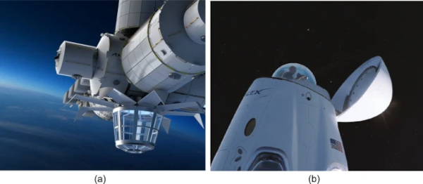
A significant transformation in the space sector is the growing involvement of private investors in an industry that was previously funded solely by public investments. One of the aspects of this change is the rise of space tourism, which demands comfortable and visually appealing environments. This is exemplified by the project of the Axiom Space station (Axiom Station 2025), which features an observatory with expansive glass surfaces, shown in Fig. 1a. These transparent areas are a defining feature of the station, offering both a unique experience and a strong marketing element, since they allow for breathtaking views of Earth and outer space. Similarly, SpaceX has designed a large dome for its Dragon spacecraft, indicated in Fig. 1b, to be presumably made of acrylic glass (SpaceX cupola 2025).
The state-of-the-art in glazing for space application is certainly represented by the Cupola installed on the International Space Station (ISS) (Cupola-ISS module 2025), represented in Fig. 2. This was first conceived in 1987 as a workstation for operating the station's robotic arm, maneuvering vehicles outside the station, and observing and supporting spacewalks. Components of the Cupola were initially fabricated in California, and the windows in New York. The final design and assembly was fulfilled by the Italian contractor Alenia Spazio (now Thales Alenia Space Italia). The Cupola was completed in 2003 and installed in the Tranquility module. The module and the Cupola together costed nearly $409 millions.
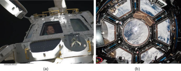
The Cupola's outer framework, represented in Fig. 3a, is made of aluminum from a single forging (no welding), reinforced by an inner skeleton formed by steel plates and bars welded together. The six sides of the Cupola are equipped with trapezoidal shaped windows, whose size is comparable to those of the US Space Shuttle; the circular top window, 800 mm in diameter, currently represents the largest space flight window ever designed (Estes 2002). Each window is equipped with shutters, visible in Fig. 2a, which are closed when the Cupola is not in use, to protect against solar radiation and debris impacts. Figure 3b shows a typical cross section of the Cupola windows. The innermost pane is the “scratch pane”, which serves to protect the other panes and to provide an active heater to prevent condensation. The next pane is the “primary pressure pane” and, behind it, the “redundant pressure pane”. The space between these two panes is periodically evacuated via piping that connects to the external space; hence, in operating conditions, the primary pressure pane is the one that withstands the pressure difference between the inner atmosphere (approximately 1 atm ~ 0.1 MPa) and the outer vacuum. The outermost pane is the “debris pane”, a non-structural element that protects the pressure panes from impacts of micrometeorites, which travel at hypervelocity speeds (Carpenter et al. 2007). The thickness of each one of the pressure panes is 36.8 mm for the circular window, and 25.4 mm for the trapezoidal windows.
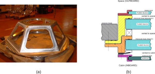
The panes are made of fused silica. The major advantage of this material is that it has a low coefficient of thermal expansion (5.0 10⁻⁷ K⁻¹), which lowers the risks from the stresses induced by an uneven temperature distribution in the panel. Furthermore, it absorbs nearly no radiation and, therefore, is not prone to heating. There are however drawbacks. There is a thermal mismatch between the silica and the aluminum frame due to their differing coefficients of thermal expansion (240 10⁻⁷ K⁻¹ for aluminum), which implies the use of deformable gaskets, subjected to cyclic fatigue. Additionally, fused silica has lower fracture toughness than that of glass. Current fusion technology also makes it extremely challenging to produce large-sized panes. In general, monolithic panels lack robustness, as the appearance of the first crack can lead to failure. Moreover, silica has no static fatigue limit, which can reduce its durability and cause delayed spontaneous fractures. Finally, the material's near-complete permeability to radiation presents potential health risks for astronauts inside the Cupola. This is why, in recent years, the internal scratch panes were replaced with acrylic glass, which absorbs radiation and, as a result, provides shielding for the interior.
Polymeric materials, such as acrylic glass (Poly Methyl MethAcrylate or PMMA), commonly known as Plexiglass, are now preferred over fused silica and other types of glass due to their advantages in weight, cost, shatter resistance, and ease of machining (AlQudah and Freewan 2020). Acrylic glass is not brittle at room temperature, though it has low thermal resistance and is susceptible to degradation, particularly under UV exposure. However, it can become brittle at temperatures below 0 °C and, more importantly, it almost completely loses stiffness and load-bearing capacity near the glass transition temperature, around 100 °C (Richeton et al 2005; Berrahou et al 2016).
The purpose of this article is to address the challenges involved in using transparent materials for space applications, specifically for stations operating in Low Earth Orbit (LEO), and to highlight the key differences in the design of these elements compared to windows intended for terrestrial use. A comparison of materials will be made, focusing on fused silica and acrylic glass, which are currently in use, while also briefly discussing borosilicate glass, which, despite its promising properties, has not yet been applied.
2 Environmental actions and materials
The operating conditions of the International Space Station (ISS) will be considered as a paradigmatic example. The capacity of various materials will be compared with respect to the demand in terms of thermomechanical properties.
2.1 The Low Earth Orbit (LEO) conditions
The ISS operates in Low Earth Orbit (LEO), at an altitude of 370–470 km, with an orbital velocity of 7.6–7.7 km/s, completing the revolution in approximately 90 min. In addition to the pressure load, the window undergoes cyclic temperature variations, which must be accurately considered because they can potentially induce noteworthy thermal stress. Heat convection can only occur in the internal face of the glazing, because there is no atmosphere in the open space. Heat transfer is mainly due to radiation, from three different sources: i) direct radiation from the Sun; ii) sunlight reflection from the Earth’s surface (albedo); iii) planetary radiation from the Earth itself.
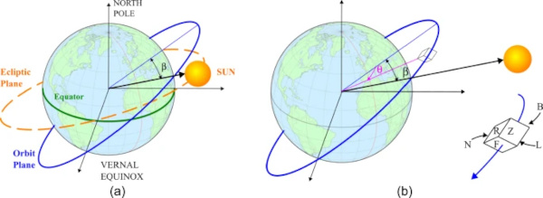
The amount of radiation reaching a window is determined by its position and orientation in space. There is a substantial difference in the condition of a window when installed in spacecraft or a space station. A spacecraft for LEO missions is designed to remain in space for a few days, moving through both sunlight and shadows; it typically executes a “rôtisserie maneuver” during the flight, with a rotation frequency that balances exposure to sunlight and shade. On the other hand, as indicated in Fig. 4a, a space station follows an elliptic orbit in plane, forming an angle β with the axis passing from the centers of the Earth and the Sun. Therefore, the amount of radiation that hit the station depends on the angle β between the orbit plane and the direction connecting Earth and Sun, and the angle θ, indicated in Fig. 4b, which varies with time and defines the position of the station in the orbit plane (Rickman 2014). To define the energy received by a window, one can schematize the station as an “orbiting box”, also shown in Fig. 4b, which determines the Zenith- and Nadir-facing surfaces Z and N, the forward-facing surface F (with outer normal in the direction of the motion), its opposite backward-facing surface B, and lateral Left- and Right-facing surfaces L and R. To each one of these surfaces corresponds a “view factor” (Galuppi and Royer-Carfagni 2025), which determines the radiant energy exchange between two surfaces with different orientation (window and Sun, or window and Earth).
Some practical guidelines, recalled in (Thirsk et al 2009), indicate that, without thermal control, the external surfaces of spacecrafts and space stations can reach the extreme values of 100 °C in direct sunlight, and − 100 °C during orbital night passes in Earth’s shadow. However, these limits are purely indicative. In order to calculate the temperature distribution in the window, it is necessary to perform a transient thermal analysis, considering that the LEO period of revolution is approximately 90 min. The revolution period of the Sun is 24 h, and its orbit plane is subjected to changes. Due to season variation and equatorial bulge, the angle β varies along one year in the range (−75°, 75°). Once evaluated the view factor for each windows (orientations Z, N, F, B, L, R), one can calculate the variation in time of the three radiation sources (Sun, albedo, Earth). The condition β = 0° corresponds to the longest period of eclipse and the highest variation of the solar radiation in time: it provides the greatest temperature changes. On the contrary, for β → 90°, the eclipse fraction is zero and the Sun rays are perpendicular to the orbit plane. When the maximum absorbed radiation is of concern, the limit condition β = ±90° is the most critical.
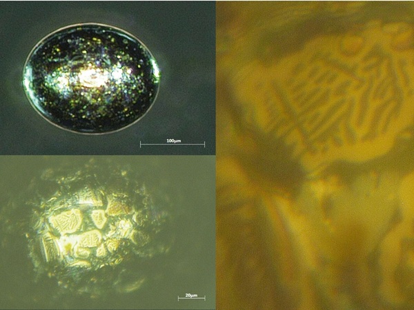
The external pressure is essentially zero (10⁻⁸ Pa): because of this, materials must have low outgassing properties, typically certified by agencies like NASA and ESA. Sealants, gaskets, lubricants, and adhesives are the materials most prone to outgassing, but metals and glasses can also release gases from cracks or impurities. Surface micro-cracks in glass can not only degrade its mechanical properties but also pose a challenge for this issue. Therefore, they must be carefully monitored through stringent production controls and ongoing inspections.
More specifically, the environment cannot be considered a perfect vacuum, as objects in LEO orbit the Earth between the denser layers of the atmosphere and below the inner Van Allen radiation belt. Depending on their orbital altitude, they encounter atmospheric drag from gases in either the thermosphere (approximately 80–600 km above the surface) or the exosphere (around 600 km and higher). All types of spacecraft will be exposed to ionizing particle radiation consisting of atomic and sub-atomic particles such as protons, heavy ions, alpha particles, and electrons. Information and products related to radiation tolerance levels of 300 kRads and higher, are considered sensitive information and are subject to International Traffic in Arms (ITAR) regulations. A particular hazard for materials in LEO is due to atomic (monatomic) oxygen, which is found in the residual low-density portion of the atmosphere. Monatomic oxygen, formed by UV excitation of the O₂ molecule, is highly reactive with many materials, particularly polymers, and can cause erosion from its impact on the rapidly moving spacecraft. In LEO, the typical concentration of monatomic oxygen ranges from 10¹¹ to 10¹² atoms/m³, with atomic energy between 4.3 and 4.4 eV (Banks, 2004).
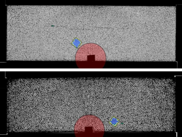
The windows is always potentially subjected to micrometeorite hits during orbit or space travel. Micrometeorite impacts in LEO were measured in the early 1990s, finding that during a 5.75-year exposure time of the testing facility, one impact of about 0.7 mm in diameter per 7 m² of exposed surface area in the Ram direction (estimated rate of travel 10 km/s). This sort of impact could penetrate approximately 2.5 mm of aluminum (McDonnell 1992). The risk analysis is based on probabilistic mechanics and measured data. While sub-millimeter particles are likely to impact the station, they typically do not cause significant damage, whereas larger particles (> 10 mm) can be dangerous but are less likely to strike the satellite. Between these extremes, the combination of particle size and flux plays a major role in determining the failure probability, with the highest risk around 2 mm. It is also important to note that large, potentially hazardous debris—typically remnants from previous missions—are continuously monitored. The North American Aerospace Defense Command (NORAD) began compiling a database following the launch of Sputnik, and tracking systems and databases have since been steadily refined. It should be mentioned, however, that at altitudes of around 400 km or lower, the presence of atmospheric drag helps clear regions of debris.
The environmental conditions described above apply to the operating configuration of the station in orbit. However, the structure must also endure transient conditions during launch, which generate vibrations with accelerations ranging from 3–12 g. Shock requirements are based on the conditions encountered during shipping, handling, launch, and payload separation from the launch vehicle. (NASA, 2017). Windows typically represent weak points in the structure, as they are installed in cavities that disrupt the membrane continuity of the modules. In general, glazing cannot be designed to restore the structural integrity of the load-bearing elements, but they should not be stressed by the deformation of the main structures. Therefore, it is always essential to interpose soft material gaskets between the glazing and the contouring frame. However, our study focuses specifically on windows for orbiting space stations. While some capsules may later integrate into stations, station modules are typically stowed within launch vehicle fairings, shielding them from direct exposure to the external launch environment. Launch qualification analyses are inherently complex and exceed the scope of this study.
2.2 Material properties
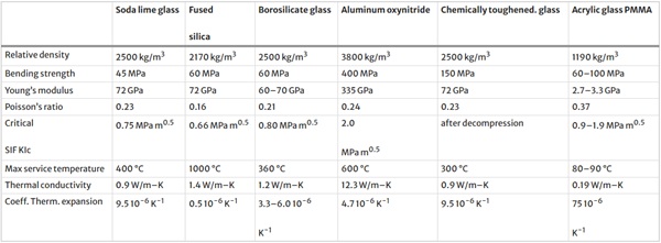
The space glazing built to date is essentially made of two materials: fused silica and acrylic glass. Other materials are sometimes used, or their application is being considered. A synoptic table of the main mechanical properties, which reports average values found in literature but still subject to variation depending on the specific material, is shown in Table 1.
Table 1 Inter-material comparison in terms of mechanical properties - Full size table
Fused Silica (FS), historically used since the Mercury Program and later in the windows of the Gemini, Apollo, Space Shuttle, and International Space Station (Criddle et al 2017; Salem 2017), is a medium refractive-index glass containing SiO2 in the amorphous form, produced by melting high purity silica at extremely high temperatures. FS offers high transparency, very low coefficient of thermal expansion, noteworthy fracture energy and extremely efficient wave transmission on the ultraviolet spectrum (Moore & Smith 2022). However, it is extremely expensive, it has technical limitation in size, and its intrinsic brittleness poses a risk in the event of impact with space debris.
In recent years, acrylic glass (AG), also known as plexiglass, has become the material of choice for spacecrafts such as Orion and Dragon due to its considerable cost and weight advantages. Some companies are exploring the use of AG for the large windows of upcoming space stations operating in LEO. AG is much less expensive than FS, simpler to machine, lightweight, optically clear, UV resistant, and maintains its stability under a variety of environmental conditions, including heat, cold, and humidity. It is not as brittle as glass at room temperature, although the two materials become comparable at temperature below − 50 °C. Furthermore, it is not fragile at room temperature, although it exhibits lower thermal resistance. Additionally, it can serve as a passive shielding material for radiation protection, helping to reduce adverse health effects associated with long-duration space missions (Tomsia et al 2024). For this reason, scratch panes of the ISS Cupola made of fused silica were recently replaced with acrylic glass, and NASA is using acrylic panes to improve the window structural integrity in space vehicles like Orion. However, the mechanical properties of AG are highly sensitive to operating conditions. Its viscoelastic nature—coupled with the wide variety of AG formulations (e.g., additives, cross-linking degrees, and manufacturing processes)—introduces strong dependencies on temperature and load rate. This variability often leads to significant scatter in reported material data across the literature. Its Achilles heel is certainly represented by the sudden decay of mechanical properties at temperatures slightly above 100 °C. There are many types of AGs. One of the most used for space application is ACRIVUE-350S, a lightly cross-linked Poly Methyl MethAcrylate (PMMA) obtained in bi-axially stretched sheets.
Soda-lime glass, commonly used in architecture, is not employed in space applications due to its brittleness, but it has potential for such a use, for its low cost, easy manufacturing in large pieces, temperature resistance. Particularly promising is borosilicate glass, consisting of SiO2 and boron trioxide (B2O3). Its low coefficient of thermal expansion makes it more resistant to thermal shock compared to soda-lime glass. Its chemical durability, mechanical strength, and high softening temperature (Bansal and Doremus 2013) makes it ideal for various industrial, scientific, and consumer applications, such as laboratory glassware and optical components, as lens and mirrors for laser, cameras and telescope (Gusarov et al 2007; Lane 1990). Soda-lime glass can be strengthened through a post-production chemical process that creates permanent surface compression, closing microcracks and enhancing bending strength. This treatment also works for borosilicate glass, although its effectiveness is significantly reduced in glasses containing low Na levels. Chemically strengthened glass fractures into long sharp splinters, similar to float glass, due to the shallow depth of its compressed layer. Essentially, it is a float glass with internal prestress, which has to be considered while assessing the structural capacity.
Transparent ceramic materials are being considered for particular applications for their impressive combination of properties. One of these is aluminum oxynitride (Table 1) also referred to as ALON (Duval et al 2023), obtained by combining aluminum, oxygen, and nitrogen. It is highly transparent to a wide range of electromagnetic wavelengths, including visible and infrared light, very high strength and fracture toughness, resistance to wear and scratching. It is also thermally stable and resistant to high temperatures and harsh environmental conditions. The factors that limit its use are the extremely high cost and the difficulty of processing.
A subtle phenomenon, experienced by most glasses, is static fatigue, due to subcritical crack propagation. Since the material is brittle, the macroscopic strength is determined by the size of microscopic defects. Failure is attained when the flaws reach a critical size and linear elastic fracture mechanics is the most used tool to interpret this effect (Pisano and Royer-Carfagni 2015). However, experiments have provided a wealth of evidence that microscopic cracks can spontaneously grow under constant macroscopic stress, even when their size is far below the critical value predicted by fracture mechanics. It is in general accepted that the velocity of subcritical crack growth is a function of the stress intensity factor, of the type qualitatively represented in Fig. 5a. As characteristic features, one can notice an activation threshold, followed by phase I, where the crack is assumed to propagate due to a stress-enhanced corrosion reaction, strongly dependent upon the environment. In particular, humidity accelerates the process (Ciccotti 2009).
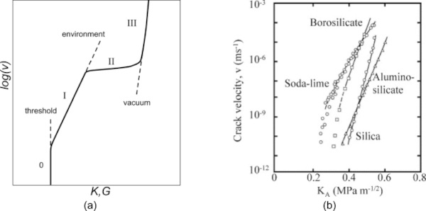
The static fatigue response does depend upon the composition of glass, as shown in Fig. 5b (Wiederhorn and Bolz 1970). In general, glasses with no alkali ions, like silica aluminosilicates, do not give any indication of a fatigue limit, whereas glasses containing alkali ions such as soda lime glasses and borosilicates do exhibit an activation threshold. This phenomenon is potentially critical. Most space windows are made of fused silica: all have a finite lifespan, which depends on the initial crack size and the applied stress, as this material lacks an activation threshold. To assess the lifespan of the element, an initial depth is assumed for a perfect semicircular thumbnail surface crack, and the time required for the crack to reach a critical size under the applied stress is calculated by integrating the law that relates crack propagation rate to the stress intensity factor (Fig. 5a). For the ISS program, NASA/JSC set an initial allowable crack depth of 0.015 mm for the fused silica panes (Estes 2002), determined by expert personnel, and implemented a window inspection certification program to ensure that all individuals handling glass were properly trained, in order to avoid further surface damage. Acrylic glass at ~ 20 °C does not show static fatigue, although the viscoelastic nature of its response needs to be considered.
2.3 Laminated glass
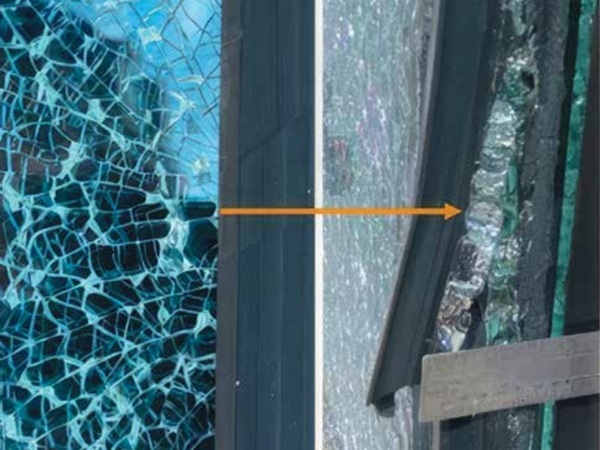
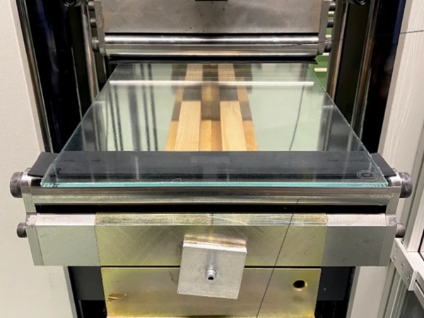
Laminated glass, consisting of glass plies coupled by polymeric interlayers, has noteworthy advantages with respect to monolithic elements. In the pre-glass-breaking phase, thin interlayers can offer the shear coupling of the glass plies, enhancing the stiffness and strength of the laminate. In the post-breakage phase, the glass shards remain attached to the polymer. A residual bending capacity is maintained due to the compression stress provided by direct contact of the glass fragments and the tensile stress in the laminate (Galuppi and Royer-Carfagni 2018). These properties are of paramount importance for space usage. Current spacecraft window designs, such as the ISS Cupola, achieve redundancy by having separate primary and backup pressure panes, as indicated in Fig. 3b. The primary pane carries the pressure load while the backup remains unpressurized and inactive. Laminating the panes presents an alternative load-path: both panes actively share the applied pressure. Compared to uncoupled panes, this shared-load configuration generally improves resistance to static fatigue, since it reduces the stress, and generally results in lighter structures. At the same mass, the transparent element would have a higher load-bearing capacity and provide greater safety in the event of breakage. Recall that the cost of sending 1 kg of mass to LEO is very variable, but of the order of $ 20,000.
In terrestrial applications, commonly used materials for interlayers include Polyvinyl Butyral (PVB), Ethylene Vinyl Acetate (EVA), Thermoplastic Polyurethane (TPU), and ionoplast polymers (Centelles et al. 2020). The coupling between glass layers depends on the shear stiffness of the interlayers but, more precisely, these materials are viscoelastic, meaning their mechanical properties are strongly influenced, besides the duration of the applied load, by the environmental temperature. PVB has high flexibility, strong adhesive properties, good optical clarity, high impact resistance, and effective sound insulation. However, PVB is sensitive to moisture and requires proper sealing. It has a low glass transition temperature, ranging from 25 to 40 °C (Schuster et al. 2018; Centelles et al 2020), and a melting temperature between 165 °C and 185 °C. EVA, a moisture-resistant thermosetting interlayer, with good optical qualities, is often used in photovoltaic panels and environments prone to moisture. The glass transition temperature of EVA ranges from − 40 to − 15 °C, depending on its chemical composition and producer, while the melting temperature lies between 40 °C and 70 °C (Schuster et al. 2018). TPU is a copolymer that combines soft segments for ductility with glassy segments for stiffness. It is frequently used in hybrid components combining glass with PolyCarbonate (PC) or PolyMethyl MethAcrylate (PMMA) layers thanks to its excellent adhesion to both substrates (Centelles et al 2021). It presents a glass transition temperature at − 36 °C (Centelles et al 2020). Ionoplast interlayers provide high strength and stiffness, making them suitable for hurricane-resistant glazing and large-span glass facades. These interlayers maintain clarity over time, and deliver superior mechanical properties. They also have higher transition temperature, between 35 °C and 60 °C (Biolzi et al 2020), with a melting point of 94 °C.
At temperatures above the glass transition temperature, all these materials become very soft and cannot provide substantial benefit in terms of shear coupling or post-breakage capacity. Under particular conditions, the temperature in the glazing due to radiation may exceed the glass transition temperature. Most of all, their durability in the space environment has to be questioned, with respect to out-gassing, UV exposure and the presence of monatomic oxygen in the environment. It’s true that the interlayer is protected by the surrounding glass and that a gasket system typically isolates the panel from the surrounding atmosphere. However, there is usually some leakage in the gaskets, and the edge remains exposed regardless. For these reasons, these materials are generally not regarded as reliable for space applications; certainly, there is no prior experience to support their use.
Indeed, the use of laminated transparent elements in space presents significant challenges, as it introduces new considerations both in terms of selecting materials for interlayers and assessing the technological processes required to fabricate the laminate. Spaceglass Srl and Maffeis Engineering SpA are currently investigating the possibility of using silicone-based interlayers to laminate glass for space applications. Silicone, an inorganic polymer, offers much greater durability compared to traditional interlayers, and some silicone materials are approved by NASA for space use. However, there are several challenges to overcome. First, the lamination technology for silicones differs from the traditional process, which involves high pressure and temperature treatment in an autoclave, and still needs to be finalized. Second, although silicone’s shear stiffness is durable within a useful temperature range (−50 to 100 °C), it typically falls around 1 MPa, which may not be enough to provide significant shear coupling between the glass plies. However, just the behaviour of the laminate at the layered limit (with free sliding glass plies) may help reduce stress in the glass during the serviceability limit state, potentially lowering the risk of static fatigue.
3 Design issues
We present a comparison of materials based on key properties for space window glazing, focusing on mechanical capacity and thermo-optical characteristics.
3.1 Mechanical capacity
To evaluate the possibility of replacing fused silica space windows with alternative transparent materials, it is crucial to determine the pane thicknesses that would deliver equivalent structural performance. As a representative example, we examine the geometry of the largest top window in the ISS Cupola, which has a diameter of 800 mm and features pressure panes that are 36.8 mm thick.
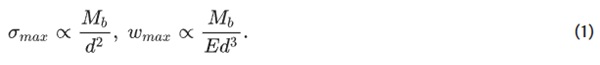
From a structural point of view, the pane thickness can be determined to provide the same deflection, or the same safety factor for the stress, as the actual fused silica pane. In linear elastic plate theory, the maximum stress σₘₐₓ and the maximum deflection ωₘₐₓ under the bending moment per unit length Mb depend on the material elastic modulus E and the pane thickness d. In particular.
By requiring that FS pane and the pane made of a generic material “M” have the same safety factor for stress, and applying Eq. (1), the following result is obtained:
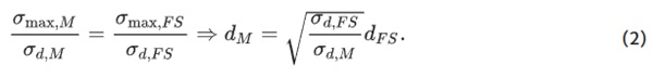
Here, σd,FS and σd,M represent the design flexural strengths for fused silica and the material M being considered, respectively. To achieve the same maximum deflection, the pane thickness can be calculated as
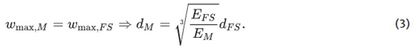
Table 2 shows the pane thickness required to achieve stiffness and strength equivalent to a 36.83 mm thick FS pane, as evaluated using Eqs. (2) and (3), for the various materials listed in Table 1. The table also includes the mass per unit area for each material. Notably, for acrylic glass, a 150 mm thick pane has a mass of 178.5 kg/m², which is considerably higher than the 81 kg/m² mass of a 36.83 mm thick FS pane. Therefore, even if acrylic glass is often considered advantageous for mass reduction, this benefit diminishes if thicker elements are required.
Table 2 Inter-material comparison in terms of pane thickness, mass and cost of lunching, for windows with the same structural capacity of the FS pane used in the largest window of the ISS Cupola - Full size table
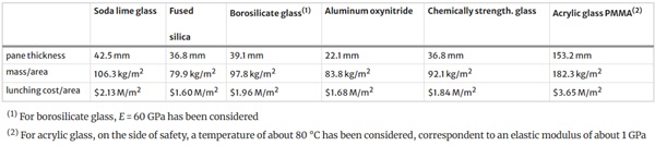
The same table also reports the cost ($M/m²) of launching the glazing into LEO, assuming a unit cost of $20,000/kg. Note that the costs are of the order of millions of dollars per square meter. This suggests that, unlike in terrestrial applications, the cost of float or borosilicate glass would be insignificant, as it is much lower than the transportation cost. Similarly, the potential mass savings can justify the use of very expensive materials, such as aluminum oxynitride. Of course, much depends on the window size, as the cost of glazing made from special materials, such as fused silica or aluminum oxynitride, increases in a superlinear manner with both surface area and thickness. Furthermore, beyond a certain threshold, technological production challenges emerge that currently appear insurmountable. Including manufacturing costs for different window materials in this Table would be insightful, but reliable data are unavailable. This is primarily because these are bespoke components without market prices, and their development costs are typically embedded within larger, contractor-controlled project budgets. For instance, the combined cost of ESA's Tranquility module and Cupola is reported at approximately $409 million, with some estimates placing the Cupola alone near $200 million. However, pinpointing the exact cost contribution of the windows themselves is not feasible.
3.2 Thermal considerations
The operating conditions for windows operating in LEO are more extreme than on Earth because of the high radiation, unshielded by the atmosphere. Design considerations must address thermal stress management, particularly in assemblies (Finckenor 2018), to prevent cracking, crazing and delamination (in case of laminated glass). For window materials, thermal characteristics are as important as mechanical and optical properties. The ideal materials should find a compromise between minimizing heating from radiation exposure (Weston et al 2018) and absorbing radiation to protect astronauts. We set aside considerations related to radiation shielding requirements, which are of paramount importance but involve aspects of human physiology beyond the scope of this discussion. We simply mention that appropriate properties could be achieved with a selective coating, which however leads surface heating of the glass, but this issue will not be addressed here. Active control systems can also be employed to keep the glass temperature within predefined limits, but also this aspect will not be discussed. Therefore, we will focus on the transient thermal analysis of a simple glazing operating in LEO, concentrating on fused silica and acrylic glass, the two most commonly used materials in space applications.
Uneven temperature distributions can induce thermal strains that may lead to thermal stresses exceeding the material's strength (Foraboschi 2017; Galuppi and Royer-Carfagni 2023; Haydar et al. 2024). Additionally, differential thermal expansion between the window and its surrounding frame can lead to excessive stress and fatigue in the gaskets. Therefore, left aside all other issues, from a purely structural point of view the best materials for windows are those that heat up the less under radiation.
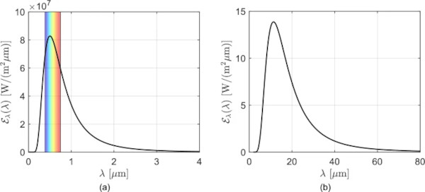
In thermal analyses for terrestrial applications, average coefficients for the thermal properties of the glazing, as well as average values of incident radiation, are typically used. However, for space windows, it is essential to consider the properties associated with each wavelength of the radiation spectrum, based on electromagnetic wave theory. This is because material absorption varies depending on the wavelength of the radiation. The emissive power for solar and albedo radiation is illustrated as a function of the wavelength λ in Fig. 6a, with the range of the visible light evidenced; the corresponding plot for the Earth’s radiation, primarily distributed in the infrared spectrum, is shown in Fig. 6b. For each material, it is necessary to evaluate the effects of electromagnetic radiation at each wavelength individually, and combine them for the whole specturm. While Galuppi and Royer-Carfagni (2024) applied this method to fused silica and a specific acrylic glass, it can be extended to any material if the complex refractive index (real and imaginary parts) is known. We note, however, that literature data are often fragmented and contradictory, underscoring the need for experimental validation.
The solar and albedo radiations are absorbed throughout the volume of the element, with their intensity decaying along the plate thickness coordinate according to an exponential law. For terrestrial glazing, it is common to approximate the absorption profile as constant (Galuppi and Royer-Carfagni 2022). However, in space applications, accounting for the exponential decay is essential due to the significant thickness of the panes and the wide spectrum of radiations involved. In (Galuppi and Royer-Carfagni 2025), a detailed transient analysis of the energy absorption through radiation in multilayer space windows was presented, under the assumption that the radiation wave is orthogonal to the surface and neglecting the shielding of the contour frame, thus rendering the problem one dimensional in the glass thickness coordinate.
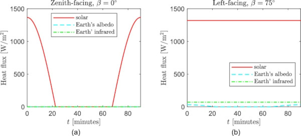
When considering a satellite operating in LEO, it is typical to consider as the worst-case scenario the one with the longest eclipse period and the greatest variation in solar radiation over time (Rickmann 2014; Galuppi and Royer-Carfagni 2025). This occurs when the solar rays align with the orbital plane, i.e., when the β angle shown in Fig. 4 is zero. In this scenario, the highest variability in heat fluxes is observed on the Zenith-facing surface. Conversely, when the β angle reaches its maximum value (β = ± 75°), the Sun's rays are nearly perpendicular to the orbital plane, resulting in longer exposure to solar radiation, particularly on the surface closest to the Sun (Left-facing, for β = 75°). This condition can be the most critical for absorbing materials like acrylic glass, as it corresponds to maximum heating. Figure 7 illustrates the radiation contributions (solar, albedo, and Earth's radiation) for these two scenarios, plotted over time, for a space station with a 90-min revolution period.
In (Galuppi and Royer-Carfagni 2025), a comprehensive thermal analysis was developed, accounting for the time variation of different heat sources, due to orbital motion, for windows of various orientations made either of fused silica and acrylic glass. This approach determines material temperatures while considering key parameters such as absorptivity, transmissivity, and reflectivity, accounting for their dependence on the radiation wavelength spectrum.
The temperature distribution is determined by solving the classical heat conduction equation, assuming the panel is uniformly heated on both its external and internal surfaces. Appropriate boundary conditions are applied to account for radiative heat exchange with the external space environment and convective flux with the interior environment of the station. Specifically, the radiative heat exchange at the panel surfaces is proportional to the difference between the fourth powers of the panel's absolute temperature and the environmental temperature. It is important to note that, while in terrestrial applications this condition can often be linearized due to the relatively small difference between surface and environmental temperatures, in space applications the full fourth-order boundary conditions must be retained, as linear approximations are not accurate. This leads to a highly non-linear problem. Another distinctive aspect of thermal problems in the space environment is that the temperature dependence of material properties, such as thermal conductivity and heat capacity, cannot be ignored due to the extreme temperature variations encountered.
As demonstrated by Galuppi and Royer-Carfagni (2025), the low thermal absorptivity of FS renders it largely unaffected by solar and albedo radiation, leading to lower temperatures and reduced sensitivity to the time-varying solar heating caused by orbital motion. Additionally, the thickness of the pane has a minimal impact in this case. In contrast, the high absorptivity of AG results in significantly higher temperatures, which rise with increasing thickness and exhibit a cyclical pattern aligned with the orbital period. For the first scenario β = 0, it was found that temperatures in AG windows cyclically vary with the orbital period, remaining within acceptable limits because the variability of the radiation is much faster than the time required by the pane to reach a steady state under a constant source. On the contrary, it was demonstrated that, for a longer heating, such as that experienced in the second scenario β = 75°, acrylic glass, 150 mm thick, can reach temperature exceeding 100 °C. Anyway, temperatures can be managed by scheduling the opening and closing times of the shutters or louvers, if present.
Besides FS and AG other materials, as listed in Table 2.2, are also worth considering. Notably, borosilicate glass, much less expensive than fused silica and easier to manufacture in large panes, possesses promising optical and thermal properties with significant potential for space applications that has yet to be fully explored and recognized. The use of coatings and the combination of panes made from different materials into a single unit is another important area of technological research, presently under consideration.
3.3 Optical properties
Transparency is a top priority for space station windows. While windows were traditionally designed as observation points for operational tasks such as operating robotic arms, inspections and controls, the rise of space tourism has transformed them into defining features. Each pane interacts with electromagnetic waves differently, reflecting, transmitting, and absorbing them based on material properties, thickness, and surface finishing. Optical transparency specifically refers to the transmissivity of visible light.
When a radiant energy Ei strikes a plate, part of the radiation, Er, is reflected, a part Ea is absorbed, and a part Et is transmitted. Reflectivity (ρ), absorptivity (α), and transmissivity (τ) coefficients depend on the wavelength λ, and are defined as.

Obviously,
![]()
The method proposed by Galuppi and Royer-Carfagni (2024) for evaluating the thermal properties of a pane in response to various radiation sources can also be applied to assess optical properties. This involves integrating the absorptivity, reflectivity, and transmissivity of the pane across the visible sunlight spectrum, for λ ∈ (380, 740) nm, indicated in Fig. 6a. In this range, fused silica panes exhibit almost zero absorptivity, a reflectivity of 6.8% and, consequently, an exceptionally high optical transparency of 93.2%. In contrast, the optical properties of acrylic glass are significantly influenced by the pane thickness. Figure 8 illustrates the coefficients of optical absorptivity, reflectivity, and transmissivity for acrylic glass as a function of pane thickness d across the range of 10–200 mm, calculated using material data from (Galuppi and Royer-Carfagni 2024).
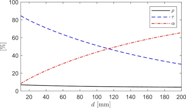
It is clear that thicker panes absorb more light, leading to reduced transparency. For a 150 mm thick acrylic glass, as considered in Sect. 3.1, an unexceptional optical transparency of around 39% is achieved. This observation is important, as the established experience is with fused silica, which absorbs minimal light and maintains visual clarity regardless of thickness: assuming the same conclusion for acrylic glass could lead to results below expectation. However, our results pertain to a specific type of acrylic glass. Other variants with superior properties may exist, but the absence of documented data in the literature, to the best of our knowledge, prevents a meaningful comparison.
4 Conclusions
Emerging trends in the space industry are driving the demand for larger, more efficient, and aesthetically pleasing windows for stations operating in low orbit, designed to provide a more immersive experience of viewing Earth and the cosmos. In this context, we have tackled the key challenges that arise in the design process. Specifically, the aim was to evidence that the technology employed in terrestrial applications cannot be directly applied to space. This is due to unique challenges posed by the harsh environmental conditions, implying material degradation, high mechanical loads, and time-varying radiation exposure. Consistently, the modeling shall be significantly more refined, necessitating specialized evaluations that are unnecessary in terrestrial design. Our focus was on materials like fused silica and acrylic glass, which are currently the most widely utilized.
Certainly, there are other materials worth considering for space applications, ranging from highly advanced options like aluminum oxynitride to more “humble” ones like borosilicate glass, which has yet to be utilized. In recent years, significant expertise has been gained in glazing for terrestrial applications, particularly in architecture, automotive, and shipbuilding. The new challenge may lie in leveraging this existing wealth of knowledge, such as techniques in glass lamination, and adapting it thoughtfully for space use. This approach could help reduce costs by building on established methods rather than starting ex novo.
Data availability
No datasets were generated or analysed during the current study.