This paper was first presented at GPD 2023.
Link to the full GPD 2023 conference book: https://www.gpd.fi/GPD2023_proceedings_book/

Authors:
- Miguel Ángel Núñez Díaz, ENAR
- Jesús M. Cerezo, ENAR
- Angel Mateo Marcos Núñez, ENAR
Abstract
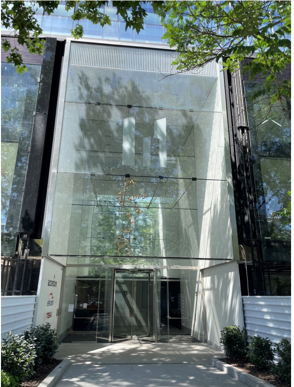
The project is a facade to access an office building. As an external image of the main access, we want to make a double skin of protection fully glazed.
The structural challenge consists in creating a double glass skin 9.00 m high and 6.50 m wide with the least number of elements to achieve the maximum transparency.
In order to eliminate elements, both skins must work together as a large beam supporting perpendicular stresses, for which stainless steel braces are arranged to join them.
The glasses are embedded laterally to support the vertical forces due to their own weight. With this solution, only a few small staples are seen in the entire glass panel, where the braces are collected, while the rest of the façade is totally transparent.
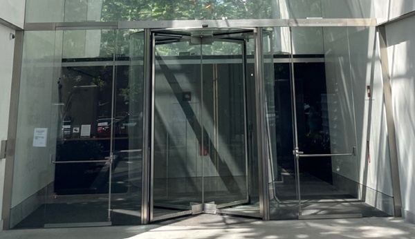
In the lower part of the façade, the access to the building is made through two pivot doors and a revolving door that are independent from the upper structural solution.
Introduction
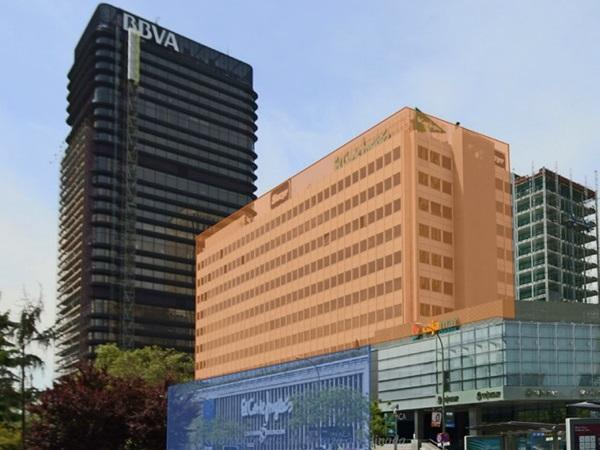
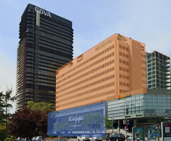
Nowadays in Madrid there are many buildings constructed in the 70’s with new façade systems for that age, but without a traditional construction. This means that the facades are a light construction with the best materials at that moment. Currently, these materials have an intense devaluation in many aspects, mainly aesthetically, but also since now there are many materials with better properties that can improve the behavior of the façade and achieve better energetic efficiency and sustainability. For this reason, many of these buildings are being refurbished, mainly with a new façade envelope.
This is our case, the building was constructed around 1975. The original construction is a rectangular building composed by two different volumes: the basement and the top building. The basement has a dimension of 32 x 89 m and 12 m height, and the top building inside the basement has a smaller dimension, 22 x 75 m, but it is higher, 35 m.
In the evolution of the life of the building, it was divided in two buildings and sold separately to two different properties, one for the basement and another one for the top building, but the access to the top building is obviously made through the basement building.
Both properties decided to make an integral refurbishment of their buildings, but with different architects (different projects) and at different time. The refurbishment of the top building was made first, including its own access, and finally, the basement was refurbished.
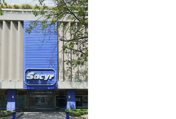
The top building is constructed with vertical steel mullions supporting a horizontal line of sandwich panels in the slab area, and a horizontal glass line in the window area. The basement building has a commercial use with an arcade in the bottom part with the glazed areas for the shops, and the façade on top of this was opaque with external concrete precast elements with a “S” shape of the total height.
The access to the top building is in the center of the façade without any signal in the opaque façade, only in the arcade between the big shop windows.
General Description
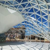
The intervention in the top building also requires the intervention in the bottom part to include an access to the new building, that is, a big representative access, not only a little access in the bottom floor. For that, the owner of the top building bought a space in the basement building over the access. With this acquisition the main idea was to make a big space for the lobby with the access and a big exterior façade to highlight the presence of the building in the street Paseo de la Castellana, which is one of the most important streets in Madrid. With this new space, architects generated a triple height space to configurate the main lobby in the building. To generate this space it was necessary to cut two slabs in all the area of the lobby.
This space has a double skin façade, the exterior face in the exterior line of the building to complete the exterior façade, and the interior face in the interior line of the window shops.
The exterior façade is an exterior-exterior façade while the interior façade is the enclosure of the lobby with the requirements of watertightness. In this interior face the access doors to the building were included.
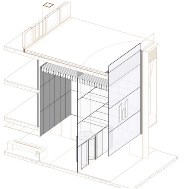
The main idea of the lobby façade is to get as much light as possible to introduce to the lobby, since the lobby has a low height and big depth from the exterior façade. For that, the façade needed to be as much transparent as possible without any frame elements that could decrease the amount of light from the exterior.
The interior façade has a height from the bottom to the top of 12 m, and a width of 7 m, having the doors a height of 3,00 m.
The exterior façade has the same dimension but without the inferior elements in the door position, this is: a width of 7 m and a height of 9 m, starting 3,00 m from the floor level. Both façades are separated 3,80 m.
The façades are composed by three horizontal glasses of 3,00 m high and 7,00 m wide, without vertical elements. Door access has been composed by a central revolving door, and two laterals pivoting doors as evacuation doors.
To increase the size of the lobby, due to its small dimensions, a mirror finishing was installed in the interior wall. This way, from the exterior view, the lobby has a bigger appearance than it is.
Structural scheme
To get the exterior transparent view without main structural elements it is necessary to think in the best way to support the façade. The façade configuration is mainly horizontal, so we considered supporting the glasses only in its lateral sides without other elements. The problem with this approach is the deformation, with a glass fixed side to side with 7,00 m of span, exposed to wind loads, we have a deformation of approximately 170 mm, and this deformation is not allowed for an exterior façade.
But if we can see the configuration of the total enclosure we have two parallel facades with the same configuration, and the question is, how we can use the two elements in order to improve the behavior against the wind loads.
The solution was to connect both façade and configure a system with a big depth in the direction of the wind loads, increasing the inertia of the system to decrease the deformation of the total façade. To connect the façade some perpendicular rods are installed in the joints of the glass. This scheme is easy to understand and takes advantage of the configuration of the façade.
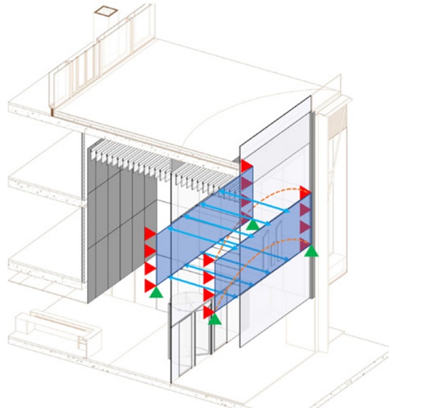
The weight of the glasses is supported in the lateral, directly over the main structure of the building, which was reinforced to support these loads. The weight of the rods are supported over the glasses.
All the connections are screwed, avoiding embedment elements that could induce extra effort or strain concentrations in the glass.
The inferior part of the doors is supported in the bottom, in the inferior slab, with different movements. For this reason it is necessary to create a vertical and horizontal joint between the glass facades and this door area.
In the bottom part a horizontal beam is situated to support the horizontal loads, and this is why in this area the perpendicular rods have not been installed, they are only installed in the intermediate glass joints.
Construction solution
The construction system must be as simple as the structural system, in order to get a strong solution, mainly in the conceptual way.
In this case to support the glasses in both sides, a vertical channel has been installed, fixing to a vertical steel tube supported directly in the main building structure. This channel is composed by two elements; one fixed “L” profile and an exterior removable cover, which fixes the glass. This element is designed in lacquered steel. In these points a watertightness membrane is installed in order to close the façade to the exterior.
Glasses are composed by three 10 mm thick ultraclear glass panes laminated with SGP, without holes or mechanically fixings. Glasses are fixed only in both sides with the exterior caps.
These fixing elements are blinded with the exterior finishings, giving the sensation that the glass is embedded in the lateral walls.
To connect both facades 4 perpendicular rods are situated in the intermediate glass joints. These elements are fixed to the glass with structural silicone glued to the glass. For this, glasses come with a stainless-steel plate fixed from the factory, and these plates are screwed to the rods on site with some tolerances to allow the fabrication. Rods have a diameter of 48 mm, and they have a connection that allows the rotation of the element to avoid the increase of strains in the glass face.
The weight of the rods is supported by the glass through the stainless steel plates to avoid permanent loads on the structural silicone. Joints between glasses are sealed.
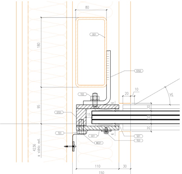
Rods are only installed in the intermediate glass joints, so it is necessary to have other elements to support the horizontal loads in the top and in the bottom part of the façade. In the top, the same system used in the lateral sides has been installed, with a steel profile fixed to the structure and an exterior cap to fix the glass.
In the bottom part, situated 3,00 m from the floor above the doors, a stainless steel beam is situated. This beam is composed by a plate 20 mm thick in “T” shape to minimize the height of the beam and increasing the depth to support the horizontal loads. The beam is supported in the lateral over the main structure. This plate is fixed with structural silicone to the façade glass to avoid its vertical deflection.
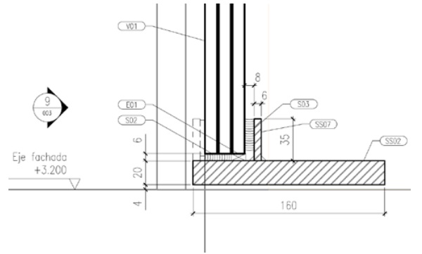
In the interior façade doors are situated below the glass façade. All this area is supported on the bottom slab, and for this it is necessary to have a joint that allows the movements between the two different systems. This joint is situated in the bottom beam of the façade.
In the middle of the façade a revolving door is situated. This door is composed by curved glasses and its roof is also made in glass. In the lateral of this door the two pivoting doors are situated. Doors have a horizontal top and bottom stainless steel profile to insert the pivots and lockers needed. These profiles are coordinated with the horizontal beam at the top.
Conclusions
The main conclusion we can obtain is that the most important issue to design an element is to have clear the structural behavior of the elements to get a simple solution.
As secondary conclusions we obtain the following:
- It is possible to use the glass facades to support the wind loads without main structures.
- Constructive system and structural system must be thought at the same time to get the best and optimal solution.
- It is necessary to have clear the deformation and displacements of the elements in order to combine the joints and allow the different movements.
Acknowledgements
MERLIN PROPERTIES. Owner.
ORTIZ.LEON. Architect Office.
BOVIS. Project Manager.
INASUS. Façade Contractor


 demonstrator at Glass Technology Live during Glasstec 2024 (© Cas Maertens).")