Article Information
- Digital Object Identifier (DOI): 10.47982/cgc.8.397
- This article is part of the Challenging Glass Conference Proceedings, Volume 8, 2022, Belis, Bos & Louter (Eds.)
- Published by Challenging Glass, on behalf of the author(s), at Stichting OpenAccess Platforms
- This article is licensed under a Creative Commons Attribution 4.0 International License (CC BY 4.0)
- Copyright © 2022 with the author(s)
Authors:
- Zhikang Deng - ETH Zurich, Institute of Structural Engineering
- Vlad-Alexandru Silvestru - ETH Zurich, Institute of Structural Engineering
- Julien Michels - re-fer AG
- Lingzhen Li - ETH Zurich, Institute of Structural Engineering / EMPA Structural Engineering Research Laboratory
- Elyas Ghafoori - ETH Zurich, Institute of Structural Engineering / EMPA Structural Engineering Research Laboratory
- Andreas Taras - ETH Zurich, Institute of Structural Engineering
Abstract
Previous research has shown that glass beams with external, mechanical post-tensioning along their edges show better structural performance than glass beams without any such reinforcement. The initial and post-fracture load-bearing capacity of glass beams can be increased by reinforcing them with stainless steel or fiber-reinforced plastic (FRP) tendons that are post-tensioned and connected to the beam edges. However, post-tensioning of stainless steel or FRP bars or strips is complex and challenging because it often requires special setups, such as hydraulic jacks.
Iron-based shape memory alloys (Fe-SMAs) are promising post-tensioning materials due to their efficient activation procedure and good mechanical properties. The target prestress level can be introduced by heating the Fe-SMA to a specific temperature followed by cooling down naturally to ambient temperature. As a contribution to assessing the feasibility of strengthening glass elements with adhesively bonded Fe-SMA strips, this paper focuses on the bond behavior of glass-to-Fe-SMA lap-shear joints based on numerical investigations. A finite element model is developed to evaluate the effect of adhesive thickness, Fe-SMA strip thickness and bond length on the structural behavior of glass to Fe-SMA lap-shear joints.
1. Introduction
Over the past decades, glass has been increasingly applied for structural elements, such as beams and fins. Using glass structurally is challenging due to the lack of possibilities to redistribute stress concentrations, leading to brittle failure modes. To fulfil safety requirements, special attention needs to be given to the fracture state and the post-fracture state when designing with glass. In most cases, laminated safety glass is used to address these challenges. However, the load-carrying capacity of laminated glass after initial glass breakage is significantly lower than its load-carrying capacity in an intact state and leads to design provisions that account for a fundamentally brittle failure mode, with no stress redistributions and structural ductility.
Over the past years, several concepts for post-tensioned glass beams were developed to improve the performance of glass beams, both before and after glass failure. Stainless steel (e.g. Firmo et al. 2020) and fiber-reinforced plastic (FRP) (e.g. Bedon and Louter 2016) were used as reinforcement or post-tensioning elements for glass beams, often connected to the beam edges. However, the pre-stressing methods of stainless steel and FRP are usually laborious, often require special facilities, such as hydraulic jacks, for stress application and therefore entail a complex and space-consuming detailing at the member ends. Iron-based shape memory alloys (Fe-SMAs) are promising post-tensioning materials due to their efficient and rather simple activation procedure.
The required prestress level can be achieved by heating the pre-strained Fe-SMA to a specific target temperature followed by cooling down naturally to ambient temperature. For instance, an approximate pre-stress of 360 MPa can be obtained with an activation temperatureof 160 °C (Wang et al. 2021). The successful application of Fe-SMAs for strengthening concrete and steel structures (e.g. Izadi et al. 2018) as well as its efficiency and rather low cost (Hosseini et al. 2019)indicate that the Fe-SMA might be a promising candidate for strengthening structural glass elements.
However, the mechanical end anchorage currently used for Fe-SMA strengthening systems (Hosseini et al. 2019) would lead to stress concentrations in glass elements. An experimental study, which shows much potential of adhesive bonding in Fe-SMA strengthening systems, was conducted recently by the authors. Therefore, adhesive bonding is considered a more appealing solution for realizing the end anchorage of the Fe-SMA tendons on glass elements.
Adhesives, usually, are the weakest and most critical components in adhesively bonded systems. Hence, adhesives with proper behavior for bonding Fe-SMA to glass need to be identified first. Although various studies exist about the behavior of different adhesives in glass-steel (e.g. Cupac et al. 2021) and glass-FRP (e.g. Cagnacci et al. 2021) joints and the gained knowledge might be applicable,glass-to-Fe-SMA joints need to be investigated as well to assess their bond strength and performance.Adhesive strength and failure analyses are complicated tasks because of the complex material properties and bonding behavior. The finite element (FE) method based on continuum mechanics approaches is a typical method to analyze the performance of adhesive joints.
However, these methods are sensitive to the element size (Feih et al. 2005). Cohesive zone models (CZM) have been widely used over the last few years with their advantages of modeling the entire debonding process(crack initiation and propagation) and of being insensitive to the mesh size. Traction-separation laws are typically used to characterize the debonding of the substrates in CZM. Damage initiation criteria can be defined for the cohesive zone element depending on the loading condition of the adhesive. The crack growth is governed by the energy release rate (GI, GII, and GIII).
In this contribution, the cohesive zone model was used to simulate the behavior of adhesives. A finite element model was developed to evaluate the effect of adhesive thickness, Fe-SMA strip thickness and bond length on the structural behavior of glass-to-Fe-SMA lap-shear joints. The influence of high temperature (results from activating the Fe-SMA) on the mechanical behavior of the lap-s hear joints was investigated experimentally in our other contribution (Silvestru et al. 2022), which will not be included in this work.
2. Material properties and model assumptions
The main objective of this contribution is to propose a finite element model, including suitable assumptions for the involved materials, that allows investigating the bonding behavior of the glass-to-Fe-SMA lap-shear joints. For this, the material properties of glass, Fe-SMA and adhesive should be defined properly. This section introduces the methods to determine the material properties of the Fe-SMA and the adhesives.
2.1. Material properties determination for the Fe-SMA
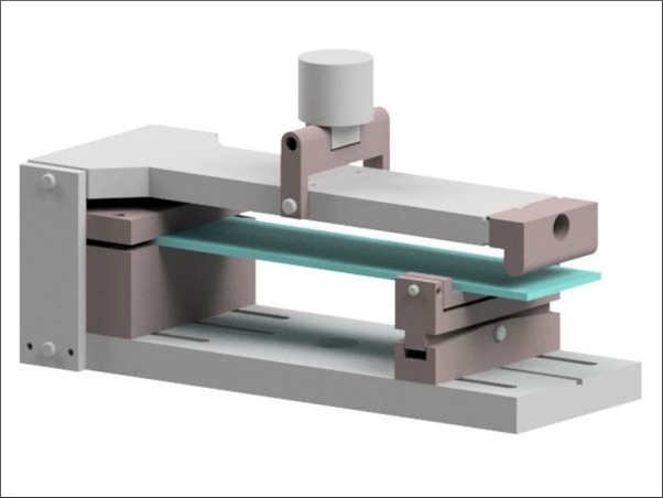
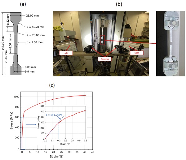
The Young’s modulus and the true stress-true strain relationship of the Fe-SMA were defined in the FE model to simulate the elastic-plastic behavior of Fe-SMA. Uniaxial tensile tests were carried out to obtain the Young’s modulus and nominal stress-nominal strain relationship of the pre-strained Fe-SMA. The tests were performed displacement-controlled with a speed of 0.012 mm/s on a Zwick universal testing machine. The used test specimen geometry is shown in Fig. 1a, while the test setup is illustrated in Fig. 1b.
A digital image correlation (DIC) system was used to measure the deformations of the specimen during the test. Based on the photos taken with two cameras during testing, post-processing with the software VIC-3D 9 from Correlated Solutions, Inc. allows evaluating occurring displacements between selected points on the specimen surface as well as strain fields. The true stress and strain were calculated based on the obtained nominal stress and nominal strain with equations (1) and (2):
In equations (1) and (2), σtrue and εtrue are the true stress and true strain, respectively. σnom and εnom are the nominal stress and nominal strain, respectively. For the studied case, the plastic strain is calculated by the equation (3):
![]()
In equation (3), εpl is the plastic strain and E is the Young’s modulus. Four specimens were tested and the test results exhibited almost no variations according to the load-displacement curves. The results of one of the tests were further analyzed in the software VIC-3D 9 to determine the strain values, which were required for the simulation of the Fe-SMA. A subset of 25 and a step size of 8 were used in the post-processing of the results from the DIC measurements.
2.2. Material properties determination for the adhesives
The CZM is used to simulate the behavior of the adhesive. The interface stiffness (Knn and Kss in opening and shear direction, respectively), the separation strength (tn,0 and ts,0 in tension and shear direction, respectively) and the energy release rate (GI and GII in opening and shear direction, respectively) need to be defined in the CZM. The interface stiffness is used to describe the stress-separation relationship of the adhesive before adhesive damage. The separation strength and the energy release rate govern the crack initiation and propagation, respectively. An approximate value can be given to the interface stiffness if no experimental data are available. Some practical estimations are Knn = E and Kss = G (Campilho et al. 2012), or Knn = E / tadhesive and Kss = G / tadhesive (Xu and Wei 2013). However, these estimations are only valid when the adhesive is thin.
One other option is obtaining the cohesive parameters with the inverse method (Banea et al. 2011), which consists of an iterative curve fitting procedure to reduce the error between experimental results and the FE simulation. To the best of the authors' knowledge, for the specific adhesives (SikaPower-1277, Araldite 2047-1 and 3M DP490) with finite thickness, there is no available data about the interface stiffness. Hence, the inverse method was used to determine the interface stiffness. It was based on the FE model described in section 2.3 and the lap-shear tests described in this section. The material properties, except the interface stiffness, used to define the CZM are listed in Table 1.
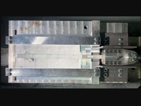
Two epoxies (SikaPower-1277 and 3M DP490) and one methacrylate (Araldite 2047-1) were selectedfor structurally bonding Fe-SMA to glass. While SikaPower-1277 was previously investigated to bond Fe-SMA to steel (Wang et al. 2021), the other two adhesives exhibited a good performance for bonding glass to anodized aluminum (Belis et al. 2011). Considering the different thermal expansion coefficient of glass, Fe-SMA and adhesive, adhesives with a thickness of 0.5 mm and 1.5 mm were considered firstly. To obtain the interface stiffness, the FE simulation results were compared with the lap shear test results. The used test setup and the specimen dimensions are shown in Fig. 2.
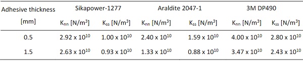
Details on the experimental investigations and the obtained results can be found in Silvestru et al. (2022) and are not within the scope of this contribution. A total of 18 specimens were tested for the three adhesives, including two different joint thicknesses per adhesive as shown in Table 2. The experimental results (see load vs. displacement curves in Fig. 3) were compared with the results of the FE models (described in section 2.3). The assumptions for the interface stiffness are Knn = α x E and Kss = α x G. The value of α was used as a calibration factor and determined to obtain an acceptable level of agreement between the experimental results and the FE simulation results according to the iterative curve fitting procedure. The determined interface stiffness values are shown in Table 3, while the load vs. displacement curves obtained from the simulations are plotted in Fig. 3 together with the experimental results.
Table 1: Material properties of the adhesives used as input data for the simulations
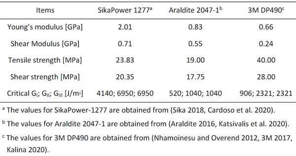
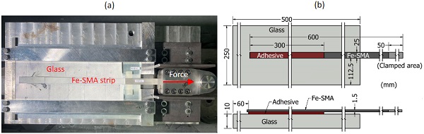
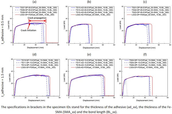
Table 2: Adhesive types and dimensions for the specimens investigated in lap-shear tests
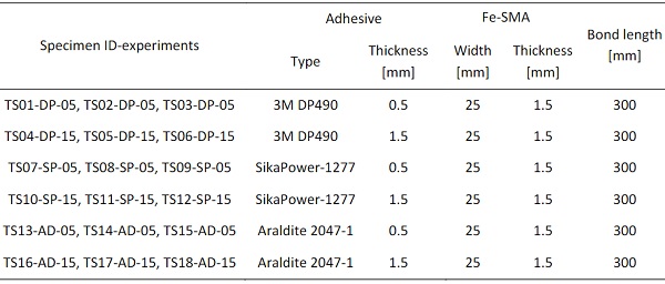
Table 3: Determined interface stiffness values for joints with finite adhesive thickness
2.3. Finite element model
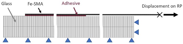
A 2D finite element model was developed in the commercial finite element software ABAQUS 2021. The glass bottom and right end surfaces were fixed in vertical and horizontal directions as the boundary condition. A reference point was created and connected to the right end of the Fe-SMA by coupling. A displacement of 140 mm (large enough to ensure that the specimen was loaded to failure) was applied to the reference point. The reaction force and translation of the reference point were extracted to characterize the performance of the lap-shear joints.
A general mesh size of 1 mm was used in thelongitudinal direction of the glass panel, the adhesive and the Fe-SMA strip. In the thickness direction, one element was assigned to the adhesive and two elements were assigned to the Fe-SMA strip and the glass panel. The mesh and the boundary conditions are shown in Fig. 4. The element type for the glass panel and the Fe-SMA strip is CPS4I (4-node bilinear plane stress quadrilateral, incompatible modes). 4-node two-dimensional cohesive elements (COH2D4) were used to simulate the adhesive bonding behavior. A quasi-static analysis was performed for the 2D models.
For glass, a linear-elastic material behavior was assumed in the simulations, with a Young’s modulus of 70 GPa and a Poisson’s ratio of 0.23 (Haldimann et al. 2008). No failure criterion was considered in
the simulations for glass, since the focus was set on the adhesive failure, which was dominant in the lap-shear tests. The stress in the glass from the simulation was compared with the inherent strength of 45 MPa (Haldimann et al. 2008) to check if glass failure could have occurred previous to the adhesive failure.
An elastic-p lastic constitutive relationship was used in the simulations for the Fe-SMA. The stress-strain relationship is obtained from the uniaxial tensile test discussed in section 2.1. The Young’s modulus is 151.7 GPa which is determined from the nominal stress-strain relationship before Fe-SMA reaching 0.2% strain. The Poisson’s ratio is assumed 0.3 (Fritsch et al. 2019). Thirty-four true stress-true strain data points after 0.2% strain till the maximum strain were selected to characterize the elastic-plastic behavior of the Fe-SMA. Because no Fe-SMA failure occurred during the lap-shear tests, no failure criterion for Fe-SMA was defined. When the Fe-SMA thickness was assumed very thin (0.5 mm), the stress and strain of the Fe-SMA from the simulation were compared with the values from the uniaxial tensile test to check if Fe-SMA failure could have occurred previous to adhesive failure.
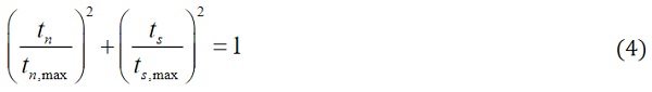
The CZM was used to simulate the behavior of the adhesive. The triangular traction-separation response (Campilho et al. 2011) was assumed. The quadratic stress criterion in equation (4) was used to govern the crack initiation. In equation (4), tn and ts are the normal and shear contact stress, respectively. tn,max and ts,max are the corresponding peak values. The damage initiates and the reduction of stiffness begins when equation (4) is fulfilled. Benzeggagh-Kenane (BK) form fracture criterion was used to control the crack propagation, which is based on the dissipated fracture energy.
To validate the ability of the proposed FE model to simulate the lap shear joints, the proposed model was used to simulate the steel-to-Fe-SMA lap shear joints investigated experimentally by Wang et al. (2021). The tests on steel-to-Fe-SMA lap-shear joints were carried out on the same setup described in section 2.2. The adhesive Sikapower-1277 was used with thicknesses of 0.35 mm and 0.45 mm. The interface stiffness defined for simulating the steel-to-Fe-SMA lap-shear joints was assumed with the same value as given for SikaPower-1 277 with a thickness of 0.5 mm in Table 3. The other parameters necessary for the CZM were defined according to Table 1. The maximum load obtained from the FE simulation is 61 kN and is in an acceptable agreement with the experimentally obtained value of 57 kN.
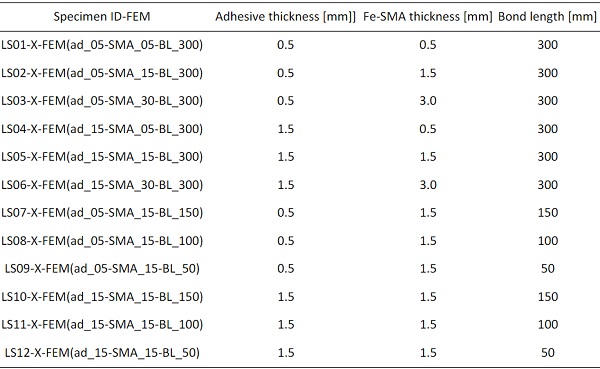
To investigate the effects of the adhesive thickness, Fe-SMA thickness and bonding length on the structural behavior of the glass-to-Fe-SMA lap-shear joints, based on the dimension of the lap-shear test specimens shown in Fig. 2b, two adhesive thicknesses (0.5 mm and 1.5 mm), three Fe-SMA thicknesses (0.5 mm, 1.5 mm and 3 mm), and four bonding lengths (50 mm, 100 mm, 150 mm and 300 mm) were considered in the simulations. The different specimens considered in the FE simulation with their varied dimensions are listed in Table 4. X in specimen ID-FEM represents AD, DP, or SP, indicatingthe specimen bonded with Araldite 2047-1, 3M DP490 or SikaPower-1277, respectively.
Table 4: Parameter matrix for the finite element simulations
3. Results and discussion
3.1. The effect of adhesive thickness
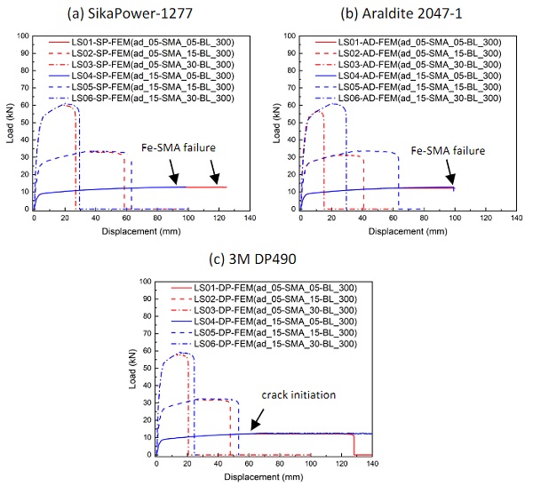
The adhesive thickness is one of the main factors influencing the structural behavior of steel-steel, aluminum-aluminum, and FRP-FRP joints (Shah and Tarfaoui 2016). Two different adhesive thicknesses (0.5 mm and 1.5 mm) were considered and their influence on the load-carrying capacity of the joint and the maximum displacement at the loaded end of the strip were evaluated. The obtained load vs. displacement curves are shown in Fig. 5.
For the specimens with 0.5 mm thick Fe-SMA strips, increasing the adhesive thickness does not make a significant difference in the results. There is a high probability of Fe-SMA failure because of the lower load-carrying capacity. When 1.5 mm and 3.0 mm thick Fe-SMA strips are considered, increasing the adhesive thickness slightly increases the load-carrying capacity and the maximum displacement. The reason for this is that the thicker adhesive joints allow for more shear displacement. The increase of load-carrying capacity and displacement with increased adhesive thickness is more pronounced for the specimens with Araldite 2047-1. This is because Araldite 2047-1 is more ductile than the other two adhesives; thus, more shear displacement is possible together with the longer effective bond length that this adhesive is exhibiting.
3.2. The effect of Fe-SMA thickness
The current production line for Fe-SMA strips in re-fer AG is designed for Fe-SMA strips with the thickness of 1.5 mm (re-fer AG 2022). However, in the future this might be extended to other thicknesses, if new applications will show a high enough demand. Three Fe-SMA thicknesses (0.5 mm, 1.5 mm and 3.0 mm) were considered in this contribution. The influence of the Fe-SMA thickness on the load-carrying capacity and the maximum displacement at the loaded end of the Fe-SMA strip was evaluated and compared as shown by the load vs. displacement diagrams in Fig. 5.
The load-carrying capacity is increasing with higher Fe-SMA thickness; however, the maximum displacement is decreasing. The stress in thicker Fe-SMA strips is lower than in thinner ones for the same load, resulting also in significantly lower strains and implicitly in smaller total displacements. At the same time, with increasing thickness of the Fe-SMA strip also its stiffness is increased. When the Fe-SMA adherent gets stiffer and therefore deforms less, the stress peaks at the loaded bond end of the adhesive joint are lower and higher stresses can be reached in the adhesive over a longer area of the bond length.
This results in a higher load-carrying capacity, as shown by the results in Fig. 5. However, one should consider that by further increasing the Fe-SMA thickness, the increasing peel stresses resulting from the eccentric alignment of the two adherents will limit the load-carrying capacity of such single lap-shear joints. For a thin Fe-SMA thickness of 0.5 mm, the load-carrying capacity can be limited by Fe-SMA failure instead of adhesive failure, as shown by the simulations with SikaPower-1277 and Araldite 2047-1.
3.3. The effect of bond length
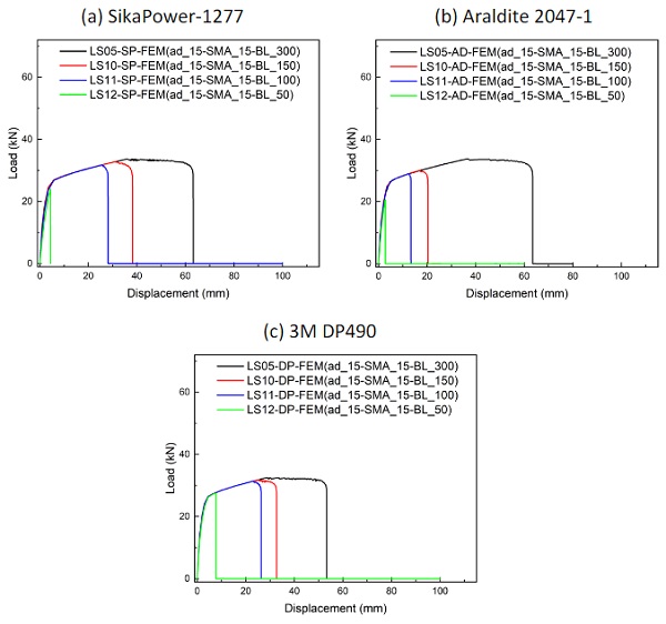
During activation, the Fe-SMA is heated up to high temperatures of at least around 160°C. Since the adhesive will reach similarly high temperatures, it might be damaged. Hence enough effective bond length during and after activation should be guaranteed as anchorage length. Four bond lengths (50 mm, 100 mm, 150 mm and 300 mm) were considered for specimens with 1.5 mm thick adhesivejoints. The results are shown and compared as load vs. displacement curves in Fig. 6. The maximum reached loads and especially the total displacements are rather low when the bond length is 50 mm.
The load-carrying capacity and the maximum displacement increase obviously for all three adhesives as the bond length is increased from 50 mm to 100 mm. However, the load-carrying capacity only increases slightly when the bond length is increased above 100 mm, especially for 3M DP490. This is because 3M DP490 and also Sikapower-1277 are on the one hand more brittle than Araldite 2047-1. On the other hand, the related different effective bond lengths might be a reason for this.
4. Conclusion
A finite element model was developed in this contribution with the aim of studying the effect of adhesive thickness, Fe-SMA strip thickness and bond length on the structural behavior of glass-to-Fe-SMA lap-shear joints with different adhesives. The models were validated using steel-to-Fe-SMA lap-shear tests as reference; the FEM-simulations thus served the purpose of deepening the understanding of the test results and expanding the range of studied parameters. The following conclusions can be drawn based on the simulation results:
- Thicker adhesives lead to a higher load-carrying capacity and larger total displacements. The reason for this is that the thicker adhesive allows for more shear displacement and as a consequence a longer bonding length can be activated. The increase of load-carrying capacity and displacement with increased adhesive thickness is more pronounced for specimens with the studied adhesive of type Araldite 2047-1.
- The load-carrying capacity is increasing with higher Fe-SMA thickness.
- The load-carrying capacity and especially the total displacement increase significantly as the bond length is increased from 50 mm to 100 mm, especially for the brittle adhesives. However, for such adhesives, the load-carrying capacity does not increase to the same amount when the bond length is increased over 100 mm. For the more ductile adhesive, an increase of the load-carrying capacity and the total displacement can be achieved also by increasing the bond length above 100 mm.
Acknowledgements
This research was financially supported by Innosuisse through the innovation cheque application number 51447.1 INNO-ENG.
References
Bonding composite parts to multiple materials-3M™scotch-weld™ structural adhesives (2017). https://multimedia.3m.com/mws/media/1559358O/3m-composite-bonding-benelux-low-res.pdf
Araldite-2047-1 data sheet (2016). https://www.intertronics.co.uk/wp-content/uploads/2016/01/Araldite-2047-1.pdf
Banea, M. D., da Silva, L. F. M., Campilho, R. D. S. G.: Mode I fracture toughness of adhesively bonded joints as a function of temperature: Experimental and numerical study. Int J Adhes Adhes. 31, 273-279 (2011). https://doi.org/10.1016/j.ijadhadh.2010.09.005
Bedon, C., Louter, C.: Finite-element numerical simulation of the bending performance of post-tensioned structural glass beams with adhesively bonded cfrp tendons. Am. J. Appl. Sci. 9, 680-691 (2016). https://doi.org/10.3844/ajeassp.2016.680.691
Belis, J., Van Hulle, A., Out, B., Bos, F., Callewaert, D., Poulis, H. J. P. o. G. P. D.: Broad screening of adhesives for glass-metal bonds. 12th International Conference on Architectural and Automotive Glass.286-289 (2011).
Cagnacci, E., Orlando, M., Salvatori, L., Spinelli, P.: Four-point bending tests on laminated glass beams reinforced with FRP bars adhesively bonded to the glass. Glass Struct Eng. 6, 211-232 (2021). https://doi.org/10.1007/s40940-021-00147-9
Campilho, R. D. S. G., Banea, M. D., Pinto, A. M. G., da Silva, L. F. M., de Jesus, A. M. P.: Strength prediction of single- and double-lap joints by standard and extended finite element modelling. Int J Adhes Adhes. 31, 363-372 (2011). https://doi.org/10.1016/j.ijadhadh.2010.09.008
Campilho, R. D. S. G., Pinto, A. M. G., Banea, M. D., da Silva, L. F. M.: Optimization study of hybrid spot-welded/bonded single-lap joints. Int J Adhes Adhes. 37, 86-95 (2012). https://doi.org/10.1016/j.ijadhadh.2012.01.018
Cardoso, M. G., Pinto, J. E. C., Campilho, R. D. S. G., Nóvoa, P. J. R. O., Silva, F. J. G., Ramalho, L. D. C.: A new structural two-component epoxy adhesive: Strength and fracture characterization. Procedia Manuf. 51, 771-778 (2020). https://doi.org/10.1016/j.promfg.2020.10.108
Cupac, J., Louter, C., Nussbaumer, A.: Post-tensioning of glass beams: Analytical determination of the allowable pre-load. Glass Struct Eng. 6, 233-248 (2021). https://doi.org/10.1007/s40940-021-00150-0
Feih, S., Shercliff, H. J. I. J. o. A., Adhesives. Adhesive and composite failure prediction of single-L joint structures under tensile loading. Int J Adhes Adhes. 25, 47-59 (2005). https://doi.org/10.1016/j.ijadhadh.2004.02.005
Firmo, F., Jordao, S., Neves, L. C., Bedon, C.: Exploratory study on simple hybrid or pre-stressed steel-glass I-beams under short-term bending - Part 1: Experiments. Compos Struct. 234, (2020). https://doi.org/10.1016/j.compstruct.2019.111651
Fritsch, E., Izadi, M., Ghafoori, E.: Development of nail-anchor strengthening system with iron-based shape memory alloy (Fe-SMA) strips. Constr Build Mater. 229, (2019). https://doi.org/10.1016/j.conbuildmat.2019.117042
Haldimann, M., Luible, A., Overend, M.: Structural use of glass.10, (2008). https://doi.org/10.2749/sed010
Hosseini, A., Michels, J., Izadi, M., Ghafoori, E.: A comparative study between Fe-SMA and CFRP reinforcements for prestressed strengthening of metallic structures. Constr Build Mater. 226, 976-992 (2019). https://doi.org/10.1016/j.conbuildmat.2019.07.169
Izadi, M. R., Ghafoori, E., Shahverdi, M., Motavalli, M., Maalek, S.: Development of an iron-based shape memory alloy (Fe-SMA) strengthening system for steel plates. Eng. Struct. 174, 433-446 (2018). https://doi.org/10.1016/j.engstruct.2018.07.073
Kalina, T.: Determination of cohesive parameters for mode II of epoxy adhesive. Manuf. Technol. 20, 190-194 (2020). https://doi.org/10.21062/mft.2020.042
Katsivalis, I., Thomsen, O. T., Feih, S., Achintha, M.: Development of cohesive zone models for the prediction of damage and failure of glass/steel adhesive joints. Int J Adhes Adhes. 97, (2020). https://doi.org/10.1016/j.ijadhadh.2019.102479
Nhamoinesu, S., Overend, M.: The mechanical performance of adhesives for a steel-glass composite façade system. Challenging glass 3.293-306 (2012).
re-fer AG. https://www.re-fer.eu/en/re-plate-2/re-plate/. Accessed 10 February 2022
Shah, O. R., Tarfaoui, M.: Effect of adhesive thickness on the Mode I and II strain energy release rates. Comparative study between different approaches for the calculation of Mode I & II SERR's. Compos Part B-Eng. 96, 354-363 (2016). https://doi.org/10.1016/j.compositesb.2016.04.042
Shahverdi, M., Michels, J., Czaderski, C., Motavalli, M. J. C., Materials, B.: Iron-based shape memory alloy strips for strengthening RC members: Material behavior and characterization. Constr Build Mater. 173, 586-599 (2018). https://doi.org/10.1016/j.conbuildmat.2018.04.057
SikaPower-1277 Product data sheet (2018). https://industry.sika.com/content/dam/dms/gb01/7/sikapower_-1277.pdf
Silvestru, V. A., Deng, Z., Michels, J., Li, L., Ghafoori, E., Taras, A.: Application of an iron-based shape memory alloy for post-tensioning glass elements. Submitted to Glass Struct. Eng. (2022).
Wang, W., Hosseini, A., Ghafoori, E.: Experimental study on Fe-SMA-to-steel adhesively bonded interfaces using DIC. Eng. Fract. Mech. 244, (2021). https://doi.org/10.1016/j.engfracmech.2021.107553
Xu, W., Wei, Y.: Influence of adhesive thickness on local interface fracture and overall strength of metallic adhesive bonding structures. Int J Adhes Adhes. 40, 158-167 (2013). https://doi.org/10.1016/j.ijadhadh.2012.07.012


 demonstrator at Glass Technology Live during Glasstec 2024 (© Cas Maertens).")