Authors: Johan Sjöström, Marcin Kozłowski, Daniel Honfi, David Lange, Joakim Albrektsson, Peter Lenk and Jerry Eriksson
Source: International Journal of Structural Glass and Advanced Materials Research, 4(1), 24-40. Science Publications
DOI: https://doi.org/10.3844/sgamrsp.2020.24.40
Abstract
Glass structures have been increasingly utilised in modern construction for decades with load-bearing walls or facades as the most common elements. However, the use of glass beams has recently been given more attention but its application as load-bearing elements has been limited by the low tensile resistance, its brittle behaviour during failure and concerns of its performance in case of fire. Parts of these aspects can be covered by using Timber-Glass composites beams, with timber flanges and a glass web. Previous research and practical application show high potential for this type of composites in ambient temperatures but its performance in fire has not yet been assessed and thus not completely understood. This study describes what to our knowledge is the first full scale fire resistance tests of Timber-Glass composites beams. These tests results are also analysed using finite-element simulations in order to understand the mechanisms of failure during the tests. It was shown that adding a timber flange to a glass web can have severe complications for the fire resistance, however, there are many possible ways to circumvent these issues.
Introduction
Background and Motivation
The use of glass in structural applications has increased significantly in the last decades. The examples of architectural assemblies where glass is part of the loadbearing system is tremendous and shows great variability.
While first solutions for load-bearing glass elements, e.g., beams, involved only glass panes laminated together with a polymeric interlayer, modern designs combine glass with other structural materials. This forms hybrids and composites to overcome undesired failure characteristics of glass such as inherent brittleness, much lower tensile than compressive strength, risk of fracture due to practically unavoidable defects and decrease of strength with time (Haldimann et al., 2008).
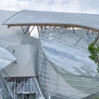
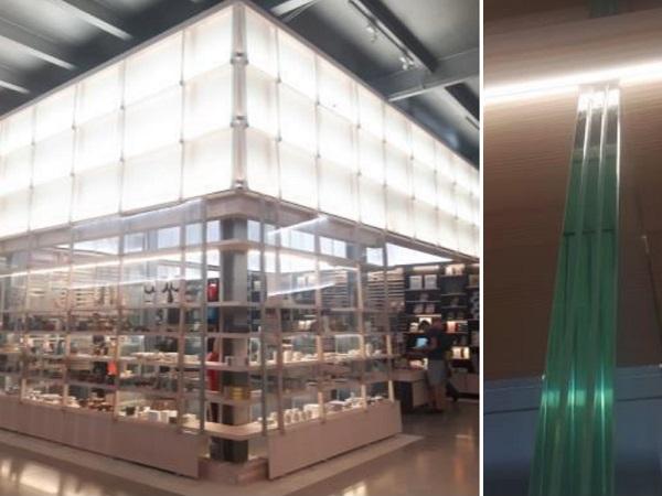
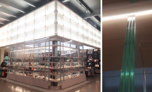
The principle of combining glass with other materials is to provide post-breakage strength and ductility thus enhancing post-breakage performance and the overall robustness of the design by using ductile materials in the cross-section, where the tensile stress is at its maximum (Martens et al., 2015). Although structurally not as efficient as e.g. steel reinforcement (Louter et al., 2012), an aesthetically pleasant solution, which is also beneficial for the wellbeing of building occupants and sustainable concerning its overall environmental impact, is the combination of glass with wood. An interesting example is the pavilion of the V&A shop in London, with glass fins, timber shelfs and timber brackets holding up thin glass shingles (Fig. 1).
Structural glass detailing was originally inspired by timber detailing. Both industries are demanding high level of craftsman shift with key attention to understanding connection behaviour. Capacity of connections are determining structural sizes of elements. Combination of rigid glass component and softer timber elements has a positive benefit on reducing peak glass stress concentrations which was understood long time ago. Both materials are natural and are symbiotic to each other which is very popular with designers especially if sustainable but contemporary alternative scheme are requested.
Besides using timber and load-bearing glass in hybrid structural systems, it is also possible to construct composite structural elements, where the two materials are bound together to form a common load-bearing mechanism as a single unit. One example of this idea is a recently developed concept, in which timber flanges are bonded to glass webs creating timber-glass composite (TGC) beams with improved load-bearing structural behaviour in intact state but also after initial glass failure (Kozłowski et al., 2014; Kozłowski, 2014; Kozłowski et al., 2015; Dorn et al., 2014; Furtak and Rodacki, 2018). In general, the concept of TGC beam involves a transparent web made of glass (primarily annealed (AN) float glass) and timber flanges bonded together with an adhesive. Under loading the stress in the glass web increases until it reaches the tensile strength of glass resulting in brittle failure of the individual glass sheets, however, it does not lead to the total failure of the composite beam.
Even if the glass web fractures, the glass shards are held in place by (1) the polymer interlayer which transfers load to adjacent sheets in the laminated glass web and (2) the adhesive and the timber flanges; thus the beam can still withstand sustained loading. Similar to the functioning of laminated glass alone (Louter et al., 2012), the timber flange (working in tension) with the bond line adhesive connection acts as a bridge: The forces that before failure were carried by the tensile zone of the web, are transferred to the timber flange after glass lamella failure. Moreover, timber top flange protects the slender web from lateral torsional buckling. The similar principle was applied for wall panels, in which a glass pane is bonded to a timber frame (Ber et al., 2014; Kozłowski et al., 2015; Nicklisch et al., 2015).
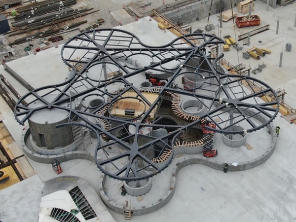
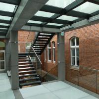
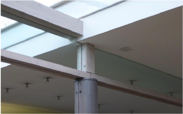
The concept of TGC elements has also been applied in practice, although only occasionally so far. A prominent example of a TGC girder is shown in Fig. 2 from the Palafitte Hotel, more details about the structure are given in (Kreher and Natterer, 2004).
The structural behaviour of TGC beams has been extensively investigated under static loads by experimental and numerical methods at ambient temperature of approximately 21±2°C. However, the loadbearing elements installed in buildings should retain their integrity and load-bearing capacity also at elevated temperatures and under fire conditions (Bedon and Louter, 2018; Honfi et al., 2018; Kozłowski et al., 2018a). This is particularly important for multi-story buildings where small scale TGC applications for windows are already applied by building industry (Scleicher, 2016). Since the structural performance of adhesives as well as the stiffness and strength properties of the interlayers used in laminated glass are sensitive to high temperatures, the concept needs to be verified in fire conditions in order to facilitate broader practical application. Furthermore, glass is susceptible to temperature gradients and the combined effect of thermal and mechanical strains in glass may lead to pre-mature fracture of the material and the verification of the safety against such temperature related phenomena is not straightforward.
The aim of the authors was to understand fire performance of TGC components and look at possible design improvements to provide at least 30 min fire resistance. Accomplishing this goal will enable to spread this exciting product into more projects.
Previous Research
First extensive theoretical analysis of thermal cracking of glass was reported by Keski-Rahkonen (1998). The author investigated thermal breakage of a monolithic annealed soda-lime glass pane partially shaded (at edges) by a frame and concluded that a temperature difference ΔT of about 80°C between the heated surface glass temperature and the edge temperature is needed to initiate cracking. Pagni and Joshi (1991) considered a similar problem and approximated ΔT as 58°C, the difference in the value of ΔT was caused by the assumption of different values of the tensile strength, Young’s modulus and linear thermal expansion coefficient of glass. However, these temperature differences depend on the width of the shaded area and, to some degree, also on the thickness of the glass pane.
A relatively large number of experimental studies related to the resistance and thermal performance of glass have been focused on thermal breakage (Mognato and Barbieri, 2013; Malou et al., 2013; Wang et al., 2013; Karlsson, 2017; Vandebroek, 2018; Kozłowski et al., 2018b). The studies investigated the major reason of glass cracking in windows with shaded edges. The maximum allowable temperature difference between shaded and exposed glass surfaces for which the glass does not break, is given according to prEN thstr:2004 (CEN, 2004) provisions and, in general lies in the range from 26°C to 200°C, depending on the glass type, pane thickness, possible pre-stressing and edge treatment, Table 1.
Table 1: Allowable temperature difference ΔT for glass (CEN, 2004)
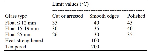
This guidance (CEN, 2004), since it is relatively crude and somewhat vague, provides limited information about the underlying processes and the real cause of glass breakage and thus is of limited use in complex situations, such as the composite members investigated in the current study. However, the studies mentioned above together with other studies on single glass panels exposed to radiant heating, (Wang et al., 2014; Debuyser et al., 2017; Wang, 2019), clearly show that cracks are initiated at the edges of panels from tensile stresses caused by large in-plane thermal gradients.
Several fire-resistance tests have been performed on glass walls, facades, windows, floors and overhead panels. A summary of these are given in the review by Bedon (2017). For beams in particular, four-point bending tests were performed on very small Laminated Glass (LG) beams (40×400 mm) with different configurations of annealed, chemically toughened glasses (with and without transparent intumescent coating) exposed to a burner with a flame temperature of 650°C on one side (Veer et al., 2001). Annealed LG beams broke very early under loading, but chemically toughened glass sometimes endured over 30 min with a temperature of >250°C on the non-exposed side. Interlayer failure, leading to loss adhesion between panels, was the predominant cause of collapse. The results also showed very good performance of the intumescent coating. Similar tests were carried out by Bokel et al. (2003) on LG beams with fire resistant glass with epoxy interlayers. The interlayer failed early in the test resulting in very poor performance at elevated temperatures.
Thermal exposure from the standard timetemperature curve as defined for fire resistance testing (according to ISO 834 or EN 1363) to LG beams with dimensions of 1 m and a fire exposed length of 0.8 m was conducted by Louter and Nussbaumer (2016). These, still rather short beams, had a height of 100 mm and consisted of three glass panes, 10 mm in thickness. Three tests were conducted on annealed, heat strengthened and fully tempered glass. The upper parts of the beams were covered from heat exposure. The results appeared very promising, all beams lasting >30 min without brittle failure. The PVB interlayer completely disappeared but the laterally supported panels showed a ductile response. It should however be noted that the loading (in total 115 kg in four-point bending) was very low compared to the beam dimensions.
Up until now, no tests have, to the best of the authors’ knowledge, been performed on timber-glass composite beams which is the topic of the present paper. Except the obvious difference in addition of the of timber flanges, which contributes to load bearing capacity but also induced large thermal gradients at the position of highest tensile stress, the main difference compared to previous tests on pure glass beams is the size (span of ~3 m). In addition, the tests were studied by numerical simulations to understand the mechanisms of failure of the glass web.
Experimental
Three identical beams were constructed, each 3920 mm in length. Each beam had a web consisting of three 10 mm thick and 190 mm high annealed glass panels laminated with PVB interlayer, 1.52 mm thick. The glass web was bonded to timber flanges with a height/width of 45/95 mm. The flanges had a cut groove of height/width = 22/37 mm and that filled with Epoxy Adhesive 7260 FC B/A from 3M (2019). The cross section can be seen in Fig. 3 (upper). The densities and the elastic modulus of the full batch of timber studs were measured and the mean values determined to be 460(45) kg/m3 and 12(2.1) GPa respectively, where the standard deviations are given within the parentheses.
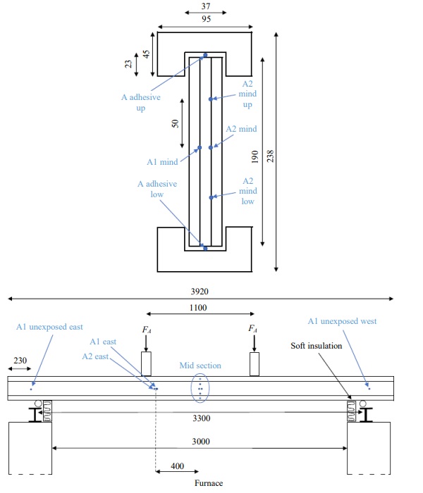
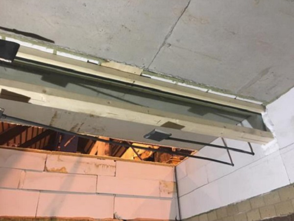
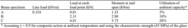
Table 2: Applied external load on the beams
The beams were instrumented with 0.5 mm thick type K thermocouples (TC) in both of the interlayers and in the adhesive between web and flange at mid span according to Fig. 3 (upper). In addition, TCs were positioned 400 mm along the length in the interlayers at midheight of the web. Close to the ends of the beams, without any fire exposure, the temperatures on the outer panels were recorded, Fig. 3 (lower). All the TC wires were drawn straight up (or down, depending on what was closest) to the web/flange interface and ran in the adhesive along the length of the beam.
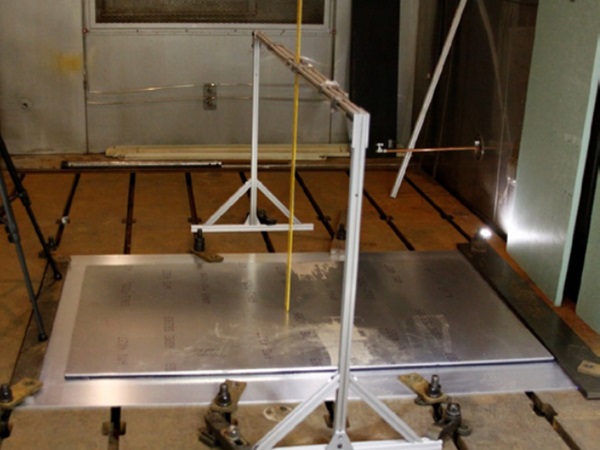
The beams were placed on a horizontal fire resistance furnace at RISE facility in Borås, Sweden. The opening of the furnace was 5 by 3 m and the beams were placed on roller supports across the short end with a total span of 3300 mm. All three beams were tested simultaneously placed 1400 mm apart. Each beam was unexposed for the most 460 mm of each end of the beam length. They were loaded with both a small line load, consisting of lightweight concrete blocks, of 0.154 kN/m and 4-point loading using two load points, each 550 mm from the midspan according to Table 2. The deflection at each load point was monitored throughout the test. Over the beams the furnace was covered with concrete blocks.
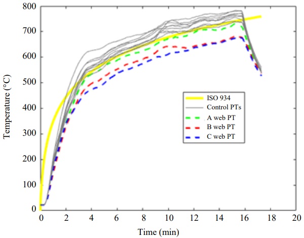
The temperature in the furnace was controlled by twelve Plate Thermometers (PT) according to the European fire resistance tests for load-bearing elements – beams, EN 1365-3. Each beam had three PT facing down and placed 100 mm below the lower flange at each load point and at mid span. In addition, each beam had one PT vertically oriented, facing away from the beam, 100 mm from the mid of the web, Fig. 4.
The furnace was run such that the average of all PTs followed the standard fire curve according to EN 1363 and ISO 834, T = 345∙log(8t +1)+20, where T is temperature in Celsius and t is time in minutes. The tests continued beyond complete failure of all beams and stopped after 16 min.
FEM Model
The fire tests of TGC beams were investigated using FE simulations and aimed at defining potential mechanisms behind the glass failure. In particular, focus was aimed at the temperature gradients and stress in glass caused by combined mechanical and thermal loading, presumably leading to cracking of glass panes.
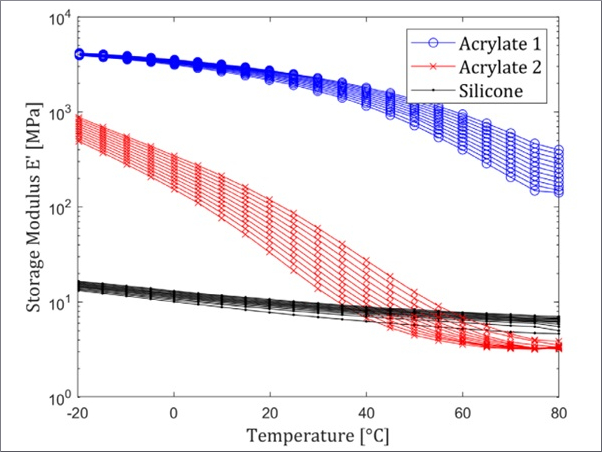
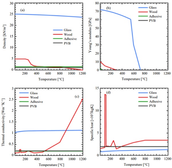
The input material properties of glass and timber were generally temperature dependent, as seen in Fig. 5. The values were taken from Östman et al. (2010) for timber (in which the properties were calibrated to match the thermal exposure according to ISO 834) and Shen et al. (2003) for glass. For the adhesive between the flange and the web as well as the PVB interlayer, material properties were kept constant except for Young’s modulus. For the adhesive, the value of Young’s modulus decreases rapidly from its value of 1800 MPa at 22°C to 1 MPa at 100°C. In case of the interlayer there are different values published for the Young’s modulus, including Bennison et al. (2008). Here the values from the Mepla Software (Mepla, 2019) were used, being 3 MPa at 22°C and dropping drastically at 40°C to 1 MPa. In addition, surface emissivities were set to 0.97 and 0.80 for glass and timber, respectively. The surface emissivity of glass should ideally comprise also transmission and possibly temperature dependence of the reflectivity but that is the scope of future work.
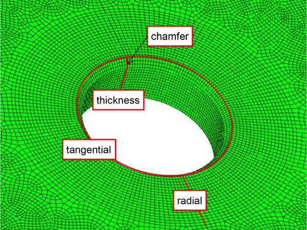
A 3D numerical model of the TGC beam was created using the commercial software ABAQUS/Standard (Dassault Systems, 2018), Fig. 6. Solid brick elements were used to reproduce the nominal geometry of the test setup involving of all components of the TGC beam: Laminated glass web (consisting of glass panels and interlayer) bonded to timber flanges with epoxy adhesive. To increase the computational efficiency of simulations, only a quarter of the beam with appropriate symmetry restraints was modelled.
To combine the thermal strains and those resulting from mechanical loading a two-stage approach was applied as reported by Bedon et al. (2018).
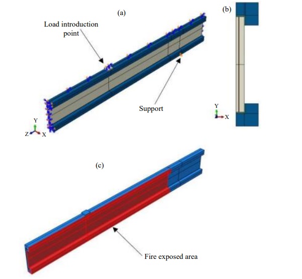
In the first stage, a heat transfer model was employed to determine the temperature history in all components of the TGC beam subjected to fire. All components were modelled using 8-node linear heat transfer bricks (DC3D8 elements from ABAQUS elements library (Dassault Systems, 2018). The heat transfer boundary conditions (i.e., radiation and convection) were defined as incident radiation from a black-body with the temperature according to ISO 834, qinc = σ(TISO834)⁴ where σ is Stefan–Boltzmann constant and a convective heat transfer between the surface and the furnace gas temperature (also defined as TISO834) with a convective heat transfer coefficient of 25 W/m²K to all exposed surfaces of the beam, Fig. 6c. The upper part of the upper flange was insulated and thus no fire load was applied. The elements were meshed with the assumptions: A global seed of 10 mm and minimum 3 elements through the thickness. From this model the thermal stresses were read and further investigated.
In the second stage of the study, a static analysis has been performed in which all components were modelled using 8-node linear bricks (C3D8R elements from ABAQUS elements library). The mesh was kept the same as in the heat transfer model. The beam was simply supported and restrained against the lateral torsional bucking (by restraining the top flange from out-of-plane deformation) to represent the boundary conditions in the physical test. In the model, temperatures obtained from the heat transfer model were applied as a pre-defined temperature field as well as the mechanical loads (static loads applied in fire test according to Table 2). The mechanical loading consisted of two nature: Uniformly distributed pressure (representing the line load shown in Table 2) and a point load applied to a steel plate 10 mm in thickness and dimensions of 95x95 mm placed on the top surface of the top flange at the load introduction points.
This approach yielded the combined mechanical and thermal stresses. Finally, for comparison the same procedure and boundary conditions was applied to a pure glass beam (in order to investigate the of a model without the timber flanges).
Results
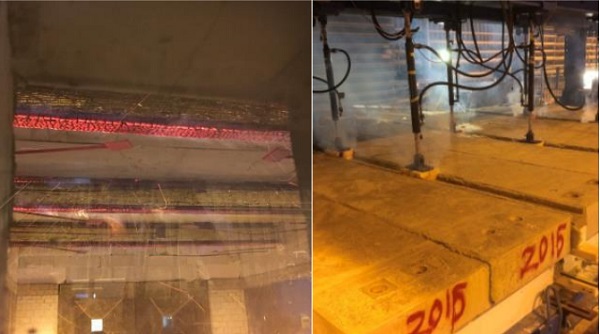
Initial cracking of some lamellas occurred very early in the test, at times 3.2, 3.4 and 3.9 min for beams C, A and B, respectively. Thus, the order did not monotonically follow the applied load. Due to the limited access to the furnace and inspection widows it was not 100% clear in which order the three lamellas broke, however, the remaining panels lasted for a significantly longer period. The cracking was considerable after just a few minutes as seen in Fig. 11. At the centre height of the web the cracks run mostly along the length of the beam but closer to the lower flange the cracks are vertically oriented.
During the test the flange started to char, forming a low conductivity char layer slowing down the heat transfer to the inner part of the timber as always is observed during fire testing of timber beams, Fig. 7. The thinner cross-section reduces the capacity of the flanges which, in combination with the reduced capacity from the broken web lamellas and the slightly reduced material stiffness of the yet unbroken lamellas caused the beams to deflect into the furnace. Complete failure appeared for the beams in reversed order of the applied load and occurred at approximately 8, 10 and 14 min for beams C, B and A, respectively, just as expected.
The temperature evolution of the PTs followed the ISO 834 fire curve within acceptable limits of the standard. The vertically oriented PTs, representative of the glass web exposure, are on average 70°C colder than the PTs facing down from below the lower flange, Fig. 8. The web PT of beam A was hotter than the web PTs of beams B and C. The PTs facing down had no systematic variation between the different beams. These differences are a common feature in fire resistance testing where thermal exposure never is 100% uniform (Lange et al., 2020).
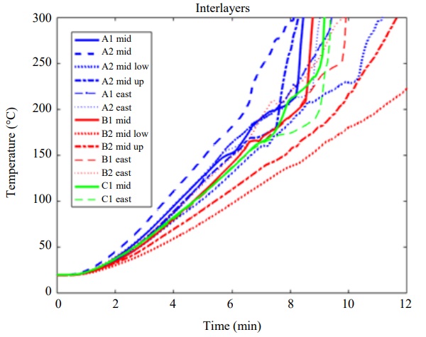
Five of the 18 interlayer TC unfortunately failed during the production of the webs for beams B and C, however, all in beam A were undamaged. Beam A interlayers exhibit between 40 and 15% larger temperature increase compared to the beam B and C (Fig. 9) which is in accordance with the higher plate thermometer temperatures at the web of beam A, Fig. 8. It also explains why beam A exhibited a faster initial lamella breakage compared to the beam B despite being subjected to a lower load.
The temperature distributions within beam A shows that the 2nd interlayer (closer to the furnace center) is hotter? than the one facing the furnace wall and the difference is about 15°C at the time of first lamella breakage. The temperature appears homogeneous over the length of the beam (at least sufficiently far away from each end of the beams which were not exposed to heating), this also confirmed by the results from beam B and C. There is a temperature gradient in the vertical direction of the web. The mid position is the warmest, the position 25% of the web height above the mid is just a few degrees colder for beam A but colder for the lower position. The difference is about 25°C at the time of the first lamella breakage but grows to 50°C after six minutes. The same behaviour was found for the beam B with similar differences between high and low position, Fig. 9.
The adhesives are heated to a significantly lesser extent than the interlayer. The adhesives in the lower and upper flange show just about the same temperature and three beams show almost identical behaviour, Fig. 10. During the test prior to collapse, the adhesive temperature, effectively protected by the timber char, stays below 100°C. At a later stage, at 15 min, the temperature increases rapidly and then follows the same temperature evolution as before. This is completely in line with the thermal behaviour of the epoxy adhesive which exhibits partial evaporation of 60-70% of its mass around 200°C in a clear exothermal process as shown by TGA and DSC (Kozłowski et al., 2018a).
The initial cracking can be noticed as small, sudden deflections at the load points, Fig. 11. After the initial cracking of the first panels (at 3.2, 3.4 and 3.9 min for beams C, A and B, respectively) continuous deflection changes in combination with small sudden jumps as more cracks in the panels are noticed. It is not clear from the data or from the visual observations during the test which of the three panels that broke for each beam.
FEM Modelling
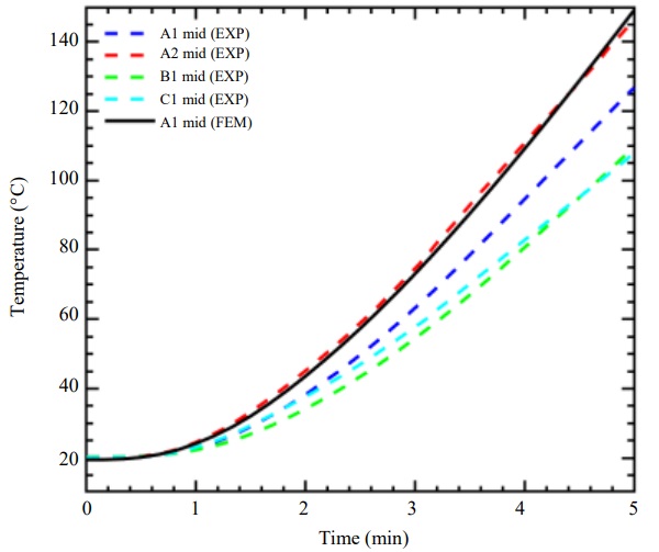
Figure 12 shows a comparison of numerical and experimental results at the mid-point (Mid) of the glass web. During the experiment the temperatures were measured by TCs mounted within the interlayer of the glass web at the mid height of the glass web, results shown in Fig. 9. Differences are found for the beams installed at different locations inside the furnace. The temperatures obtained from numerical simulations fit rather well the experimental results. The best agreement was found for the beam A and the TC located on the side that was closer to the centre of the furnace. In case of the beams B and C, the numerical model overestimates the experiments by approximately 30°C at 5 min of the simulation. This phenomenon may be related to the fact that the temperature was uneven in the furnace during the test and that the convective heat transfer coefficient also varies along the length and height of the beam. Neither of these were considered in the numerical model.
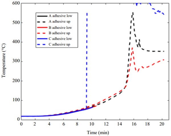
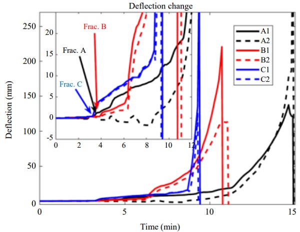
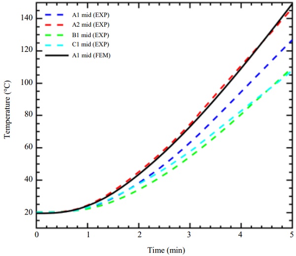
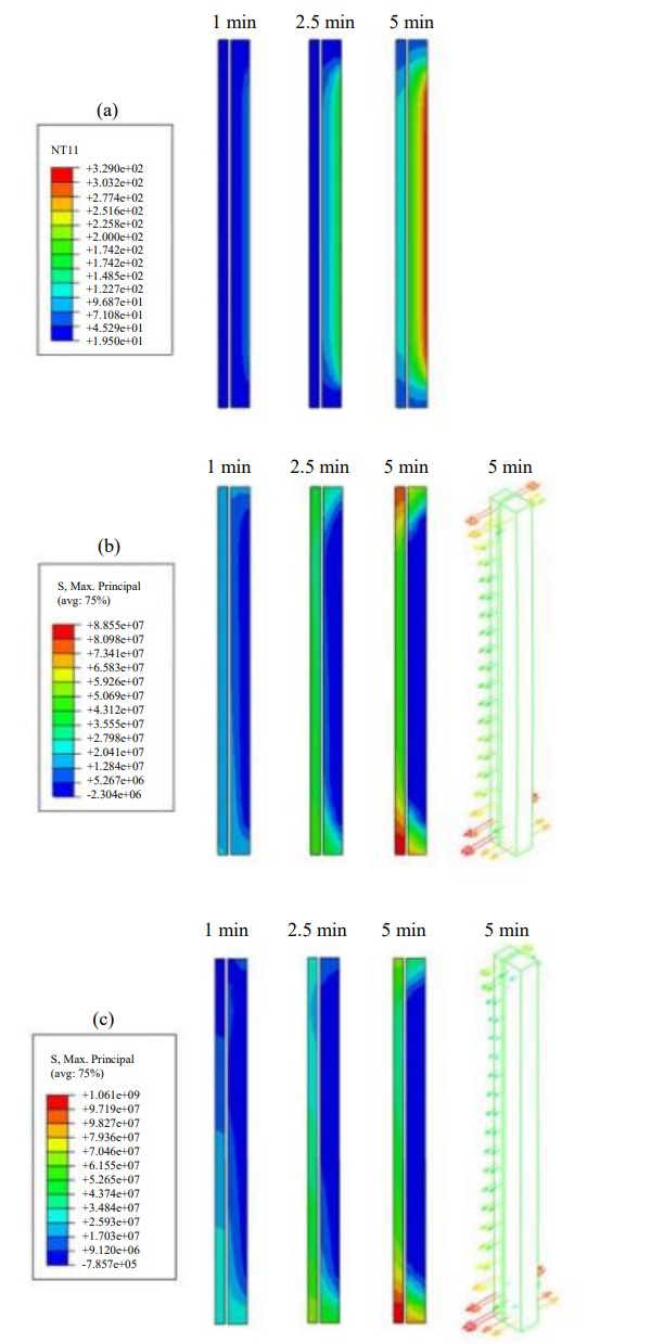
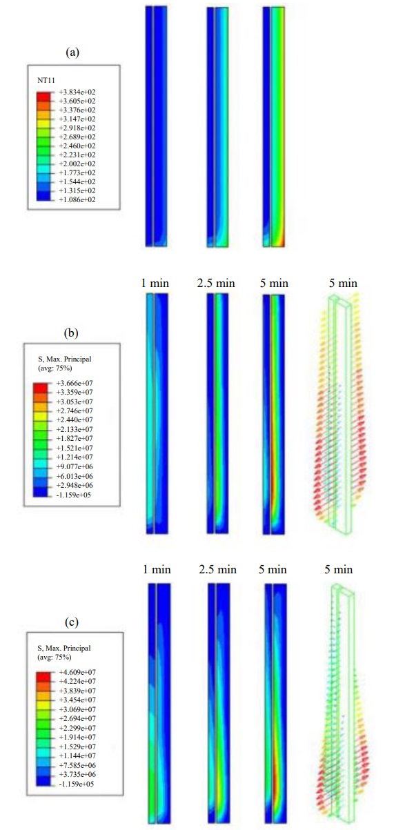
Figure 13 presents results of the numerical simulations of the beam exposed only to temperature loading as well as combined temperature and mechanical loading at times 1, 2.5 and 5 min of exposure. The results of temperature and principal stresses are shown for the glass elements at the mid cross-section of the beam. Although the temperature difference between covered and uncovered parts of the outer pane is significant (>280°C after 5 min) the highest thermal stresses are at the lower and upper part of the inner lamella, which reaches almost 90 MPa after 5 min of thermal exposure. The reason for this is most likely the shading and insulating effect of the lower flange, keeping the lower part of the inner lamella colder than the expanding outer lamellas.
As a result, the outer lamellas, in compression, are pulling on the inner lamella resulting in a high tensile stress which is also supported by the fact that the stresses are directed almost completely along the length of the beam. When the mechanical load is applied (Fig. 13c shows the case of beam A) the tensile stress in the lower part of the web increases whereas the compressive action close to the upper flange compensates the tensile stress resulting in a stress reduction of about 30%. The lower part of the web instead reaches a maximum tensile stress of just under 100 MPa at 5 min for the inner lamella whereas it is around 60-65 MPa at the lower part of the outer lamella. It should be noted that failure of the glass is not included in the model.
The evolution of the maximum stress anywhere in the beam, simulated without the mechanical loading and with the three load levels tested are shown in Fig. 14. It is clear that the (generally low) applied load levels make a rather small difference in the total stress which, again, seems to be dominated by the thermal gradients.
The temperature and stress distributions as shown in Fig. 13 are shown in Fig. 15 for the case of a pure glass beam, thus without the timber flanges. The maximum temperatures are a little higher but the thermal gradients significantly lower compared to the case with the beam with timber flanges. However, the largest influence of the flange presence can be seen in the thermal stresses which reach only half of the maximum value as in the case with timber flanges. More importantly, the position for the highest stresses are between the inner and outer lamella away from the lower edge instead of at the bottom part of the inner lamella. At the lower edge of the glass web the tensile stress is less than 10% of that obtained as the timber flange was considered.
Discussion Clearly, the glass web failed early in the tests primarily due to the stresses caused by large thermal gradients and not due to the applied mechanical load on the beams. However, the failure was not completely brittle but after the first lamella failure the displacement of the beam progressively increased until 8-15 min (depending on the applied load). The failure criteria of EN 13501-2 length and height of L and d is a maximum deflection of D = L² /(400d) together with a maximum deflection rate of dD/dt = L² /9000d. The criteria for the rate of deflection is reached early on, depending on the time interval used for the derivative, but the maximum deflection is reached after 9, 10 and 14 for beam C, B and A, respectively.
Which lamella that failed first for each beam was unfortunately not possible to determine during the tests but the FE simulations clearly suggest that it is the inner lamella that fails at the early stage of 3-4 min for all three beams, Figs. 14 and 15. This seems to be an effect of the added timber flange and corresponding shading effect since simulations without the flange showed less thermal stress and the position for the maximum stress was shifted closer to the mid height of the web. Thus, the shading of the flange keeps the lower (and upper) part of the inner lamella colder and the tensile strain caused by the heating of the outer lamella is therefore greater compared to a case without the flanges. Without this shading, the stress is lower and occurs away from the edge of the panel, which is the most critical position for initiation of cracks. Ironically, the additional capacity gained by the timber flanges cannot compensate the thermal stress behaviour and the TGC beams show less fire resistance than the glass web itself. This claim is based on FE simulations, however, this is also supported by previous tests on pure glass beams which does not show the rapid failure of panels and crack formation as the beams in this test (Louter and Nussbaumer, 2016).
The results show that the benefits of adding the timber flanges is, for this specific setup, balanced by the fact that thermal stresses develop much faster due the shading effect from the flanges. However, as there is much to gain from this design in ambient conditions (Kozłowski et al, 2015) some modifications to the design could be done in order to counteract the low fire resistance shown by the beams.
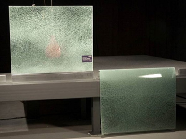
The most obvious but perhaps least resource efficient modification is to design the beam such that the timber flanges carry all the capacity needed and the glass just contributes to the aesthetics of the structure. This idea was applied in the roof structure of a conference room in the Palafitte Hotel in Switzerland (Kreher and Natterer, 2004), Fig. 2. Possibly more efficient is the use of different coatings or transparent intumescent films on the glass web to reduce the temperature gradients in glass. These types of measures have shown very good performance in the past such as shown by Veer et al (2001). A third option is to use heat-strengthened or fully tempered glass in the web or combination of different glass types. Several experiments have shown that the heat-strengthened or fully tempered glass show much better performance when exposed to fire.
The reason it is not used in applications such as this, is the characteristic brittle failure if it breaks due mechanical shock in ambient temperature. If, for example, an object is thrown at the web the annealed glass cracks and stays in position due to the interlayer connection the adjacent panel and the adhesives to the beam. A web consisting of laminated fully tempered glass would on the other hand exhibit a lower postbreakage stiffness compared to that of a laminated annealed glass web, with implications to occupants and structural integrity. Given the results from Fig. 13 one suggestion is to replace only the inner panel to more fire resistant glass since it appears that it is this panel that breaks first. Also chemically toughened glass could be an option which is yet to be explored.
Another option is to reduce the shading by not cutting a groove in the flange where the whole web thickness fits. Instead, the inner pane in the web could be of less height than the outer ones. A ridge in the timber flange could then be fitted between the outer panels, much like the reinforcement steel applied by Louter et al. (2012). The composite action from the timber-glass assembly could then be utilised without the premature failure of the web due to flange shading.
These are all subject of the future research and it is propose to launch simulations of different solutions to web/flange interaction to later test a new solution in a furnace which, in addition to the benefits in ambient conditions, also exhibits a better resistance to fire.
Conclusion
The combination of timber and glass in different structural elements are becoming more and more popular. Apart from the aesthetical and architectural reasons the combination of timber and glass in e.g. composite beams (TGC beams) have shown many significant structural advantages.
The performance case of fire is however a concern for TGC beams. This study describes an analysis of the fire resistant performance of TGC beams and shows that there are inherent problems with shading of a glass web by timber flanges for the performance in case of fire. However, there are many possible ways to overcome these issues by different modifications to materials or design.
Acknowledgement
Fredrik Dahlberg at 3M is acknowledged for helping with adhesive application and technicians at RISE (Fredrik Kahl, Emil Hallberg, Martin Rylander and Martin Rabe) for help during manufacturing and testing.
Funding Information
The authors acknowledge the financial support from ÅForsk (Structural performance of load-bearing timber glass composites - testing and modelling of timber-glass composites under temperature loading, grant number 17- 507) as well as Forserum Safety Glass, generously providing the glass webs. This publication was also supported under the Rector's grant in the field of scientific research and development work (Silesian University of Technology, grant number "241/RN2/RR4/2019").
Author’s Contributions
Johan Sjöström: Experimental design, construction of beams, performing experiment, analysis, writing and reviewing.
Marcin Kozłowski and Daniel Honfi: Experimental design, construction of beams, performing experiment, performing simulations, analysis, writing and reviewing paper.
David Lange: Experimental design, analysis, writing and reviewing paper.
Joakim Albrektsson: Experimental design, construction of beams, performing experiment, reviewing paper.
Peter Lenk: Experimental design, analysis and reviewing paper.
Jerry Eriksson: Experimental design and reviewing paper.
References
3M, 2019. 3M scotch-weld epoxy adhesive 7260 FC B/A. Technical Data Sheet.
Bedon, C., 2017. Structural glass systems under fire: Overview of design issues, experimental research and developments. Adv. Civil Eng., 2017: 2120570-2120570. DOI: 10.1155/2017/2120570
Bedon, C., X. Zhang, F. Santos, D. Honfi and M. Kozlowski et al., 2018. Performance of structural glass facades under extreme loads-design methods, existing research, current issues and trends. Constr. Build. Mater., 163: 921-937. DOI: 10.1016/j.conbuildmat.2017.12.153
Bedon, C. and C. Louter, 2018. Thermo-mechanical numerical modelling of structural glass under fire - preliminary considerations and comparisons. Proceedings of the International Conference on Architectural and Structural Applications of Glass, May 11-13, Delft University, Belgium, pp: 513-524. DOI: 10.7480/cgc.6.2173
Bennison. S.J., M.H.X Quin and P.S. Davies, 2008. High performance lamiated glass for structural efficient glazing. Proceedings of the Innovative Light-Weight Structures and Sustainable Facades Conference, (SFC’ 08), Hong Kong.
Ber, B., M. Premrov, A. Štrukelj and M. Kuhta, 2014. Experimental investigations of timber-glass composite wall panels. Constr. Build. Mater., 66: 235-246. DOI: 10.1016/j.conbuildmat.2014.05.044
Bokel, R.M.J., F. Veer and L. Tuisinga, 2003. Fire resistance of glass. Proceedings of the Glass Processing Days, Jun. 15-18, Tampere.
Debuyser, M., J. Sjöström, D. Lange, D. Honfi and D. Sonck et al., 2017. Behaviour of monolithic and laminated glass exposed to radiant heating. Constr. Build. Mater., 130: 212-229. DOI: 10.1016/j.conbuildmat.2016.09.139
CEN, 2004. prEN thstr:2004. Glass in buildings-thermal stress capitulation method. CEN, Brussels, Belgium.
Dorn, M., M. Kozłowski, E. Serrano and B. Enquist, 2014. Development of large-scale load-bearing timber-glass structural elements. Proceedings of the World Conference on Timber Engineering, Mar. 10-14, Quebec City.
Furtak, K. and K. Rodacki. 2018. Experimental investigations of load-bearing capacity of composite timber-glass I-beams. Arch. Civil Mechanical Eng., 18: 956-964. DOI: 10.1016/j.acme.2018.02.002
Haldimann, M., A. Luible and M. Overend, 2008. Structural use of Glass. 1st Edn., IABSE, Zürich, Switzerland, ISBN-10: 3857481196, pp: 215.
Honfi, D., D. Lange, M. Kozłowski, J. Sjöström and P. Lenk, 2018. Behavior of load‐bearing glass at elevated temperature. ce/papers, 2: 533-540. DOI: 10.1002/cepa.952
Keski-Rahkonen, O., 1998. Breaking of window glass close to fire. Fire Mater., 12: 61-69. DOI: 10.1002/fam.810120204
Karlsson, S., 2017. Spontaneous fracture in thermally strengthened glass-a review and outlook. CeramicsSilikáty, 61: 188-201. DOI: 10.13168/cs.2017.0016
Kozłowski, M., 2014. Experimental and numerical analysis of hybrid timber-glass beams. PhD Thesis, Silesian University of Technology, Gliwice, Poland.
Kozłowski, M., E. Serrano and B. Enquist, 2014. Experimental investigation on timber-glass composite I-beams. Proceedings of the Challenging Glass 4 and COST Action TU0905 Final Conference, Feb. 6-7, CRC Press, Lausanne.
Kozłowski, M., M. Dorn and E. Serrano, 2015. Experimental testing of load-bearing timber-glass composite shear walls and beams. Wood Mater. Sci. Eng., 10: 276-286. DOI: 10.1080/17480272.2015.1061595
Kozłowski, M., P. Lenk, M. Dorn, D. Honfi and J. Sjöström, 2018a. Structural considerations on timberglass composites at fire scenarios. Proceedings of the Challenging Glass Conference Proceedings, Jun. 18-19, Ghent. DOI: 10.7480/cgc.6.2150
Kozłowski, M., C. Bedon and D. Honfi, 2018b. Numerical analysis and 1D/2D sensitivity study for monolithic and laminated structural glass elements under thermal exposure. Materials, 11: E1447-E1447. DOI: 10.3390/ma11081447
Kreher, K. and K.J. Natterer, 2004. Timber-glasscomposite girders for a hotel in Switzerland. Structural Eng. Int., 14: 149-151. DOI: 10.2749/101686604777963964
Lange, D., J. Sjöström, J. Schmid, D. Brandon and J. Hidalgo, 2020. A comparison of the conditions in a fire resistance furnace when testing combustible and non-combustible construction. To Appear in Fire Technology.
Lenk P., C. Noteboom and M. Arkinstall, 2018. Hybrid glass structures-design philosophy and selected checking procedures. Proceedings of the Challenging Glass Conference Proceedings, May 11-13, Delft University, Belgium. DOI: 10.7480/cgc.6.2199
Louter, C., J. Belis, F. Veer and J.P. Lebet, 2012. Structural response of SG-laminated reinforced glass beams; experimental investigations on the effects of glass type, reinforcement percentage and beam size. Eng. Struct., 36: 292-301. DOI: 10.1016/j.engstruct.2011.12.016
Louter, C. and A. Nussbaumer, 2016. Fire testing of structural glass beams; initial experimental results. Proceedings of GlassCon Global Conference, Jul. 6-9, Boston.
Malou, Z., H. Hamidouche, N. Bouaouadja, J. Chevalier and G. Fantozzi, 2013. Thermal shock resistance of a soda lime glass. Ceramics-Silikáty, 57: 39-44.
Martens, K., R. Caspeele and J. Belis, 2015. Development of composite glass beams-a review. Eng. Struct., 101: 1-15. DOI: 10.1016/j.engstruct.2015.07.006
Mepla, 2019. MEPLA-software for structural glass design. Mepla. h
Mognato, E. and A. Barbieri, 2013. The breakage of glass-thermal shock and nickel sulfide inclusions. Proceedings of the COST Action TU0905 Mid-term Conference on Structural Glass, Apr. 5-5, CRC Press, Boca Raton. DOI: 10.1201/b14563-23
Nicklisch, F., S. Hernandez Maetschl, M. Schlehlein and B. Weller, 2015. Development of load-bearing timber-glass composite shear wall elements. Proceedings of the Glass Performance Days, Jun. 24-26, Tampere.
Östman, B., 2010. Fire safety in timber buildingstechnical guidelines for Europe. SP Report 2010:19, SP Technical Research Institute of Sweden, Stockholm.
Pagni, P.J. and A.A. Joshi, 1991. Glass breaking in fires. Fire Safety Sci., 3: 791-802. DOI: 10.3801/IAFSS.FSS.3-791
Scleicher, A., 2016. Fire protection concepts for timberglass composite facades. MATEC Web Conf., 46: 05003-05003. DOI: 10.1051/matecconf/20164605003
Shen, J., D.J. Green, R.E. Tressler and D.L. Shelle-Man, 2003. Stress relaxation of a soda lime silicate glass below the glass transition temperature. J. NonCrystalline Solids, 324: 277-288. DOI: 10.1016/S0022-3093(03)00260-6
Dassault Systems, 2018. Simula ABAQUS v. 6.14; Computer Software and Online Documentation.
Veer, F., M. van der Voorden, H. Rijgersberg and J. Zuidema, 2001. Using transparent intumescent coatings to increase the fire resistance of glass and glass laminates. Proceedings of the Glass Processing Days, Jun. 18-21, Tampere, pp: 392-396.
Vandebroek, M., 2015. Thermal fracture of glass. PhD Thesis, TU Ghent, Ghent, Belgium.
Wang, Q., H. Chen, Y. Wang and J. Sun, 2013. Thermal shock effect on the glass thermal stress response and crack propagation. Proc. Eng., 61: 717-724. DOI: 10.1016/j.proeng.2013.08.118
Wang, Y., Q. Wang, G. Shao, H. Chen and J. Sun et al., 2014. Experimental study on critical breaking stress of float glass under elevated temperature. Mater. Design, 60: 41-49. DOI: 10.1016/j.matdes.2014.03.038
Wang, Y., 2019. Experimental and Numerical Study of Glass Façades Breakage Behavior under Fire Conditions. 1st Edn., Springer, Singapore, ISBN-13: 9789811364839, pp: 139.