This paper was first presented at GPD 2023.
Link to the full GPD 2023 conference book: https://www.gpd.fi/GPD2023_proceedings_book/

Authors: J. Vetterli, Ph. Willareth, E. Bouleau
Abstract
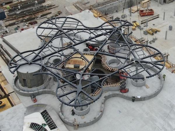
The Greenhouse is the centre of the new public park "Operaparken" in Copenhagen's inner harbour, which was developed in a competition in 2019 until finalisation in 2023 by Cobe Architects.
The "green lung" of the pavilion is formed by an atrium that extends over three stories, two of them are underground, surrounded by the parking areas. The atrium is separated by curved glazing and is heavily vegetated. On the ground floor park level, the pavilion with a diameter of about 45m, is characterised by the curved layout and a thin steel roof.
In the original design, the roof was supported on the all-glass façade, to reduce it’s deformation. In the course of ecological and economic optimisations, a design change took place, whereby the roof was developed as a self standing, pre-shaped construction with tension rods in the façade. The glazing is no longer load-bearing. Therefore the glass thickness could be reduced by a third, which increases transparency and saves resources.
The resulting new demands on the glass elements, especially in combination with the tension rods and a stress-free assembly, required unconventional solutions in the construction of the façade.
The report reflects the close cooperation between architecture, structure engineering and façade development and shows how resources can be saved with cross-disciplinary solution concepts.
1 Introduction
1.1 Context
The Operaparken Project is a public park that occur in the inner harbour of Copenhagen on the Dock Island.
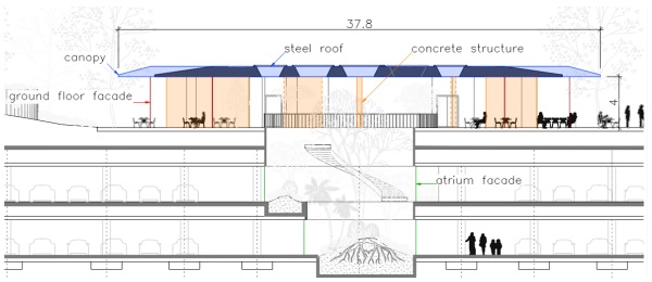
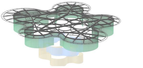
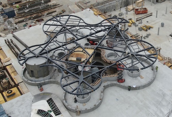
A filigree pavilion is being built in the center of this park. The vertical section (Figure 1) shows the atrium extending over two parking levels and the ground floor space enclosed by a perimeter non-insulated curved glass façade. Three concrete cores colored in orange contain lift facilities and bathrooms. The steel roof is following the façade and has an overhanging canopy that varies in depth. The structure and the complex geometry of the façades and roof structure can be seen in the Isometry (Figure 2). In this contribution the focus lies on the steel roof and the ground floor façade. These were the most challenging areas that required a high level of cooperation between the various planners.
1.2 Design Process
The project was only taken over and further processed by Dr. Luechinger Meyer at an advanced planning stage regarding steel construction and façade planning. At the beginning, the existing design material were reviewed and comprehended. The previous design has foreseen to support structure of the roof by a load-bearing glass façade.
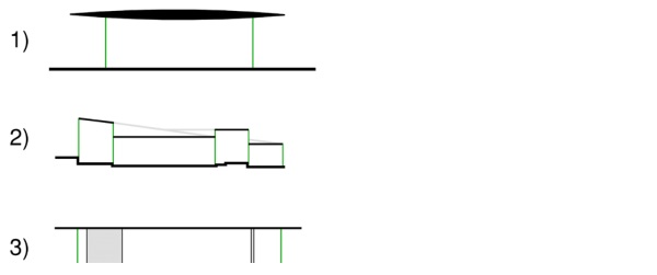
The project was compared with the design principle of similar buildings containing a load-bearing glass façade - whereby there is a significant difference (Figure 3). In the case of the Steve Jobs Theatre (1) and the Audemars Piguet Museum (2), the roof construction s supported exclusively by glass walls. The Operaparken Pavilion (3) has, in addition to the façade, cores and columns in concrete as support for the roof construction. The glass façade was used exclusively to reduce deformation and is no longer included in the Accidental load case, where, for example, the roof must be self-supporting in case of fire. Based on these findings, the supporting structure of the pavilion was discussed in interdisciplinary workshops. In close cooperation with the architects, structural engineers and façade planners, the supporting structure of the roof and façade was revised and rethought. The new load-bearing concept provides for a pre-stressed steel structure and thus a non-load-bearing façade. The impetus for this was above all the reduction of complexity and material, the interdependencies in the execution and the optimisation of resources and costs. Careful coordination of the various planners and contractors is essential for a successful project.
Design, deformations and tolerances play an essential role in this process. The early involvement of the steel constructor was also an important point for the feasible planning.
1.3 Geometry and Key Figures
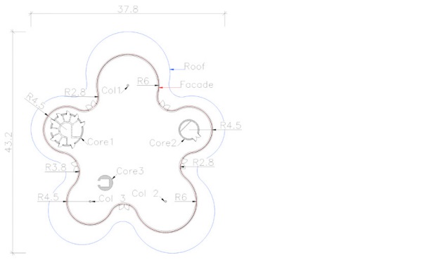
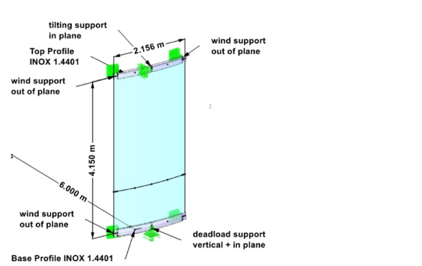
The pavilion measures 43 x 38m and has a roof area of around 1100 m2. The non-insulated glass façade consists of alternating concave and convex circular segments (Figure 4) enclosing the interior space of approx. 700m2 and is set back towards the roof edge from 2 to 4 meters. The glass radius varies from 2.8 to 6 m with glass dimensions of 2.2 x 4.2m. There are five entrance doors integrated in the façade.
2 Structural Engineering
2.1 Structural concept
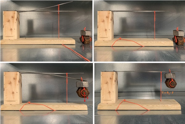
Instead of vertical supports on the façade, the new load-bearing concept for the roof construction provided for producing the steel construction pre-shaped upwards and setting it in the desired position in the plane of the façade using prestressing cables (Figure 5). In conclusion, the entire roof structure must act as one component, whereby the different support positions and spans meant different stiffnesses and thus different pre-shaping for every single beam.
The key to a successful implementation of the idea was to maintain the filigree of the structure right from the start and to get all the planners and the client on board and convinced of the idea. A variety of materials and positions for the tension lamellas were tested. In the end, a duplex stain-less steel with a dimension of 25 x 6 mm is positioned on the inside at the glass joints. It’s visible and tangibly by the visitor, the mirror finish reduces its visibility from a greater viewing distance (Figure 6).
2.2 Façade concept
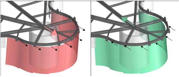
For the façade, the change in structural design means that no vertical loads are transferred through the glass. The focus was now on integrating the prestressing cables of the steel structure, preventing constraints in the glass and ensuring the absorption of displacements at the intersections. For example, the thermal expansion of the steel structure affects each pane of glass individually, which leads to different displacements of the glass edges (Figure 7).
To ensure that movements of the steel structure do not generate destructive forces in the glazing, it is imperative that the glass is mounted with hinged joint connections.
The glass must be able to move freely with the steel roof, as well as the tension lamellas.
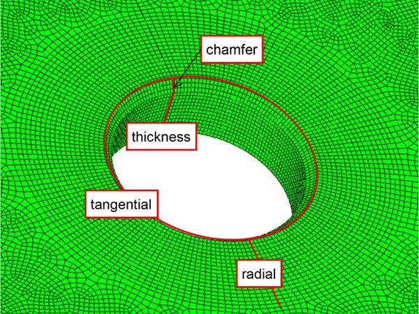
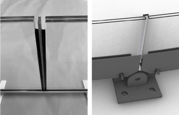
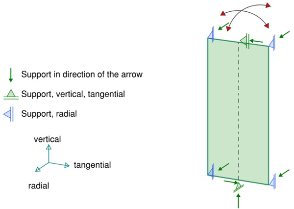
The glass elements are pin - supported in the centre to allow a rotation. These supports take vertical and tangential loads. Radial supports in all four corners of the glass prevent the pane from rotating and take wind loads. By decoupling the various support conditions and following a clear structural concept, the individual supports could be simplified (Figure 8).
3 Design engineering
3.1 Steel Roof design
The pre-deformation of the roof was determined using an FE model. The maximum pre-shape is 112mm. The aim was to have the same pre-stressing force acting in all tension lamellas despite the irregular structure. In the case of a superimposed load, this pre-stressing force is reduced, whereby the deformation at the edge beam above the façade is reduced to an absolute minimum. Settlements of the concrete structure also had to be taken into account, as well the subsequent backfilling of the soil for the park. The tensile values vary depending on the load and case, to a maximum of 90kN, vertical deformation at the façade could be reduced to 10mm. A non-linear anchoring of the upper Lamella point prevents buckling in the case it’s unloaded and the roof deflects.
3.2 Façade design
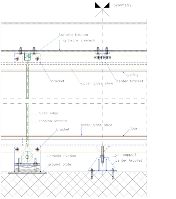
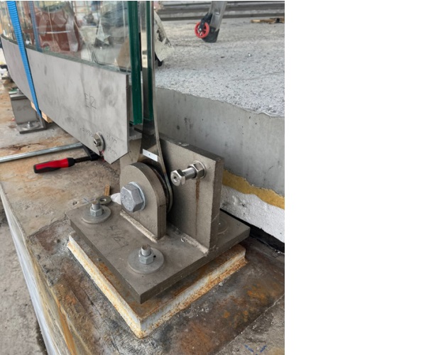
The curved glass panes are line-supported on 2 sides at the short edges in specially manufactured glass profiles in stainless steel. These profiles are also used to fasten the glass elements. Synergies were used for the brackets, so the bracket for the tension lamellas also serves to fix the glass elements. Due to the high loads and horizontal tolerances, these brackets were welded on site with cast in steel plates. The center bracket is used only by the façade and could be carried out much simpler. Tolerances can be absorbed individually at each support point. Detailed Façade drawings can be seen on figure 11, 12.
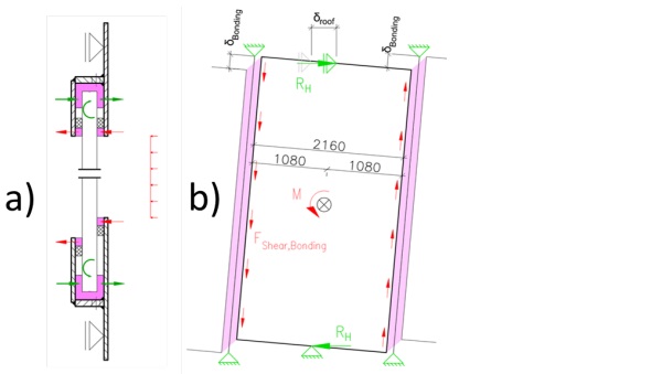
The glass dimensioning is carried out according to DIN18008. The glass structure consists of a laminated safety glass of 2 x 8mm heat-strengthened glass. To increase the rigidity of the glass, the structural interlayer from Trosifol, SentryGlas® Xtra, was used. Since the edge profile can rotate freely around its fixing points and is mounted slightly eccentrically, there is a small torsion in the profile. This eccentricity had to be accouted in all calculations and represents an additional load for the glass (Figure 9).
Due to the curvature of the glass panes, they have a much higher stiffness compared to flat glass. As a result, the glass build-up could be additionally reduced. Figure 10 shows the calculation model of the glass.
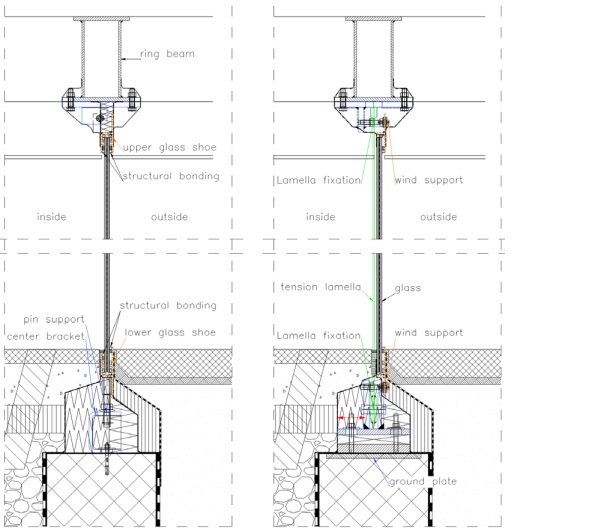
3.3 Structural sealing
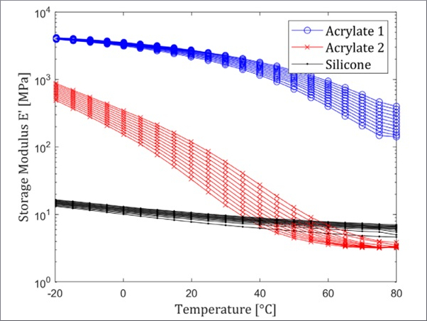
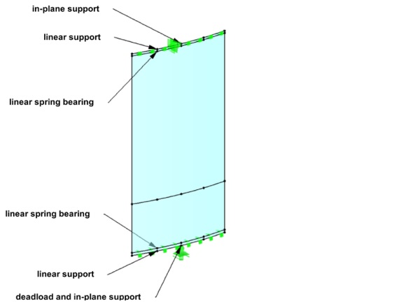
For the dimensioning and execution of the structural bondings we worked closely with Dow. The glasses were bonded to the glass profiles in stainless steel (Figure 13, a). For the calculation in global models, an elastic line bearing is added, which represents the pressure point at the profile, the continuous silicone bonding. The attribute of this spring bearing corresponds to the silicone joint with the mechanical values specified by the supplier. A high stiffness is afforded in this bonding, so the silicone Dowsil 993 was used. The vertical sealing of the glass-glass joints posed an additional challenge, as the joint is subject to shear stress due to the different tilting of the glasses (Figure 13, b). In order to keep the stresses in the adhesive joint low, it was essential to use a silicone with lower stiffness. For this reason, the silicone Dowsil 121 was better suited here.
4 Construction
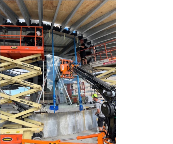
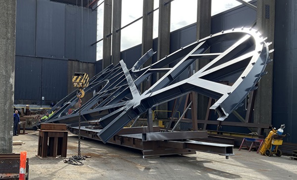
The roof was produced in three parts (Figure 15) and assembled on site (Figure 16). It was then pulled down and the tension lamellas were mounted (Figure 14). Due to tolerances in the large steel structure, this was an iterative process and the position of the roof and the prestress were adjusted. Once the position was correct, the brackets and slats could be mounted. The glass elements were then mounted, aligned with set screws, and glued to the steel profiles after assembly in order to accommodate additional tolerances (Figure 17, 18,).

5 Conclusion
Thanks to the interdisciplinary cooperation, the trust of the client regarding this unconventional design method and the finetuning with the architecture, the project could be greatly optimised by modifying the supporting structure. With approximately the same amount of steel, the glass structure could be reduced from 3x8mm to only 2x8mm LSG, saving a total of 9'150 kilogramms of glass, which corresponds to a GWP of about 16 tonns CO2 equivalent. In addition, the transparency of the glass façade was increased and glass replacement is massively simplified. Despite the time pressure and the extensive project change for all project partners, the change was managed with great motivation and commitment by all those involved, which paid off with the successful project.
6 Acknowledgement and project partner
Client: Operaparkfonden c/o A.P. Møller Fonden
Architecture: COBE, Kopenhagen
Structural Engineering: VITA ingeniører
Structural Engineering roof construction: Lüchinger+Meyer, Lausanne
Façade Engineering: Lüchinger+Meyer, Zürich / Lüchinger+Meyer+Hermansen, Copenhagen
Contractor Steelwork: HSM Industri A/S
Contractor façade mounting: Redtz Glas & Façade
Glass manufacturer: Haojing Group Holdings Glass Co